Jennie W, Masayuki N
Daniel set up some model changes last week in h1lsc to allow us to use the JAC-TRANS_A DCPD to lock the cavity. This is a workaround of what is intended to be the normal operation where the locking is done with the JAC-REFL_A PD on IOT1. Rolling this table up to the chamber would make it hard to install the optics on that side of the table so we need this workaround to see the beam transmitted through the cavity that we can use to align the beam from JAC into the IMC.
This PD is just a DC PD so we cannot use PDH to lock as we would for the REFL PD. Yesterday and today Masayuki and I worked on an offset lock, where we use the transmitted power offset to the side of the fringe after normalising the error signal by the maximum transmitted power on resonance.
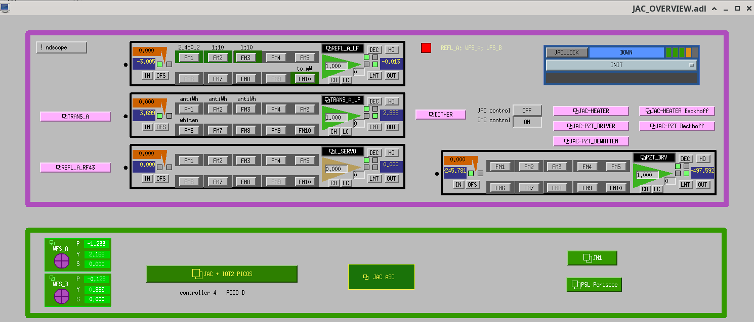
Use JAC Overview->DITHER. The demodulation is set up so the SIN gain is one and connects to I filter bank which also has a gain of 1. Q filter bank is terminated at the output.
First step is to use the ramp on JAC Overview -> JAC-PZT_Driver by pressing "ENABLE" in right-hand corner, the slider on the left side needs to be near -10V for this to work. Measure the max peak height of the TM00 mode - transmitted power off resonance.
The normalisation is done using the high pass filter bank block at the left of the screen, this opens up H1JAC-DITHER_PD_IN. The gain should be set to the normalisation constant, 1/(transmitted power on resonance - transmitted power off resonance).
The actual servo shaping is done using H1JAC-DITHER_SERVO, which is linked on the right of the 'DITHER' screen. Set the offset to -0.6 to shift the normalised error signal so the zero crossing is just below halfway up the fringe. Check the input and output of the filter bank after the servo are turned on, this is linked on the right of the 'DITHER' screen and is called 'PZT'.
Make sure the PZT ramping is turned off by pressin 'DISABLE on the JAC-PZT_Driver screen.
Turn on the UGF100 and LP10 filters in the 'H1JAC-DITHER_SERVO' filter bank. These have a gain of 3000 and a low pass filter which rolls off at 10Hz respectively. This latter one is to invert the PZT response.
The gain in this filter bank should be on, use the slider on the 'DITHER' screen to tune to a TM00 peak and then turn on the servo output. Once locked you can turn on the Int1Hz filter to add an integrator below 1Hz and the boost to give an extra 5x gain.
For a better lock we also implemented a proper DITHER SERVO.
The dither frequency is set to 2.5KHz and the demod phase is set at 0 degrees. The input signal no longer had normalisation in H1JAC-DITHER_PD_IN as the error signal will now be the beat between the PZT dither and the cavity transmitted power and so has a zero crossing at the centre of resonance.
There is a high pass filter in H1JAC-DITHER_PD_IN to avoid up-conversion of noise below 1 kHz. After the demodulation both 'I' and "Q' filter banks have a low pass filter at 1kHz to prevent 2.5kHz and harmonics from getting magnified by the loop.
Both I and Q phase now have a low pass filter at 1KHz to prevent harmonics of the dither frequency appearing in the error signal. The locking technique is the same after this point as the filters needed in the 'SERVO' block do not change as the actuator response has not changed.
Masayuki has set up both these locking processes in the JAC guardian but this is still WIP.


Here is the measurements we took so far.
Offset Locking erro point ASD when locked.


