It took much longer than expected but we set up the beam path for the RTP test in the OSB optics lab.
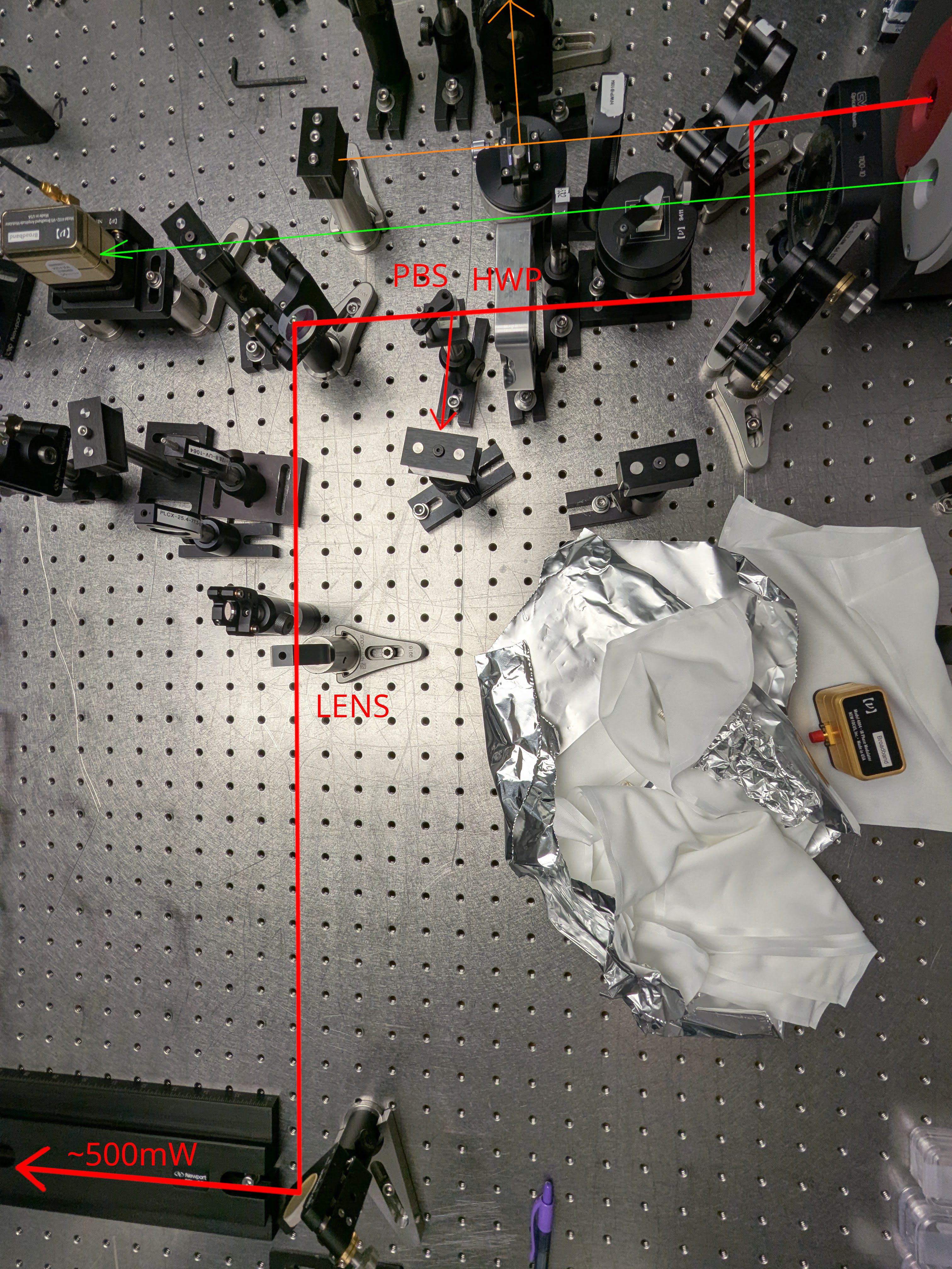
Since more power makes it easier to see the ghost beams, I removed the beam dump that used to receive most of the red power (~530mW) and directed the beam to the front of the table (red path in the attached). I stole the steering mirror that used to be used for the low power P-pol path (circled in red). The low power p-pol path is now simply blocked. No other change was made to low power S-pol path (orange) as well as green path (green), but the beams are blocked by beam dumps. If you want to use these, simply unblock.
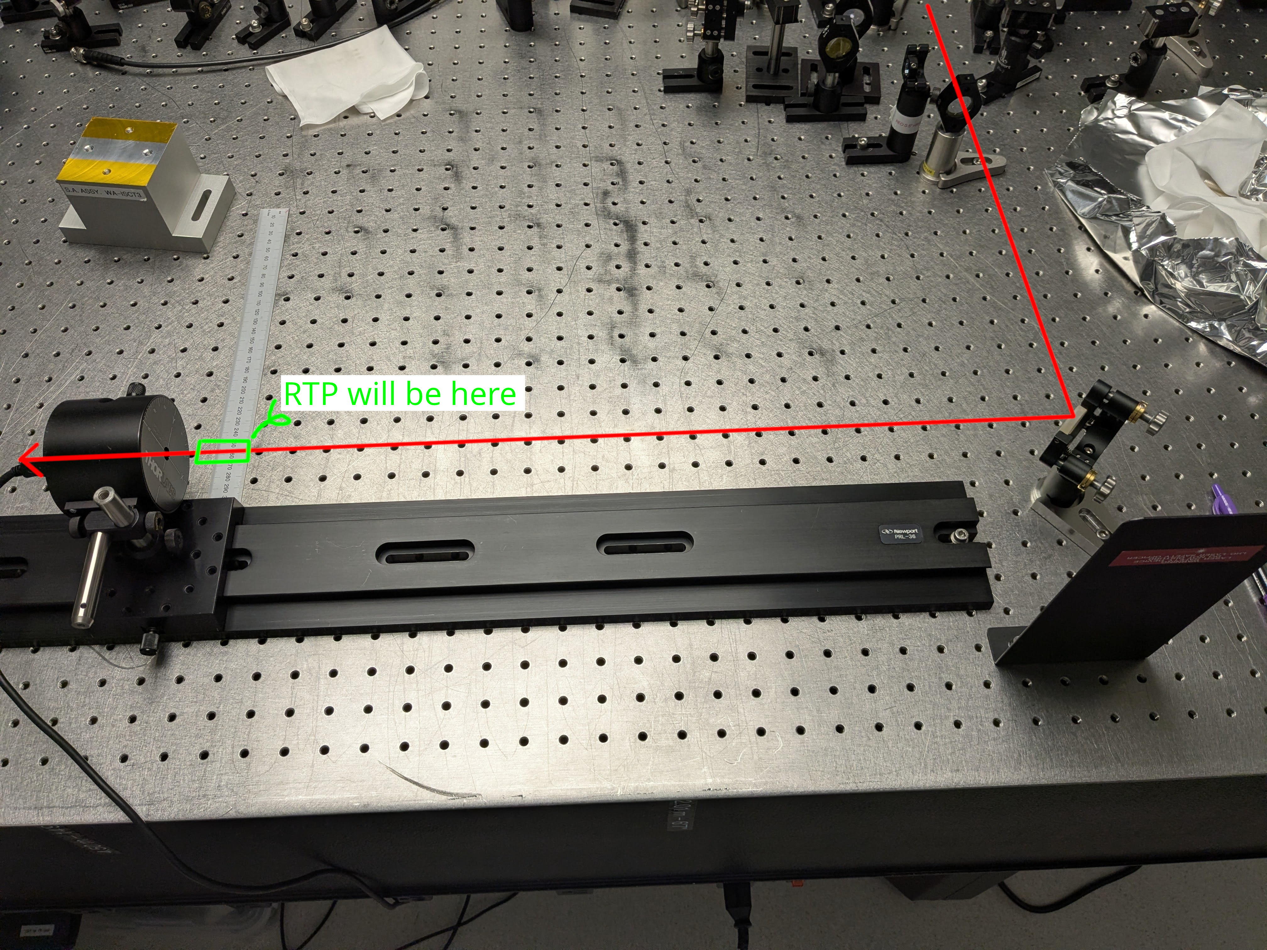
The beam radius will be 300~400 um or so at the location we plan to put the RTP (represented by a green rectangle in the second attachment). Elenna will post the plot of the beam size measurement.
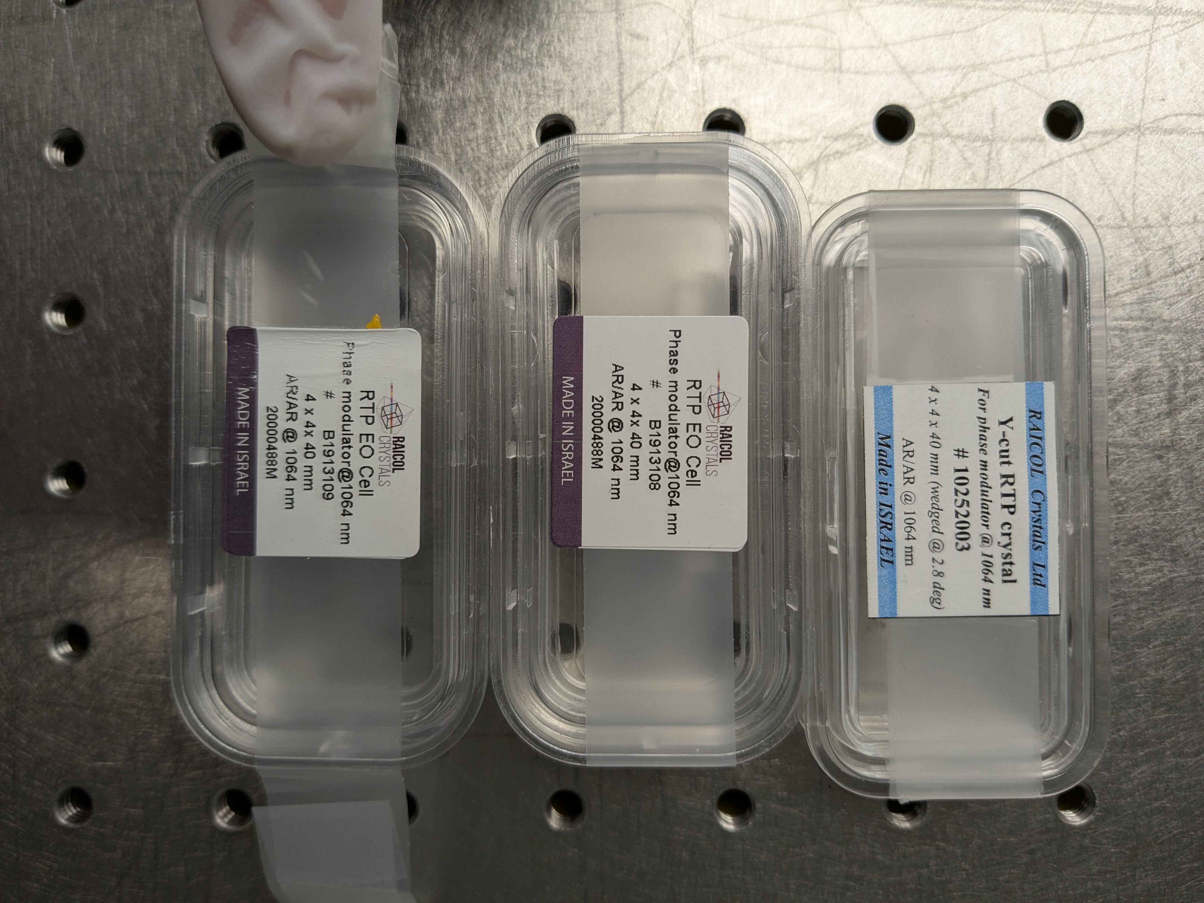
The third picture shows the containers for different RTP. Left is the one for the crystal in HAM1. The middle seems to be from the same batch. Right looks different, on the bottom of the container there's a label saying "I/O something something 2017" so this is likely the old one.
We didn't have time to actually test the crystals, wait for tomorrow's udpate.
I made a mistake when providing calculations to Keita about the beam profile- I incorrectly input our distances as mm instead of cm. However, I think it's ok overall.
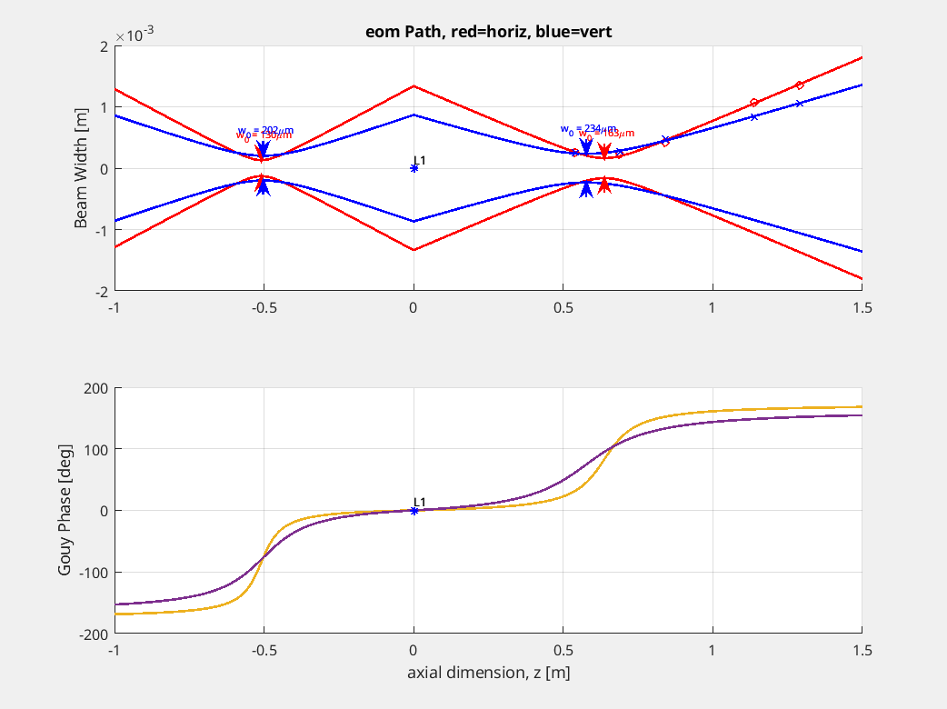
Keita and I put an available lens (f = 286.5 mm) into the beam path, and then used a thorlabs profiler on a rail to profile the resulting beam at five points. We measured distances from the lens to the profiler and accounted for the set back of our profiler from the edge of the mount, etc. This measurement allowed us to measure that the beam waist is roughly around the location of the laser, and is about 130 um in the x direction and 202 um in the y direction. Unfortunately, the beam quality isn't great, this is the best we could do. (Note, because of my mistake we chose not to use this particular lens, but it probably would have been fine for our measurements after all).
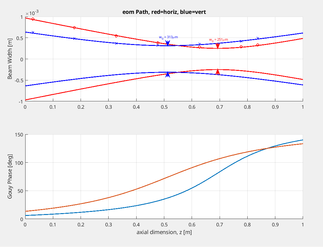
After some iteration, we determined that a f=401 mm lens was suitable, and we ended up placing it pretty close to the original lens location. We ran another profile measurement and found that we could achieve a beamsize of about 313 um in the y direction and 251 um in the x direction (different than Keita's reported numbers above because I originally fit an incorrect seed waist).
I have attached two plots. The first shows the profile of the beam with the original lens, and the second with the resulting lens that we have now used to measure the EOM crystal.
So, the beam is maybe a bit smaller than the beamsize on HAM1 that goes into the EOM crystal (around 350 um).