Alignment into HAM2
Locked JAC with RF at 1W. IMC WFS was centered in IOT2L and IMC started working. As we steered JM3 MC2 TRANS responded as expected (i.e. JM3 PIT -> MC2 YAW and vice versa though there's a significant cross coupling). Sheila had to recenter the WFS once again at some point as the WFS started to get off-centered as we turned JM3, but as far as the WFSs were centered, things worked.
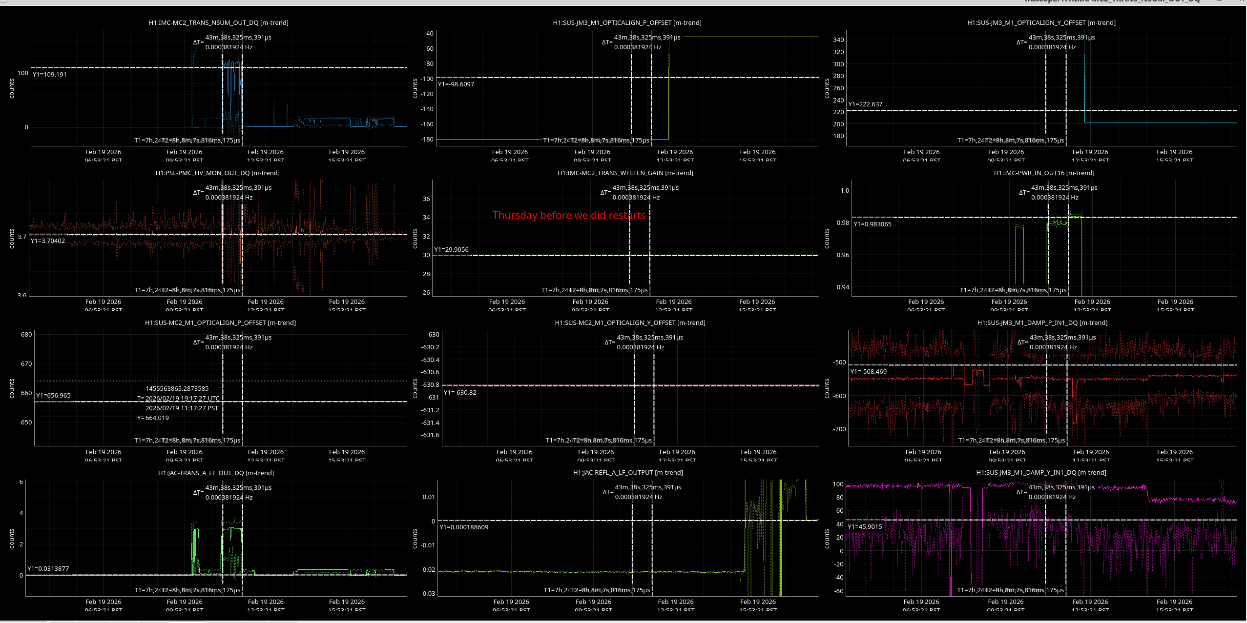
In the end, MC2 TRANS was centered reasonably well (right before the cursor in the attached), JM3 DAC output was O(1e7) while a 28 bit DAC's range is +-134e6.
Apparently we made the last step of JM3 PIT adjustment in the wrong direction at the time (we didn't notice because the WFS is very slow) and overshot. I steered it back later, now H1:SUS-JM3_M1_OPTICALIGN_P_OFFSET is -39 instead of -19 (second screen shot).
Anyway, this means that the alignment into HAM2 is good with more than a comfortable range left for JM3. No need to further refine.
One caveat is that the IM4 trans is totally off in PIT. But that's a downstream problem which we'll have to deal with later in HAM2. That should not prevent us from moving forward to close down the chamber.
The tasks listed below are described in different alogs.
JAC TRANS PD calibration
Last beam dump (alog 89249)
ALS beam path check


Summary: JAC TRANS PD well aligned, rough power budget done, ALS beam from PSL does not hit any wires or components before reaching its intended steering mirror in HAM1.
POWER BUDGET
Jason and I went into do some measurements on the TRANS PD path after 11am. We were unsure yesterday that this PD was well aligned after the laser window installation.
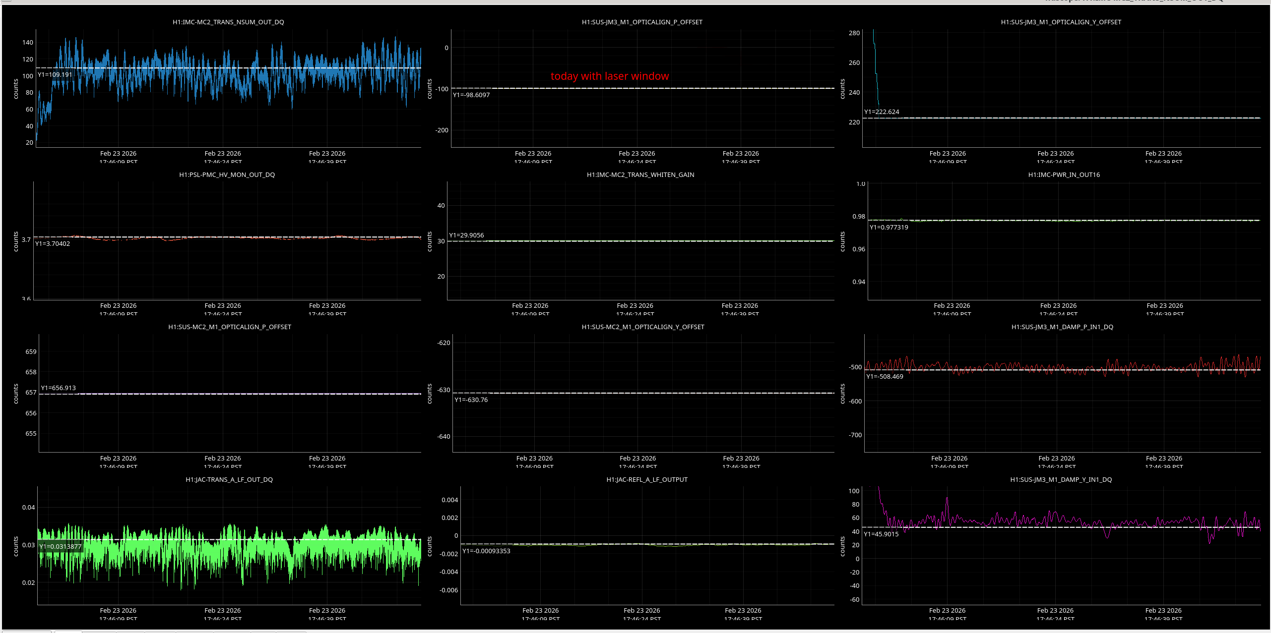
The beam going to the TRANS PD matches roughly what we expect with the uncoated laser window we now have as BS1. Here is a photo showing the power Keita and Jason were getting after swapping in the laser from yesterday (in the lower left plot).
There was approx 0.03 on TRANS PD. Previously with a HR mirror in place of BS1 we had ~ 3 on TRANS PD (see lower left plot on ndscope).
Keita did a calculation of the rough power reflected from BS1, assuming an AOI of both 40 degrees or 35 degrees (AOI should be around 39 degrees according to layout).
rp=tan(theta-phi)/tan(theta+phi)
theta is the AOI and phi is the angle of refraction,
phi = asin(sin(theta)/n),
n=1.4496 for fused silica at 1064nm.
rp(theta=40deg)^2 = 1.14%
rp(theta=35deg)^2 = 1.63%
This means that the beam is likely not clipping on the TRANS PD as the power on it seems to have scaled as we expect with the laser window installation.
To double check this and provide a calibration for this PD we did some power meter measurements in chamber.
We measured the output from the input side curved mirror of the JAC (Te2), with the PSL set to 1W output using the rotation stage (otherwise it is hard to see this beam on the card).
JAC Te2 = 2.7 mW
JACT_BS1 transmitted beam = 2.4 mW
JAC TRANS PD beam = 37 microW
This leaves us with 0.263 mW unaccounted for in transmission, this puzzles me.
We put the power out of the PSL down to 100 mW to measure the input power and output power in HAM1.
JAC input power = 115 mW
HAM2 input power/after HAM1 output periscope= 96mW
ALS BEAM CHECK
Jason opened the light pipe and checked that beam does not intersect anything int he new installed path before reaching its SM that directs it towards ISCT1.