J. Freed (with help from Marc and Fil)
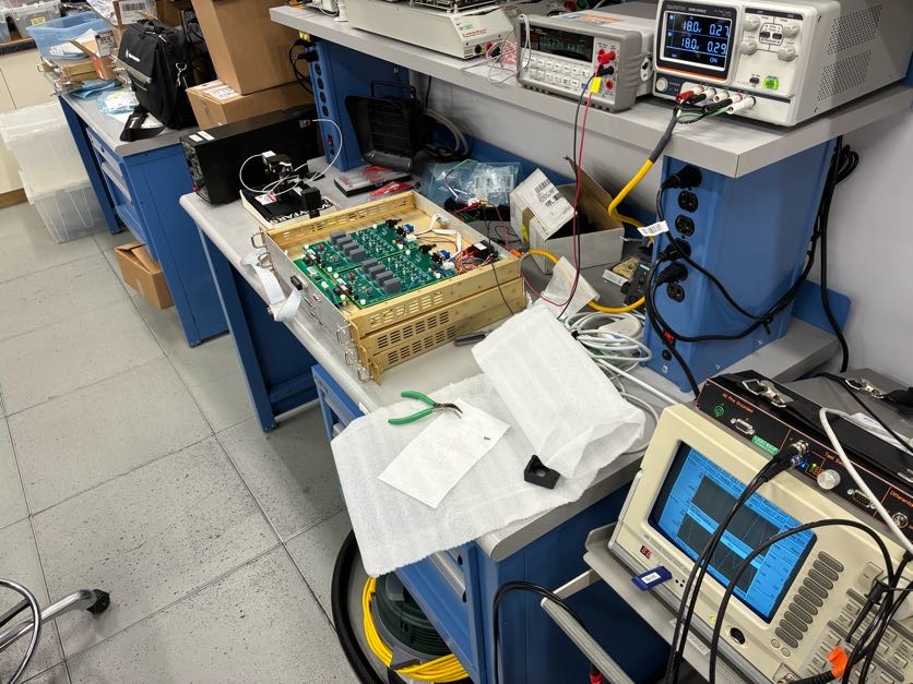
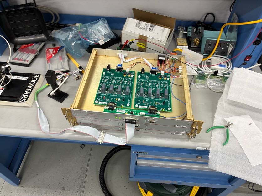
I tested the real wiring chain described in D2400111 from PD through the 3 variants of the TIA and it does follow exactly what is described in the link. There were 4 things of note that were found during this test.
1. All the whitening filters were switched "on" inside the TIA, however our final design document states that only the QPDs need whitening. As such the SPD boards S2500647 and S2500645 whitening switches were set to bypass. I logged this change in the E-Traveler.
2. The D1700116 silicone circuit board for the FFD-200 causes shorts. The main issue is the GAP 5000 pinholes on the PD side of the board. If the PD is flush with the board those pins touch the case of the FFD. Since the GAP pins are also connected to the cathode and anode, this causes the circuit to short. This is simple enough to test without taking out any PDs from the case. If there is "no" resistance between the case (ground) pin and the anode/cathode pins on the DB9 connector coming from the PD, then it is shorting and the system should not be turned on. There are 2 options suggested to fix this, either put insolation between the GAP pins and the FFD case or cut the GAP pins connection to the FFD anode/cathode. For this specific test, the issue was bypassed by putting in a tissue between the FFD and the silicone board.
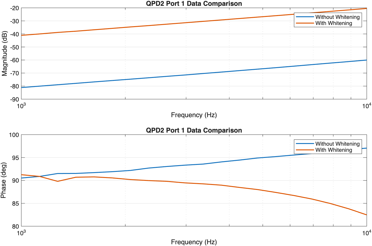
3. I tried to take transfer functions from all the PDs through the TIA, however the laser I used (the MIT ISC AM Laser) AM modulation was designed for 5 - 200 MHz, not the 4096Hz we are trying to use. As such, I suspect the harsh attenuation (~70dB at 4096Hz AOM_Attinuation.png) I measured was caused by the laser. So I decided it would be better to put off the transfer functions through the TIA until after SPI is built, then use our own laser AOM system to run the test. The laser was just left at DC and was used as the light source to see if signals on the PDs follow the correct wiring chain.
4. I used the laser to check that the signals on the PDs follow the expected wiring chain through the output of the TIA. Ex. Laser on Quadrent 1 of the QPD outputs a voltage on the expected pin on the output of the TIA. All pins were found to be correct.


We checked the production units, and they do NOT suffer from the shorts described in item 2 above. *phew* Great work Dean!
See details in LHO:89263.