jeffrey.kissel@LIGO.ORG - posted 14:33, Wednesday 25 February 2026 (89268)
Setting up New Fiber Coupled NPRO in Optics Lab: The NRPO and System Components Dry Run
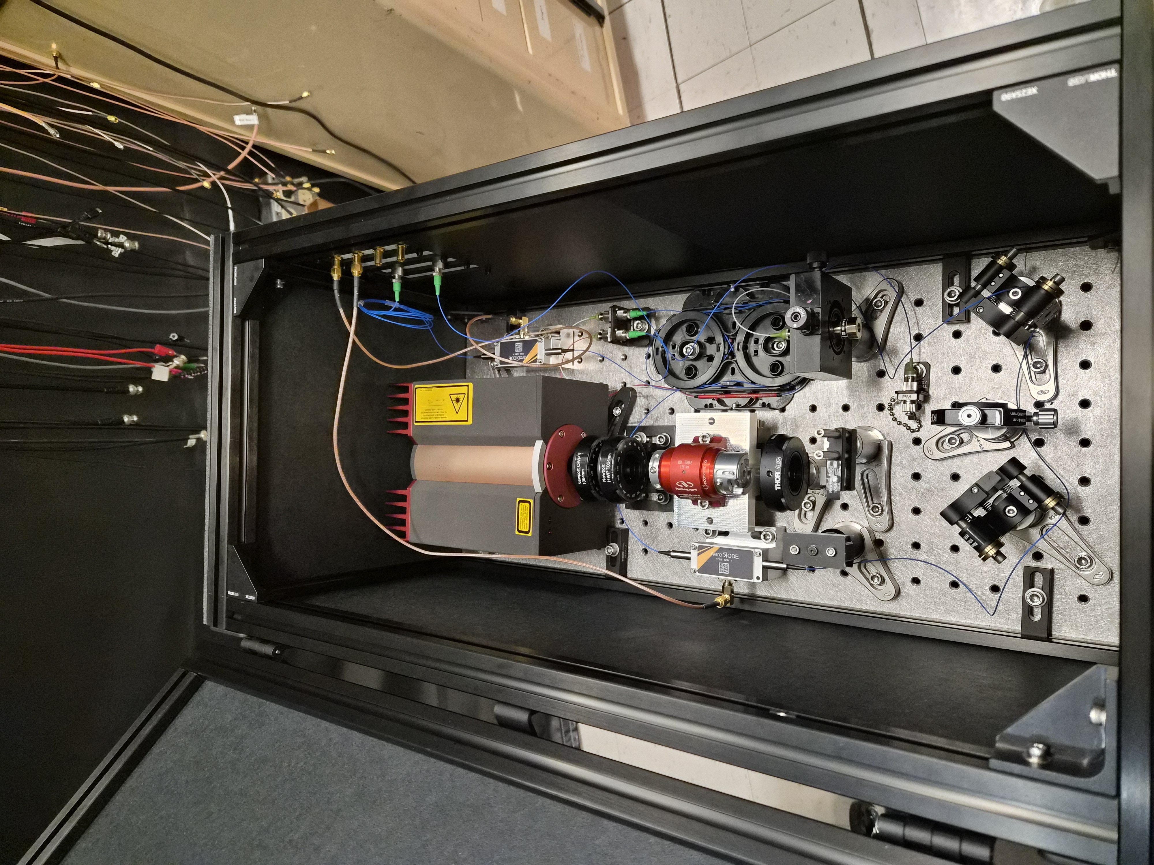
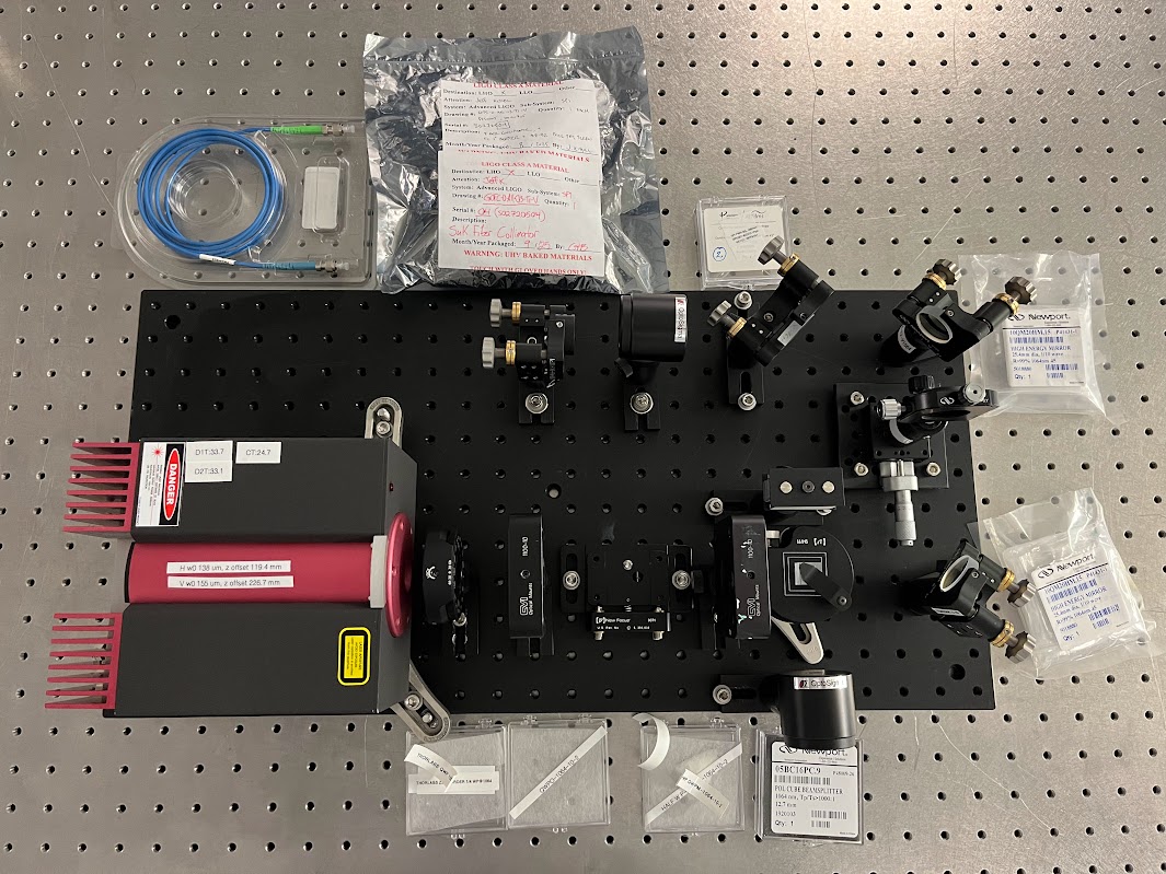
J. Kissel, R. Short, J. Oberling

This is the first installment of aLOGs documenting the setup of a new stand-alone 1064 nm NPRO laser system whose current "end game" intent is to provide ~100 [mW] of fiber-coupled p-pol light to the SPI laser prep chassis.

Step 1: Gathering materials, find what optics / mounts we had vs. what would be need, and physically layout the plan.

Jason lets Ryan and I know that there are three NPROs in the optics lab, two of which are PSL spares that cannot be used.
The remaining laser is S/N 1661, the laser used in the PSL during O3 which is *functional* but was briefly installed during O4 circa Fall/Winter 2024 then removed from use in the PSL because of reported glitching / incompatibility with the frequency stabilization servo (FSS) issues -- see the bottom of LHO:81391 for a nice summary, and LHO:81409 for record of its removal.

Inspired by the setup at Stanford Sina shared with us, we're looking to build up the following system to accomplish the goal:
    - NPRO (presumed to be elliptically polarized with Is / Ip = 5:1)
    - QWP (to linearize the polarization)
    - HWP1 (to rotate the polarization into horizontal)
    - FI (accepts horizontal linear polarization, to ensure back-reflections from down-stream components don't seed the NPRO causing glitches/mode hopes/frequency noise)
    - HWP2 (to rotate the FI output polarization into the desired amount of vertical polarization -- aka the desired amount p-polarization)
    - PBS (to filter out and dump the unneeded horizontal / s-pol light, and transmit the desired power of p-pol)
    - SM1 (one of two steering mirrors to align the beam into the fiber collimator)
    - L1 (the single-lens mode-matching solution to convert the NPRO beam into what the fiber collimator needs)
    - SM2 (two of two steering mirrors for alignment into the fiber collimator)
    - 50:50 PWR BS (45 [deg] AOI, optimized for p-pol; to provide a pick-off port for live power measurement)
    - Fiber Collimator

Ryan started with a 24" by 12" breadboard that was lying around in the optics lab. He build up a makeshift stand from three posts and dogs in the lower left corner such that the S/N 1661 NPRO projects the beam at 4" height. The 0.5" thick breadboard has a 1 inch hole pattern offset by 0.5" from the edges. I'll refer to this grid as having axes "m" and "n" where the m-axis are the "row" holes running from 0 to 23, and the "column" n-axis holes run from 0 to 11. I chose (m,n) breadboard coordinates so as to not confuse them with traditional beam profile coordinates of (z [propagation distance], x (transverse horizontal), y (transverse vertical)).

Thus, the NPRO being in the "lower left" means it projects the beam along the m = 3 row, and the front face of the NPRO is sitting at n = 8. We'll call this beam position z = 0.

We then proceeded to gather as much as we could of optical components from the optics lab drawers, and ended up with this pictured preliminary version of the setup.

Step 2. Power up the NPRO.
Here's were we ran into our first snag. Normally, NPROs are paired/tuned with specific controller boxes. However, when Ryan turned on the S/N 1661 laser with the S/N 1661 control box, the crystal temperature readback reported the temperature was quickly, linearly rising well beyond the desired temperature of 24.7 [deg C]. At ~42 [deg C], (but still below the internal automatic watchdog threshold of 50 [deg C]), Ryan knew something was wrong and turned it all off. He repeated the turn on just in case, and it did the same.

After conversing with Jason, we figure it's good enough to run with one of the other controllers for now, and in the mean time figure out how what's wrong and repair the S/N 1661 controller.

So, we're running with the S/N 7974, and things seem fine.
    Laser Diode Temp Setup:
        Diode 1 33.7 [deg C]
        Diode 2: 33.1 [deg C]
        Laser diode injection current readback 2.08 [A] (for both diodes)
    Crystal Temp setting is 24.7 [deg C]

We measured the output power*** with no optical elements at all as 1.820 +/- 0.005 W (not noisey, but a slow drift around).
Good enough! Onward and upward!

*** Power measured by ThorLabs power meter
	Model S302C
	SN 111149
	Sensing factor of 316.25 [mV/W]
	(last calibrated Feb 3 2012).
Images attached to this report