Jason and Jennie found that there's no digital signal coming out of JAC WFS DC no matter what.
I and Jason went to the floor, I flipped the gain switch of the WFS interface from low to high, but there was absolutely no response from any of H1:JAC-WFS_[AB]_SEG[1234]_INMON.
We confirmed that interface cables are connected from the IOT1 to the WFS interface (ISC-R1 slot U10), the interface is connected to the AA (ISC-C1 slot U30), and the AA chassis is connected to ADC5. These all agree with D1900511 floor wiring diagram. I even disconnected the cable coming to AA (ISC_373) and WFS DC signals didn't respond.
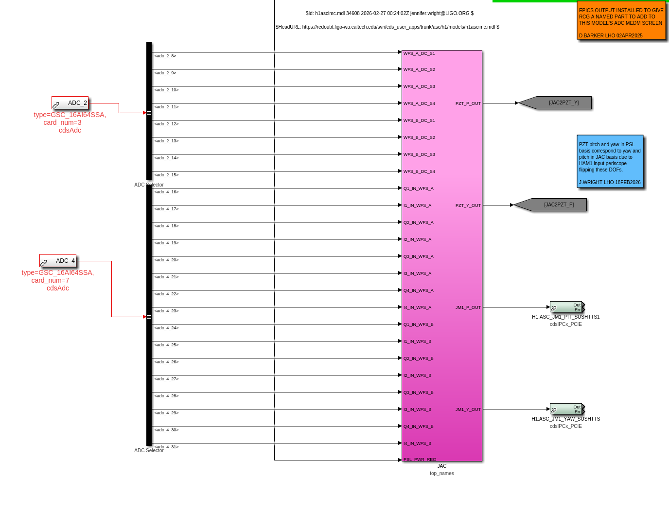
It seems that there's discrepancy between the floor wiring diagram and the model which was made according to T1100472 where JAC WFS DC signals are routed to ADC3 (see attached).
Good news is that RF channels are working.
As of now, the light is hitting WFSA and I was able to phase RF using an excitation injected into JAC PZT while JAC itself was locked. WFSB is dark now.
Jennie W, Jason O
Starting about 1.45pm, we went to check the alignment on the table after getting the ok from vacuum to let light into HAM1.
We could see light getting through the periscope but Jason tweaked the upper mirror to get the beam centred on the lower mirror.
Then we centred the mirrors M5, M7, BS3 and M8 to centre on each mirror and then align onto the REFL PD. The shutter and PBS1 were not in the beam.
We had some problems aligning the HWP/PBS combo while HAM1 was still in air but today Jason managed to align the PBS and the angle of the half-wave plate such that the power to the PD is maximised.
The beam dump for the off-polarisation is also aligned. We had to tweak BS3 and M8 to re-align onto the PD.
After this we went onto aligning the beam onto the WFS and placing beam dumps for the beams reflected from each QPD.
Even when WFS A looked well-aligned by checking with the card, we could not see signals on WFS A quadrants. See explanation above in Keita's log.
Jason left WFS B mis-aligned as the beam tilts up slightly and so we could not catch the reflected beam with the beam dump.
We didn't want to fix this as Masayuki is working on tuning the JAC length servo, so we don't want to move M7 now.
According to T1100472 ADC 5 channels 17-24 should be something called "LO_A_DC" and "LO_B_DC" but I can't find these ADC inputs hooked up to anything in h1ascimc or h1asc.
We can do a model restart to fix this (ie. hook up the JAC WFS DC readouts to channels on ADC5 instead of ADC3) on Monday assuming that is ok with Daniel/Dave.
JAC and LO WFS DC assignments are swapped between the channel assignment document (T1100472) and the wiring diagram (D190511).
Channel assignment: JAC WFS DC = ADC3, DB9_3 and DB9_4. LO WFS DC = ADC5 DB9_5 and DB9_6.
Wiring diagram: LO WFS DC = ADC3, DB9_3 and DB9_4. JAC WFS DC = ADC5 DB9_5 and DB9_6.
Assuming that the above is correct, you can do one of two things.
1. Swap cables on the AA chassis and update the wiring diagram.
2. Change the model and update the channel assignment.