Summary
The calibration of the PDH error signal and the feedback path was derived using the Guardian-based signal normalization. The normalized PDH error signal allows the optical gain to be calculated analytically. The transfer function from L_SERVO_OUT to the cavity length actuation was measured and modeled, separating the optical gain and the PZT actuator response.
Details
Normalized PDH error signal
With the Guardian normalization, the PDH error signal at L_SERVO_IN1 can be written as
V = x / (1 + x^2)
where V is the signal at L_SERVO_IN1, and
x = l / HWHM
where l is the cavity length fluctuations and HWHM is the cavity half-width at half-maximum.
Using the finesse F, the cavity HWHM is
HWHM = lambda / (4F)
At the lock point (x = 0), the slope of the error signal is
dV/dx = 1
Optical gain
Therefore, the optical gain is
dV/dl = dV / d(x * HWHM) = 4F / lambda
Using F = 125, lambda = 1064e-9 m, the optical gain becomes
dV/dl = 4.70e8 cnts/m
Error signal calibration
To convert the signal at L_SERVO_IN1 to cavity length, we apply the inverse of the optical gain.
Calibration factor = 2.128e-9 m/cnts
Plant measurement
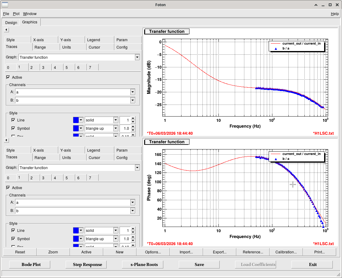
After locking the cavity with a provisional filter, the transfer function from L_SERVO_OUT to L_SERVO_IN1was measured and treated as the plant (see attached plot).
Since this plant includes both the optical gain dV/dl and the PZT actuator response, L_SERVO_IN1 was converted into meters using the calibration factor above before the measurement.
Also, the servo output is calibrated in V (and converted into cnts at the PZT_DRV filter). That means, the measured plant represents the transfer function from the PZT driver input to the actual cavity length actuation with the Unit of m/V
Plant model and actuator calibration
The optical gain and PZT actuator response are implemented in the servo model as FM9 and FM10 of L_SERVO.
In addition, a zpk(-800, 800) filter is included to emulate the phase delay.
The comparison between the model (FM9*FM10) and the measured plant (uncalibrated) is shown in the second plot. This response includes the PZT driver transfer function. That has two poles at 1 Hz and 400Hz, and one zero at 10 Hz. The DC gain estimated from the measured TF is 2.57 nm/V. This is comparable to the value measured with the scan of the JAC (2.97 nm/V).
Error signal normalization consistency
The error signal at JAC-L_SERVO_IN is normalized by the power at output of JAC_REFL_A_RF43. Therefore, once the guardian normalization procedure has been executed, the same calibration factor should remain valid.