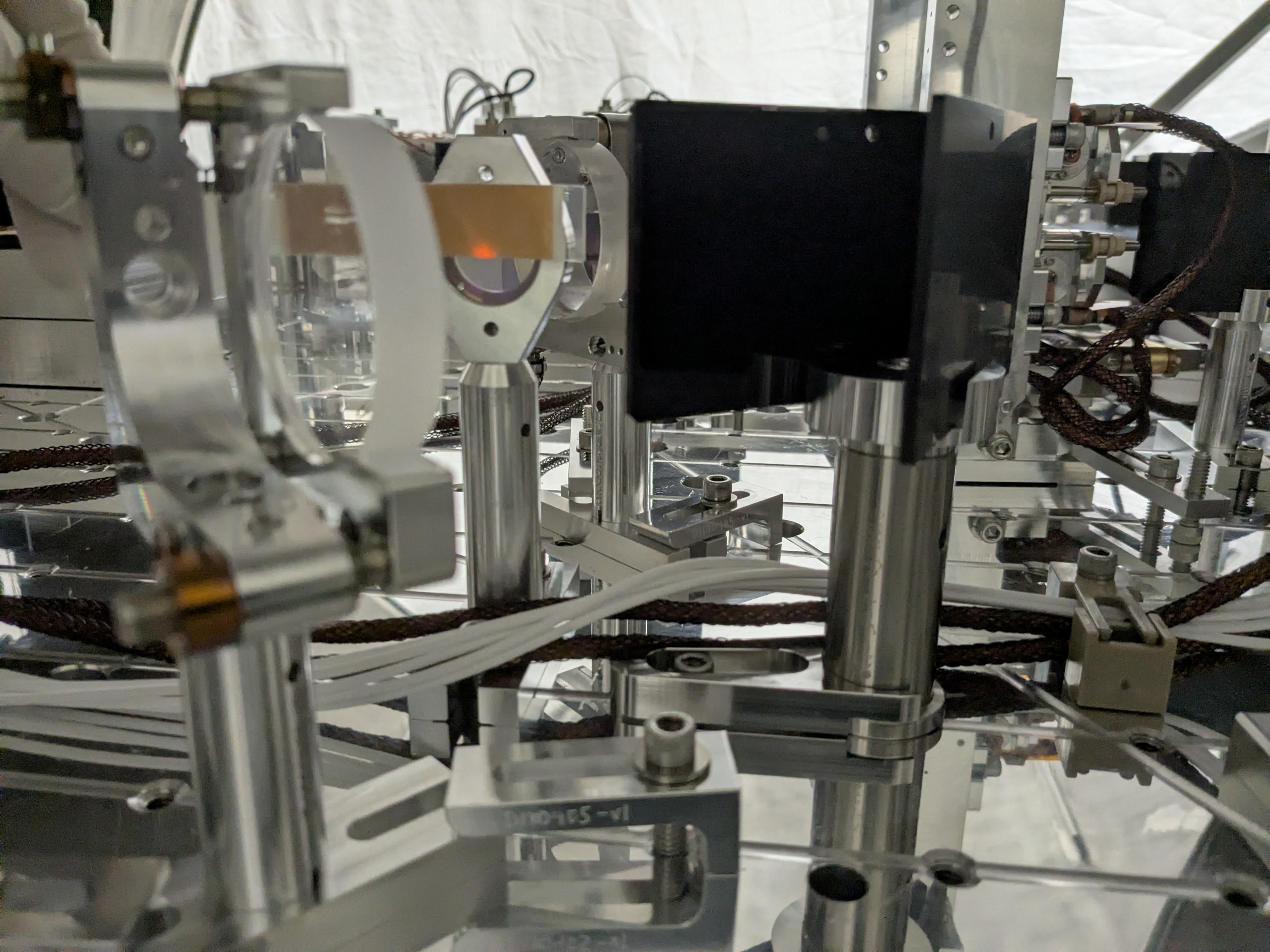
I've found that the pico mount for 50:50 BS on the REFL WFS sled in front of ASC REFL_A was loose and rotated counter-clockwise seen from the top by a huge amount (1st attachment, orange arrows show the direction of rotation). Our guess is that the BS mount was bumped when we were leaning into HAM1 from -Y door to work on the JAC output periscope. In general, it's hard to rotate the mount clockwise seen from the top even if the screw is not super tight (because the screw tends to be tightened), but it's easier to go counter-clockwise.
When this was found, the beam was hitting the +X-Y edge of the mirror, there was no clear reflection beam found so no beam on WFSA, but somehow the ugly transmission beam with lots of diffraction patterns was making it to WFSB.
We reverted the RM1 and RM2 bias sliders back to O4 level (RM1 PIT=-180, YAW=-57, RM2 PIT=890, YAW=-530) and I confirmed that the centering on the 2" lens was good. WFSA mount was screwed down tight to the post.
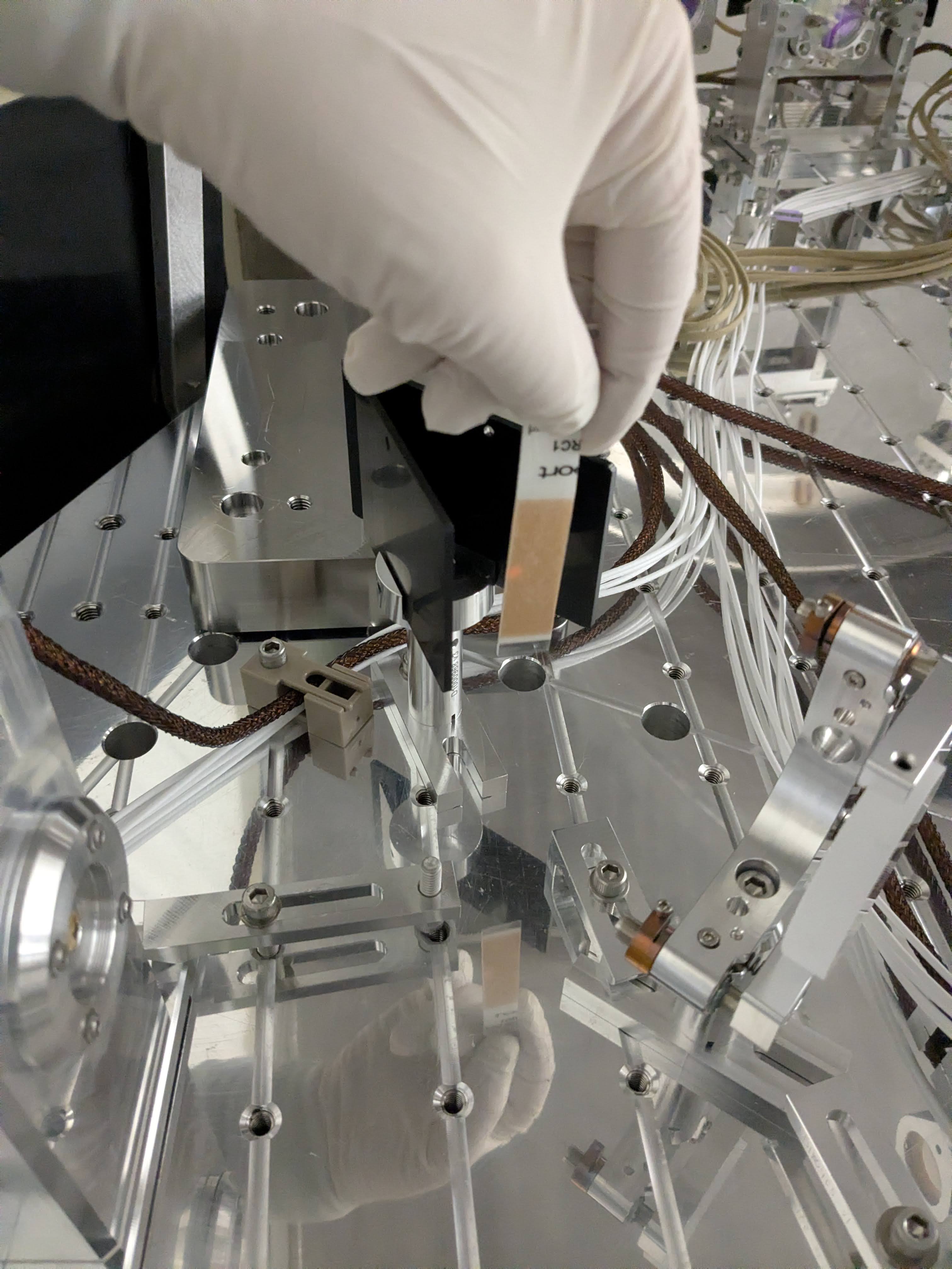
RM1 bias was adjusted further (RM1 PIT=-190, YAW=263) to roughly center the beam on WFSB.
At this point I looked at the beam on WFSA and it was still off mostly in YAW but there was also a large PIT offset. These were taken care of by adjusting the picos I've just screwed down.
I enabled the REFL WFS centering which worked right away. LSC REFL diodes are receiving almost equal amount of light. We'll have to make sure that the beam is not clipped on LSC diodes. Anyway, I relieved the ASC using RM sliders and ended up these numbers: RM1 PIT=-192, YAW=274, RM2 PIT=910, YAW=-532.


Afternoon: Done with the REFL path
Making sure that the beam is centered-ish on the LSC sensors
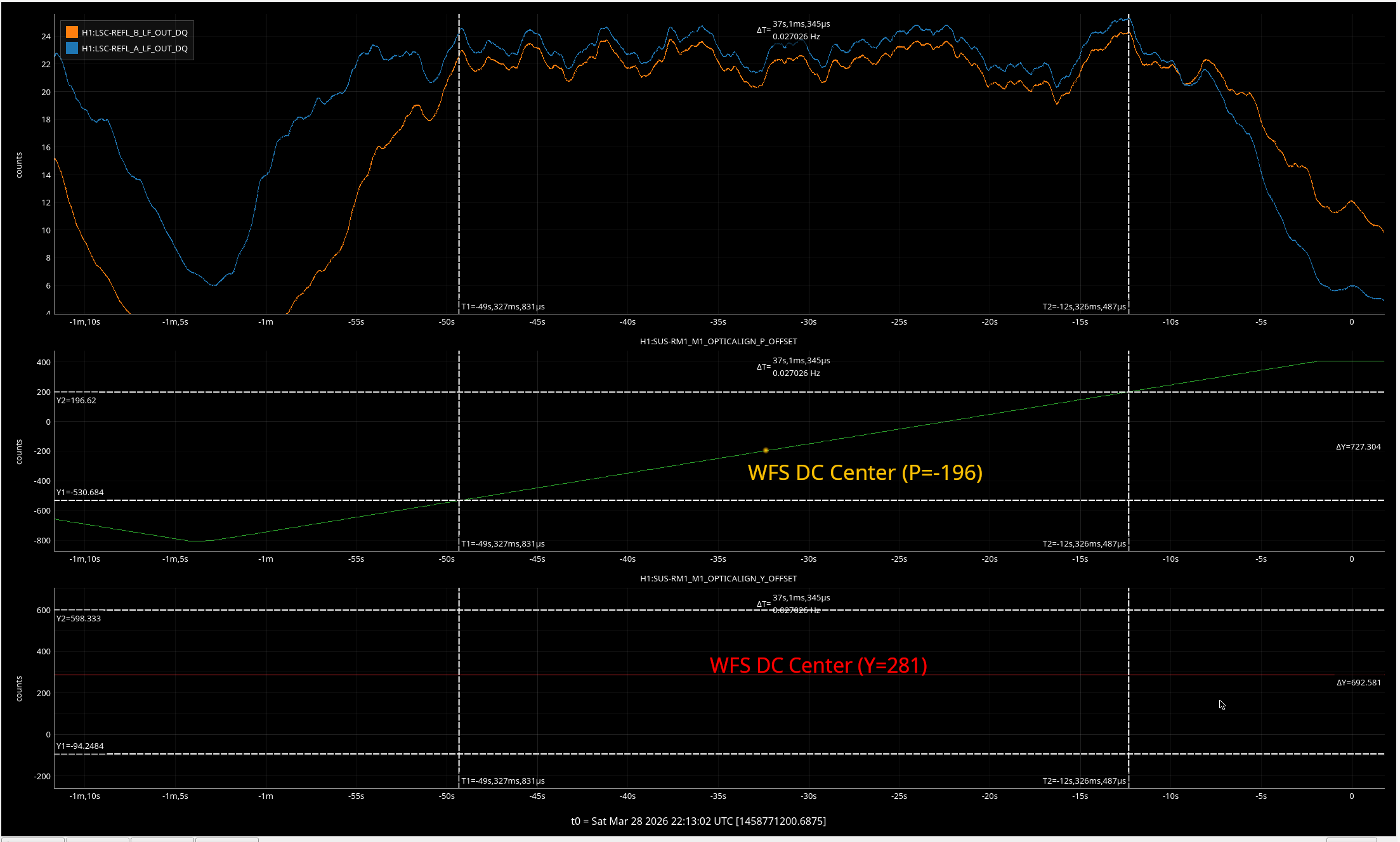
We enabled the WFS DC centering, relieved the WFS output by RM sliders, disabled the WFS centering. Then scanned RM1 in PIT to find out where the LSC REFL A and B DC starts to fall off, and make an average position in terms of RM1 PIT offset ("plateau center"). In general the plateau center is not the same as WFS DC center.
Use the common pico for the REFL LSC sensors to make the plateau center come closer to the WFS DC center. See the 1st attachment.
Repeat the same thing for YAW. We noticed that LSC REFL B is not exactly the mirror image of REFL A, mostly horizontally, as you can see from the 2nd attachment. If they are, we expect both to start falling at the same time but they don't. To fix that we need to touch up the non-pico 50:50 splitter that steer half of the beam to REFL B, but we chose not to do it because the scan range you see here is huge, and beam will totally fall off of WFSB before LSC REFL A and B starts falling.
After all of these and minor tweaks here and there, we ended up with: RM1 P = -196, Y=281, RM2 P=910, Y=-490.
Tilting WFSA in YAW
I checked the beam position along the REFL path and unfortunately the reflection from WFSA was hitting the mirror mount. I tilted the WFS clockwise, paying attention NOT to change the optical path length significantly. After this, Jason and Jennie used pico to steer the beam back to the center of WFS. I confirmed that the WFSA reflection goes into the beam dump.
Final check
I rechecked the beam position along the REFL path. Nothing was grossly off-centered except for 1" mirrors and BS on the WFS sled (this was always the case).
On M2, RM1 and M5, the beam position looked OK though it was hard to say anything quantitatively. No picture for these.
1" lens for the LSC censors, 2" lens on the WFS sled as well as 1" lens on the WFS sled looked good.
Reflection of all LSC and ASC REFL sensors fall on the beam dumps.
Pictures will follow.
No POP check yet
I looked at the POP path too but it wasn't flashing and it was already 4PM so we gave up. We'll continue on Monday.


Correction: In the above alog text, "LSC_REFL_B_ghost.jpg" points to the picture for REFL_A ghost beam. This is the correct one: LSC_REFL_B_ghost.jpg.