Summary: A thermal lens resulting from using 2 Fused Silica windows as attenuators in the CHETA system should not effect the profiled beamsize.
We are considering using 2 Fused Silica windows at 45 degrees as absorping attenuators at the outputs of the QCL during beam profiling to stop back reflections which we believe are currently damaging the units. We plan on using 2 windows to prevent a beam displacement so the path doesnt have to be altered. During this process we require atleast 7mW on the thermal profiler to accurately profile the beam.
The attenuation through each 1mm window assuming using a loss factor of -28e6dB/km at 4.6um would be as follows:
Power after first window: 0.398W
Power after second window: 0.158W
Power reflected back through both windows: 0.0251W
This shows there will be non-neglible absorption so some quick modelling has been completed to demonstrate that this thermal lens would not have a significant effect on the system.
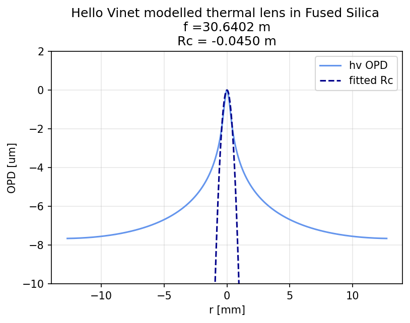
I have used the finesse Hello Vinet implementation to model both the thermo-refrative and thermal expansion induced thermal lenses, assuming 2W of QCL power is absorbed in the substrate. This will be an over estimate as HV assumes that Pin ≈ Pout and that the absorbed power is much smaller than Pin.
A radius of curvature was found from the HV OPD by completing an overlap interval with 2,0 and 0,2 modes.
Assuming worst case scenario of 2W of absorbed power and an beamsize of 300um (approximately the waist of a nominal QCL unit) there is an induced thermal lens of f =30.5273 m Rc = -0.0451 m. To determine the effect on the q-parameter of the beam I have assumed both glass windows act as a lenses with this focal length and use ABCD matrics determine the change in q. This change in q is similar to the measurement error of these q factors and when propagated through to the ITM changes the beam size by less than 1%. This calculation for every unit is given in the table below using these yaml files.
| Condition | q (x) | q (y) | w at ITM x (m) | w at ITM y (m) | q at ITM x | q at ITM y |
|---|---|---|---|---|---|---|
| 0918 | ||||||
| current system | −0.234 + 0.113j | −0.295 + 0.098j | 0.05346 | 0.05747 | 35.977 + 0.663j | 35.634 + 0.563j |
| with lens | −0.231 + 0.110j | −0.290 + 0.094j | 0.05426 | 0.05854 | 35.994 + 0.644j | 35.664 + 0.543j |
| 0920 | ||||||
| current system | −0.129 + 0.071j | −0.155 + 0.059j | 0.04794 | 0.05408 | 36.818 + 0.866j | 36.576 + 0.671j |
| with lens | −0.128 + 0.069j | −0.15367 + 0.05782j | 0.04828 | 0.05451 | 36.830 + 0.854j | 36.594 + 0.662j |
| 0919 | ||||||
| current system | −0.186 + 0.096j | −0.227 + 0.072j | 0.04737 | 0.05492 | 37.546+0.920j | 37.221 +0.673j |
| with lens | −0.184+ 0.094j | −0.224 + 0.070j | 0.04791 | 0.05566 | 37.564 + 0.900j | 37.251+ 0.656j |
| 0851 | ||||||
| current system | −0.180 + 0.069j | −0.224 + 0.063j | 0.04887 | 0.05462 | 36.143 + 0.670j | 35.772 + 0.545j |
| with lens | −0.178 + 0.067j | −0.221 + 0.061j | 0.04928 | 0.05515 | 36.316 + 0.795j | 35.896 + 0.620j |
edit: fixed LLO numbers with updated parameters