J Freed, M Pirello,
We continued the progress to install the SPI RF chain as well as measured the 80MHz RF power along key points along the chain.
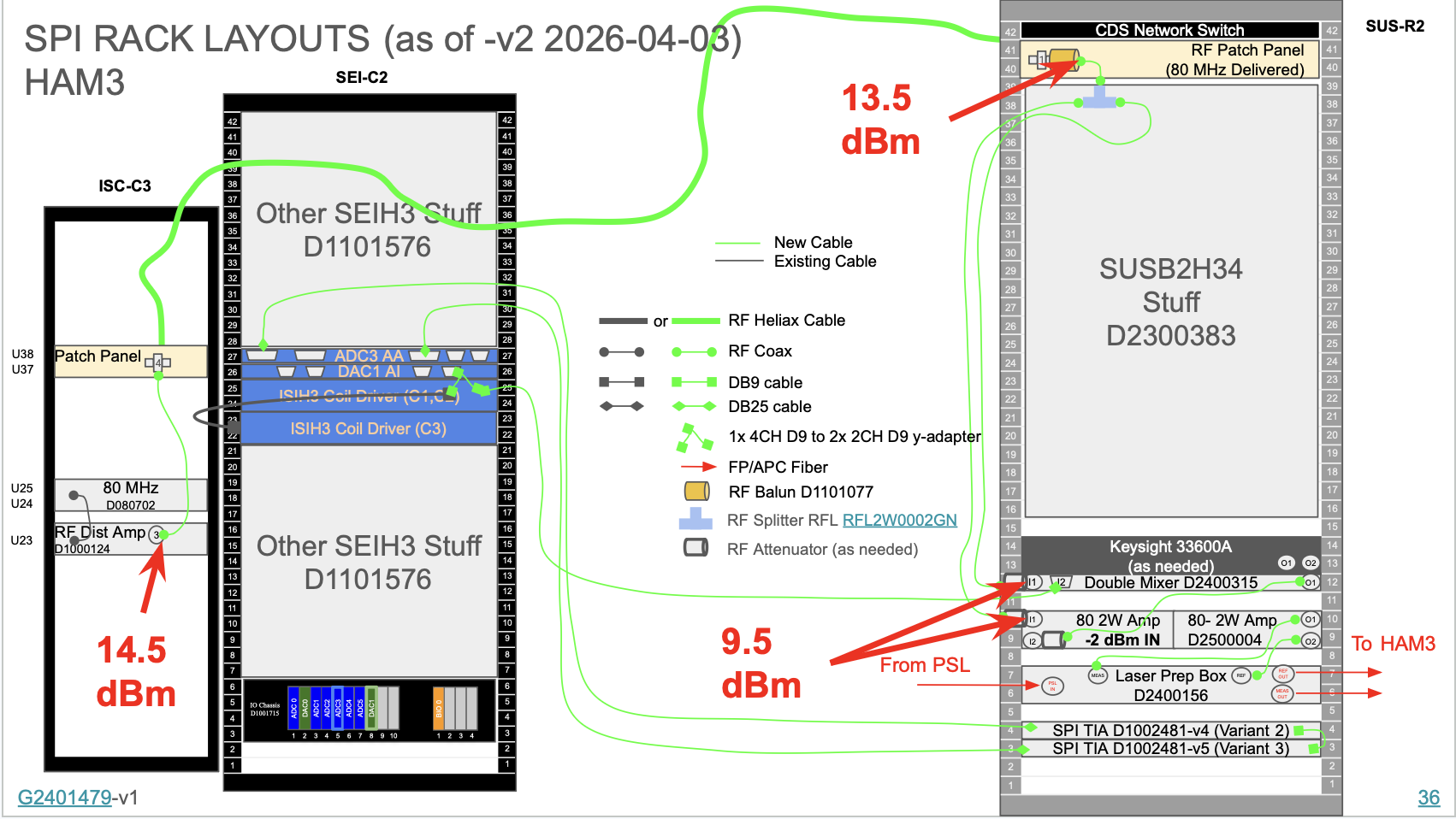
SPI_RACK_LAYOUT_SUS-R2.png Shows the schematic of the rack layout for SPI in HAM 3 as well as measured power along that chain. We currently have the entire chain installed to just before the 2W amp. The main thing of note is that we have more power than even our most optimistic estimate. (We were expecting about 5dBm, MAX 8dBm, but we have 9.5dBm). The Heliax cables are much more efficient than we expected. As such next on the list is to install attenuators such that we get the power we expect.
IMG_0627.jpg Shows the current Balun/Spitter set up. There is not really a good place to put the splitter on the SUS-R2 rack as the Patch Panel "walls" prevent using zip-ties or velcro to attach the Splitter on the sides of the SUS-R2 rack. Above the patch panel is the top of the rack; and below cables are in the way. As such, the least intrusive way is to attach the splitter to the balun (The transformer that converts the balanced Heliax cable to the unbalanced coax N-type cable), and add some strain relief on it. Not sure how effective this strain relief is but its better than nothing.
Marc also set up the 18V and 24V DC that powers the Double Mixer and other chassis that will eventually be installed.
Next steps:
1. Add attenuators such that the power going into the 2W amp would be correct.
2. Do phase noise measurements on the output power of the Double Mixer and see if anything has changed since 90179
3. Test if instead of Attenuators we can attenuate the power output of the double mixer by adjusting the input voltage of the 4096Hz signal from the CDS that goes to the Double Mixer