jeffrey.kissel@LIGO.ORG - posted 10:48, Friday 22 May 2026 - last comment - 11:20, Friday 22 May 2026(90313)
2026-05-20 SPI Pathfinder Update: REF IFO Aligned but only 35% Efficiency and Issues with QPDB Reflection
J. Kissel
(Belated aLOG)

Here's the continued summary log of what was done on the SPI pathfinder, up to Wednesday Afternoon 2026-05-20.
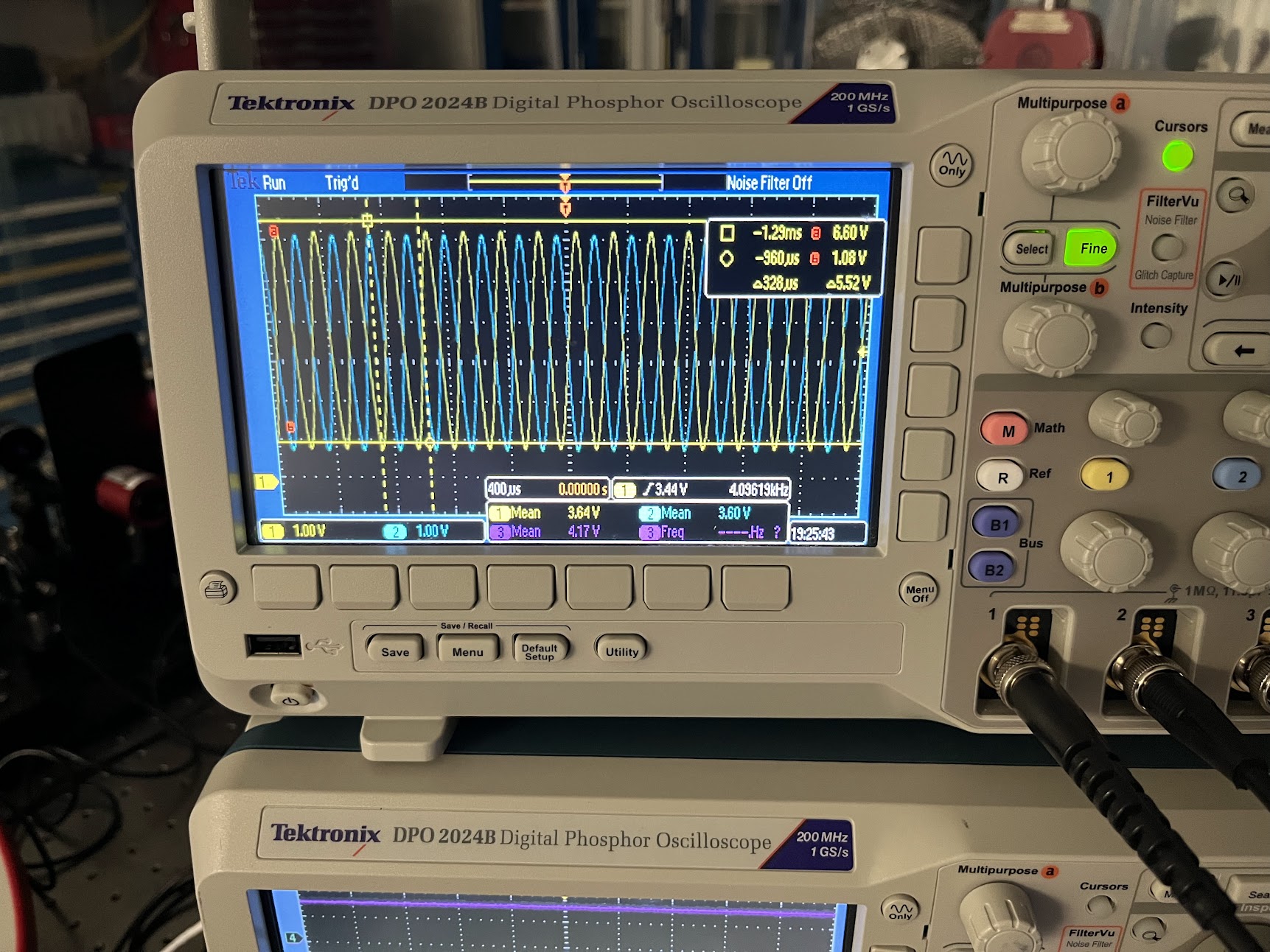
    - Unshuttered laser for the morning (still on overnight, so well past its thermal transients), with o-scope still reading out the MEAS IFO with 400 [usec/DIV] and found the efficiency low.
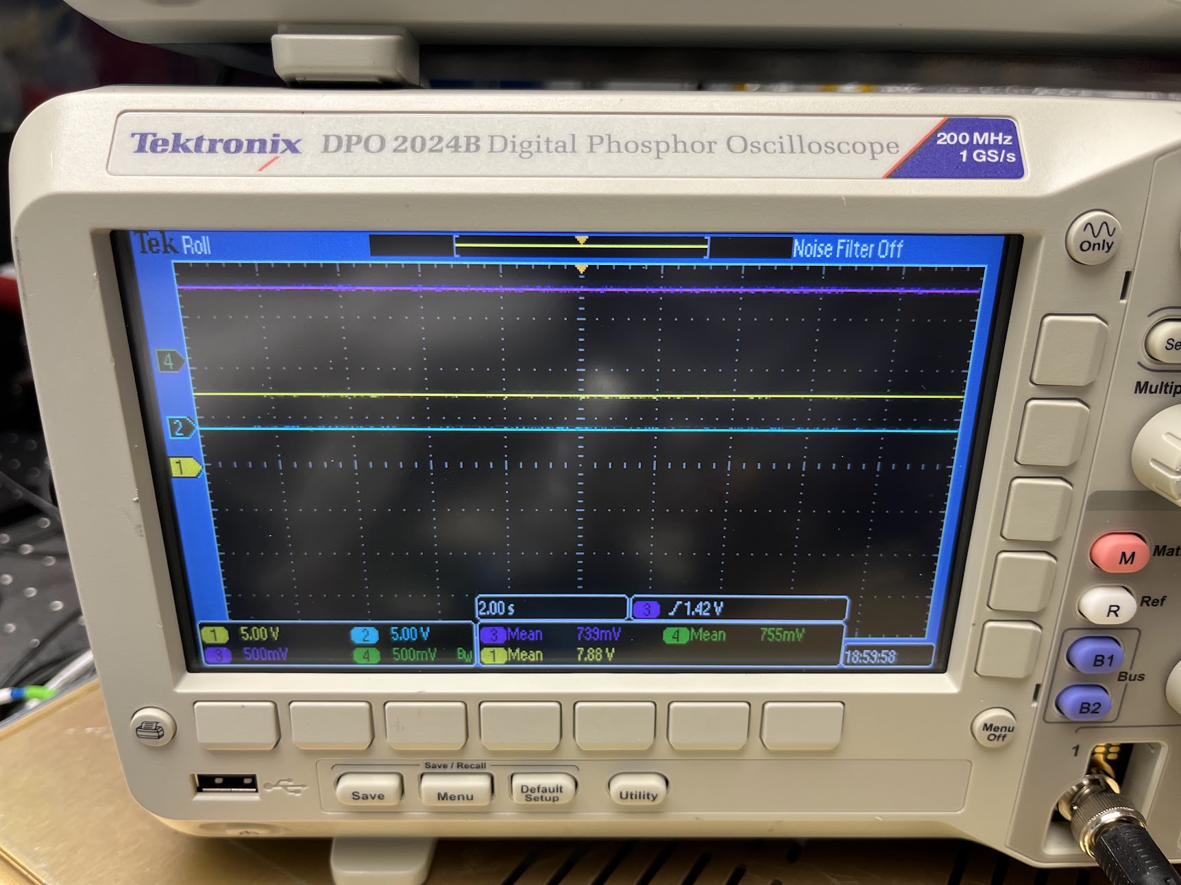
    - Looked around for a bit, still get prepped for the day, and I turn around that MEAS IFO efficiency has recovered. Very weird. Set the scope to measure the MEAS A and B efficiency and input power monitors on 40 [sec/DIV] to gather a long, 400 [sec] = 6.6 [min] trend while I worked on aligning REF IFO. Found the this true
        . [FUTURE JEFF] Note, this was true *before* I had issues with OL_QPD_B alignment and swapped out the dumps for big dumps (see below), making the "is the beam clipping?" potential for it being the issue questionable.
    - On to continued migration of components, now the MEAS path into the REF IFO.
        . Locked down set screws for R_B1 and R_B2 (R_F1 and R_M1 already locked). Since both REF paths are are aligned into the REF and MEAS IFOs, we want to fix it as the LO / reference for the IFOs.
        . Dumped REF beam path into REF IFO.
        . Installed and aligned M_B2 using holes 90 and 91. (Again: "aligned" or "confirmed alignment" means confirming alignment thru irises with IR camera, as well as maximizing power through irises with power meter.)
        . Installed IFO_PWRIN_MEAS PD and dump D_IFO_PWRIN_MEAS.
        . Confirmed function of PD.
        . Confirmed alignment of beam onto IFO_PWRIN_MEAS PD.
        . While checking functions of PDs, went over to OL_QPD_B (never checked this prior to aligning MEAS IFO on 2026-05-19), and found its reflection missing the D2400368-v1 assembled as designed. This is assuming that because I already had ~72% efficiency on the MEAS IFO, that I didn't want to move any mirrors/beam splitters. [FUTURE JEFF] THIS IS AN ERROR IN MY ALIGNMENT PROCEDURE (On 2026-05-19 I should have used M_B1/M_M1 to align to OL_QPD_B, THEN set the alignment of OL_QPD_B to hit the dump D_OL_QPD_B dump location as designed).
            :: Increased beam dump "catcher" plate of the v-dump size to 1.16" x 1.16" plate, in first attempt to catch the beam
            :: THEN physically rotated the QPD housing in YAW, centered the QPD signals on the incoming beam, but that yawed the reflected beam even further away (in -Z) from the designed D_OL_QPDB location. [FUTURE JEFF] Further indicating the issue was with the incoming beam, not the QPD.
            :: So, I increased the dump "catcher" and "receiver" plate to 1.58" x 1.58" plates.
            :: This made getting the beams around this big plates really challenging, but I was able to get something that worked, with the ~5 [mm] diameter beam spot on the card not clipping (acknowledging that I don't know the real beam diameter other than "it should be 2 [mm] all over the transceiver").
        . Moved on, and migrated M_M3 over confirming alignment with holes 93 and 96.
        . With MEAS beam now into R_B3, confirmed alignment with irises with holes 100 and 97.
        . Unblocked REF path into REF IFO and began to search for heterodyne beat note. Having much tougher time than with MEAS IFO.
        . Remembered Bram trick of temporarily removing IFO_REF_A to project both REF and MEAS beam further off the board to confirm far-field alignment. Was indeed clean misalignment of beams in far field.
        . Adjusting only MEAS path by walking M_B2 (for near field adjustments) and M_M3 (for far field adjustments), was able to find the beat note on IFO_REF_B.
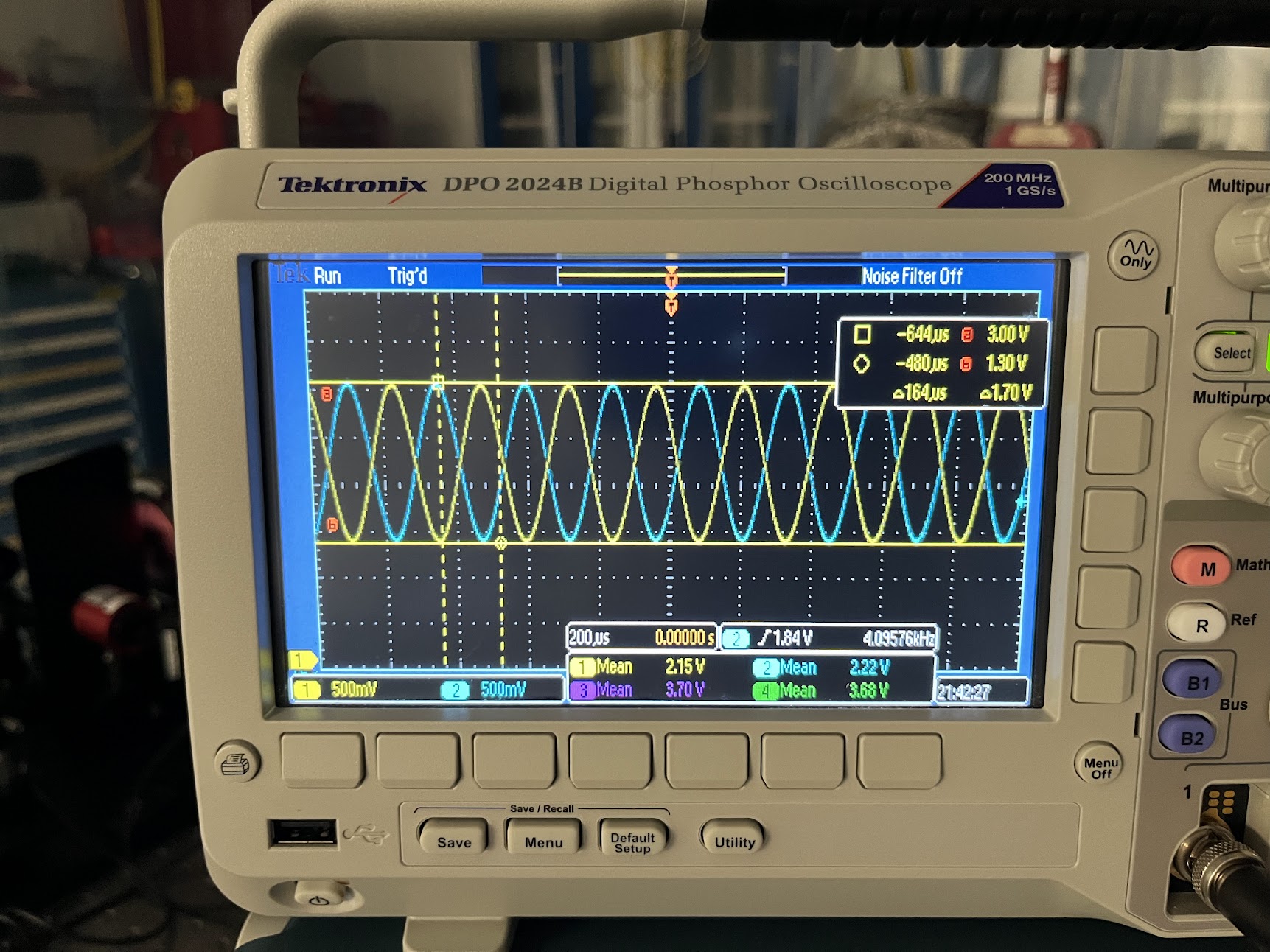
        . Re-installed IFO_REF_A PD, and maximized beatnote as best I could, but only got 35%.

            Max = 3.00 [V]
            Min = 1.30 [V]
            Amp = 1.70 [V]
            Mean = CH1 2.15 [V], CH2 2.22 [V]
            Efficiency = Amp / (2*mean)
	        CH1      1.70/(2*2.15)= 0.395 % yuck!
	        CH2      1.70/(2*2.22)= 0.383 % yuck!
        . But this is just a "reading off the scope" efficiency, wanted to make sure this wasn't dramatically influenced by dark offsets, so spend some time gathering PD DARK offsets. All SPD dark offsets are in the 15 [mV] level FAR below the now-excellent signal voltage levels.
        . Also noticed, with both IFOs functional and up on the o-scope, with it triggered on the REF IFO,
            :: Phase drift of MEAS IFO w.r.t. REF IFO.
            :: Sensitivity of the IFOs to flicking of either MEAS or REF fiber.
    - Resolving to take this offline to talk to the SPI crew about it, I re-dressed up all cabling.
        . Found picomotor cable was mounted in the Cable Table bracket upside down, making the map of which quadrupus leg goes to which pico-actuated mirror challenging, so I fixed that.
        . Hooked them up as designed (mirror names == D2400107; pico cable == D2400342; pico driver board D1100326):

            :: M_M1  > J2  > Pins 12,13,24,25 > furthest right when looking at the open D25 connector as the boat floats (with all pins to the left) > Pico Driver page 5, D25-J2 CH5
            :: M_B4  > J3  > Pins 10,11,22,23 > 2nd right > Pico Driver page 5, D25-J2  CH6
            :: M_M2  > J4  > Pins 8,9,20,21   > 2nd left  > Pico Driver page 5, D25-J2  CH7
            :: Spare > J5  > Pins 6,7,18,19   > furthest left (where all the missing pins are > Pico Driver page 5, D25-J2  CH8
        . Confirmed all cables went "up first," with a soft-bend to breadboard level, and completely clear of all beams.
        . Confirmed IFO_MEAS_A cable is neatly threaded through the middle of the periscope mirrors, but doesn't interfere with the mechanical motion of the periscope
        . Confirmed all cables were clear of -X perimeter so as to not interfere with installation shelf cylinders D2500142
        . Confirmed all cables were clear of the utility holes consumed by SLIC shroud D2400106
        . Confirmed all cables won't interfere with installation handles
        . Confirmed all cables won't interfere with attaching / reattaching optical fibers.

But at least, the victory from today is : The D2400107-v4 board is completely migrated over to the D2400107-v5

At the end of the day the board was completely migrated, but I now had a list of issues to now tackle ([FUTURE JEFF] prioritized by importance):
    (1) Low efficiency of REF IFO.
    (2) Beam dump for QPDB. Is this good enough? How can I test quantitatively? Could move rotate the housing back, but -- won't the position of this reflected beam change once we get the real return MEAS beam, and we want "if centered on the QPD, then IFO will heterodyne" as an alignment reference?
    (3) Breathing of heterodyne efficiency on MEAS IFO (only MEAS IFO, REF IFO is rock-soiid).
    (4) P-pol transmission dependent on physical position of optical fiber
    (5) Reflection of PWRIN_REF. Should I crack the enclosure to try to fix it?
    (6) Phase drift of MEAS IFO w.r.t. REF IFO.
    (7) Sensitivity of the IFOs to flicking of either MEAS or REF fiber.

[FUTURE JEFF] After discussing with the team (in order of how to address the issues):
    (4) Fiber polarization state output dependent on fiber position. Check the tiny set screws on the fiber collimator again, make sure they're secure, but not too secure.
    (2) QPDB reflection dumping. I didn't follow procedure here, and that has caused a ripple effect. Fixing M_M1 alignment into QPD B is the way to go. That should solve the QPD B reflected beam issue, and thus any potential for clipping, and might clean up (3), BUT, before you do that,
    (1) Low REF IFO efficiency might be an issue with the alignment again. 35% is unacceptable, we need both IFOs above 75% at least. Maybe you need to revisit the whole MEAS path alignment, confirming spot position on PWNIN_MEAS, since that confirms M_F1 alignment. If it's off, realign the whole MEAS path and that might clear up the issues with the REF IFO and QPDB. If the PWRIN_MEAS alignment is good, then triple check that you've not put in any optics backwards.
    (5) PWRIN_REF PD reflection dumping. This can be a last issue fixed, but everyone votes to go into the PD and fix it albeit using the utmost of caution to protect the PD.
    (6) Phase drift between MEAS and REF IFOs -- not a big deal. Likely air-currents. Try waiving your hand over the IFO and seeing it you get a wiggle to confirm.
    (7) IFO sensitivity to fiber flicking -- this is why we have two IFOs and subtract the signal, to remove exactly this kind of fiber "acoustic noise" coupling. Nothing to solve here.
Images attached to this report

Comments related to this report
Pictures of the QPD Dumps

- Pic #1
    QPD alignment signals BEFORE yawing the enclosure, confirming just yaw is the issue.
- Pic #2
    QPD alignment signals AFTER yawing the enclosure.
- Pic #3
    1.16x1.16" "catcher" Beam dumper, prior to moving QPDB enclosure in yaw, looking at IFO_MEAS_B
- Pic #4
    Top down view of D_OL_QPDB prior to moving QPDB enclosure in yaw.
- Pic #5
    Views of 1.58" x 1.58" after installation.
- Pic #6
    Beam position on "catcher" dump plate.
- Pic #7
    View of tight clearance of beam into IFO_MEAS_B.

DON'T DO THIS, JEFF.
Images attached to this comment


Pics of Picomotor Quadrapus D25 Orientation Flip:

This is of the Quadrapus D2500342, S2500513.

- Pic #1
    As I found the DB25 end in the Cable Table Bracket, having not been touched since Jim/Bram originally cabled it up on 2026-03-19.
- Pic #2
    After flipping the DB25 end in the CTB.
- Pic #3
    Same as Pic # but labeled.
Images attached to this comment


Pics of MEAS IFO efficiency drift / changes over time

Here's some photos showing the "drift" in efficiency I'm talking about.
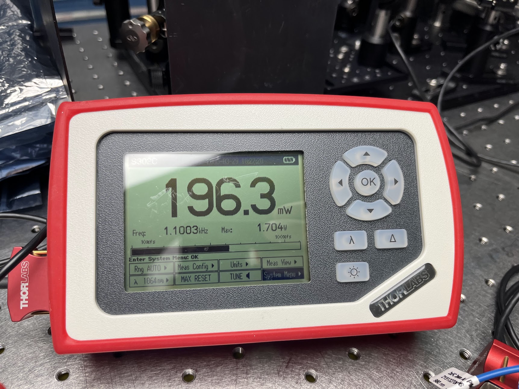
The first three photos: IFO BeatNote (400e-6 [sec/DIV]), InputPower, and NPRO Power.


The second three photos show the same thing 15 minutes later, with no change to the system but the efficiency is restored to the ~72%: IFO BeatNote (400e-6 [sec/DIV]), InputPower, and NPRO Power

The last three photos show the time-zoomed out 400 [sec] trends (40 [sec/DIV]) of the MEAS IFO efficiency as I was aligning the REF IFO, one at 10:56a and one at 11:19a PDT.
Images attached to this comment