jeffrey.kissel@LIGO.ORG - posted 22:12, Monday 25 May 2026 (90332)
2026-05-22 SPI Pathfinder Update: Two Steps Forward, One Step Back
J. Kissel, [S. Koehlenbeck remotely supporting]
(Belated aLOG)

Working with Sina over zoom, we tackled several of the issues reported in the last update (LHO:90313). In the discussion below, I use the same numbers as the issue list from the last update; they were prioritized, so I tackled things and had successes (and one failure) in that order.

The good news first:
    (1) FORWARD The issues with the low (then 35%) efficiency on the REF IFO were merely that I hadn't spent enough time walking the beam around. In the end, without adjusting the REF beam's input alignment at all, I was able to lock down the alignment set screws M_B2 and M_M3 which steer the MEAS beam into the IFO, while having IFO REF A reporting 99.0% efficiency, and IFO REF B reporting 97.2% efficiency. Very very excellent.
        Final answer
             (both traces at 1.0 [V/DIV])
             (only measurement of positive leg, not fully differential)
             (room lights and clean room fan off)
	     o-scope measured PEAK to PEAK (i.e. amplitude AMP) REF A and B = 4.04 and 4.12 V
	     o-scope measured MEAN: REF A/B = 2.04 and 2.12 V
	     Efficiency AMP / (2*MEAN):
                 REF A = (4.04 / 4.08) = 0.99
                 REF B = (4.12 / 4.24) = 0.972
    Attachment 1 shows a picture of the o-scope with evidence of these numbers.
    Let's hope this sticks -- it gives us a LOT of confidence about what these IFOs (and laser delivery system) are capable of once alignment has been optimized and and other issues have been mitigated. I also still see no evidence that the REF IFO efficiency "breaths" on the ~minutes time scale like I've seen with the MEAS IFO.

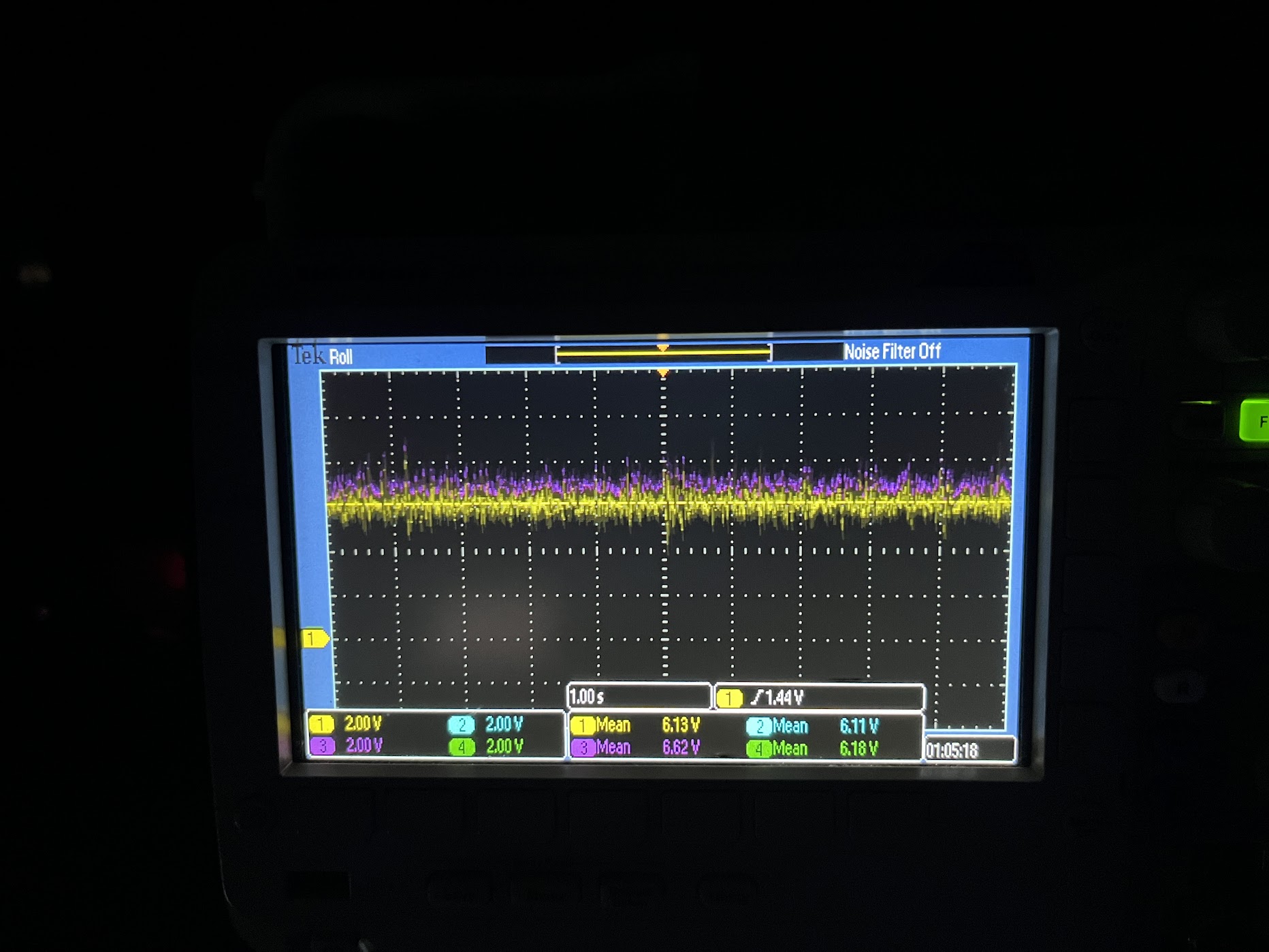
    (2) FORWARD Speaking of the MEAS IFO, along its MEAS beam path I addressed the issue with QPD B's reflection being wildly off in yaw. I was able to adjust the physical yaw position of OL_QPD_B with the slop in the enclosure's bolt holes such that the QPD reflection landed comfortably on the D_OL_QPD_B dump as it was originally; QTY 2x of the 1.0 x 0.75 [inch] plates (D1800140 Type 07). Said differently for clarity: I swapped out the QTY 2x of the 1.68 x 1.68 [inch] plates I cobbled together that was causing potential clipping issues (LHO:90315. I then centered the beam on the QPD using M_M1 as the steering mirror and and the QPD readout voltages as the metric for "centered."
        Final answer
            (all traces at 2.0 [V/DIV])
            (only measurement of positive leg)
            (room lights and clean room fan off)
                                                         -X
            CH1  |  CH2          6.13 V  | 6.11 V         ^
            -----------  =       ----------------         |
            CH4  |  CH3          6.18 V  | 6.62 V         .---> +Z

     Attachment 2 shows a picture of the o-scope with evidence of these numbers.
        I was not able to find a position on the QPD where every quadrant was balanced (and thus presumably the beam was truly centered) with my hand-adjustments of the picomotor knobs. But -- I was able to consistently get positions where 3 quadrants that were equal to within 50 [mV]. This is not worth fighting in the lab, since then return beam will be entirely different, and we can and will need to use picomotors with digital actuation.

Now the bad news:
    (3) BACK While then "finishing up" the on-board alignment, I found I was unable to find *any* beam steering with M_B4 and M_M2 that could achieve any higher efficiency than 50%. And this is the IFO that had 72% efficiency "easily" on 2026-05-19 (LHO:90289).

    Because I spent the rest of the day in the lab focused on finding an alignment that worked, I didn't get the chance to investigate any of the breathing. So we stopped for the day, worried that I was optimizing the alignment during on of the "breathing" episodes. So -- no progress on the problem what we really wanted root out AND we made things worse. Remember, we need >75% efficiency -- especially on this IFO, our primary measurement. So, it's not like we're hand-trimming the tips of the grass we've already mowed.

    ACTIONS/IDEAS:
        - The REF IFO beam is clearly great, given the awesome efficiency of the REF IFO. So it's gotta be something going on with the MEAS path to the MEAS IFO.
            . Check the MEAS path beam positions on M_M1, M_B4, M_M2, and M_B3, and make sure we're not close to the edge of one or more optic.
            . Check -- quantitatively with a power meter, not just via card -- that we're not clipping thru the periscope 45 deg adapter mounts.
            . Inspect the optical surfaces of the mirrors, make sure we haven't incurred any damage or schmutz.
        - We found that the picomotor adjustment screw's SS ball bearing tip for the pitch / vertical actuator of M_B4 looks suspiciously smaller than other actuators on M_M1 and M_M2. The suspicion being that the too-small ball is inhibiting the kinematic adjustment of pitch, making reproducability in alignment a challenge. Maybe when I was assembling them (LHO:87497), a too-small SS ball got in the mix. The drawing for the 830X-UHV Picomotor (E1000197) says this should be a 4.8 [mm] = 0.188976 [inch] diameter ball bearing (rounded up to 0.19 [inch] in the drawing; or vice versa, 0.19 [in] was rounded down from 4.826 [mm]). Could very well be that I somehow found a 0.1875 = 3/16 [inch] SS ball bearing. So, I'll do some spares-kit diving to see if I can swap out this ball bearing.
        - If worse gets worse, we're also going to pull the IFO MEAS PD, and set up a beam profiler. If one can't find good efficiency with alignment alone, then the suspicion becomes beam quality. If we find the MEAS beam into the MEAS IFO is of poor quality, I'm hoping that some of the "would definitely distort the beam quality" ideas from above will solve the issue. But if we don't see anything, we'll at least have another metric as to why.

In other, neutral news:
    (1) While trying to rule out other issues with the REF IFO, before I found success in alignment, I checked every single mirror / beam splitter on the board and confirmed that it had its reflective surface facing the right direction. I also confirmed that the alignment of the M_F1 beam, transmitted thru M_B1 and M_B2 landed well-aligned on to the FBT_PWRIN_MEAS PD, with an iris in hole 88.

    (4) I checked how secure the fiber collimators' tiny-tiny set screws were on the ferrule of their incoming optical fiber. This was in hope of finding something obvious regarding p-pol transmission dependence on physical position of optical fiber. It's a completely indescribably feeling of how tight they need to be, but "you can tell when its too tight," and too tight *sometimes* results in the symptoms I was seeing regarding changes of physical positioning of the fiber impacting the output polarization (due to the set screw spoiling the polarization maintaining properties of the fiber, causing some yucky birefringence). It can also be too loose, too, and that just results in the optical fiber ferrule being able to move within the collimator, changing beam alignment out of the collimator.

    The M_F1 collimator's ferrule set screw felt "just right." It was secure, and it didn't take any finger strength with the tiny 1.2 [mm] flat-head driver to loosen or re-secure a few times with "just barely tool tight, using no actual pressure."

    The R_F1 collimator's ferrule set screw did feel "too tight." And it this REF fiber's position that I noticed had the most affect on the p-pol power transmitted when I re-noticed the issue. After re-securing the fiber "just right," I no longer saw obvious fiber position dependence of p-pol transmitted power.

    I call this "neutral" news because we're going to have to disconnect and reconnect the optical fibers again to install these feedthrus in the HAM3 chamber. So, "lesson learned" but we're gunna need to check for such dependence again once the transceiver is in the chamber.

    (5) Have not yet cracked open the FBR_PWRIN_REF PD to find the source of the (we suspect) alignment issue.

    (6) Phase drift of MEAS IFO w.r.t. REF IFO. Remember -- suspected non-issue, suspect its a feature of air-currents. So I didn't follow this at all. But will do the "wave your hand above the breadboard" check again once I get the efficiency of the MEAS IFO back up.

    (7) Sensitivity of the IFOs to flicking of either MEAS or REF fiber. Remember -- non-issue -- this is why we have the REF IFO. Anything that distorts the phase in both the REF and MEAS IFO simultaneously is a non-issue, since we're taking the difference.
Images attached to this report