J. Freed, S. Koehlenbeck, J. Kissel,
(Belated post)
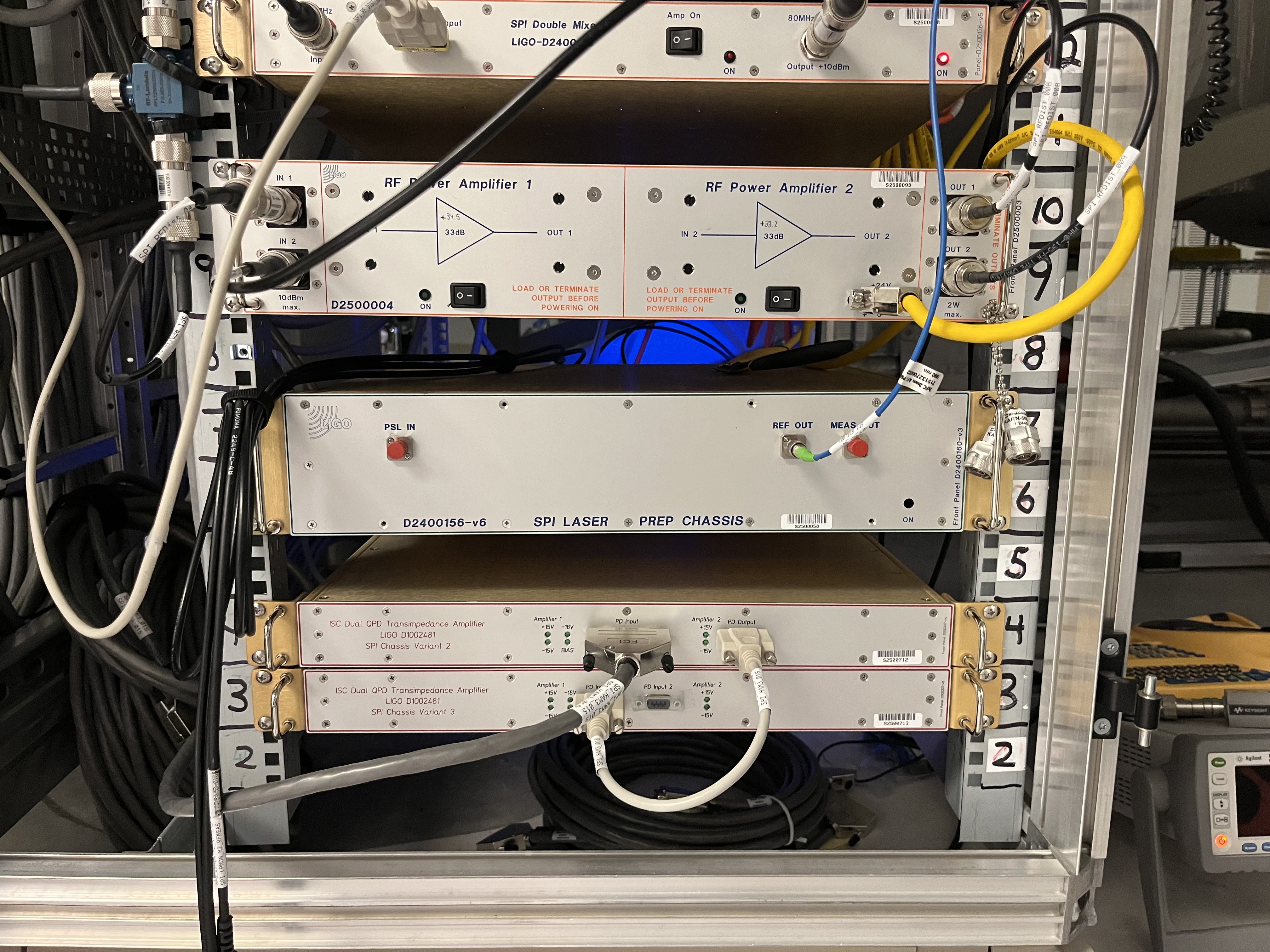
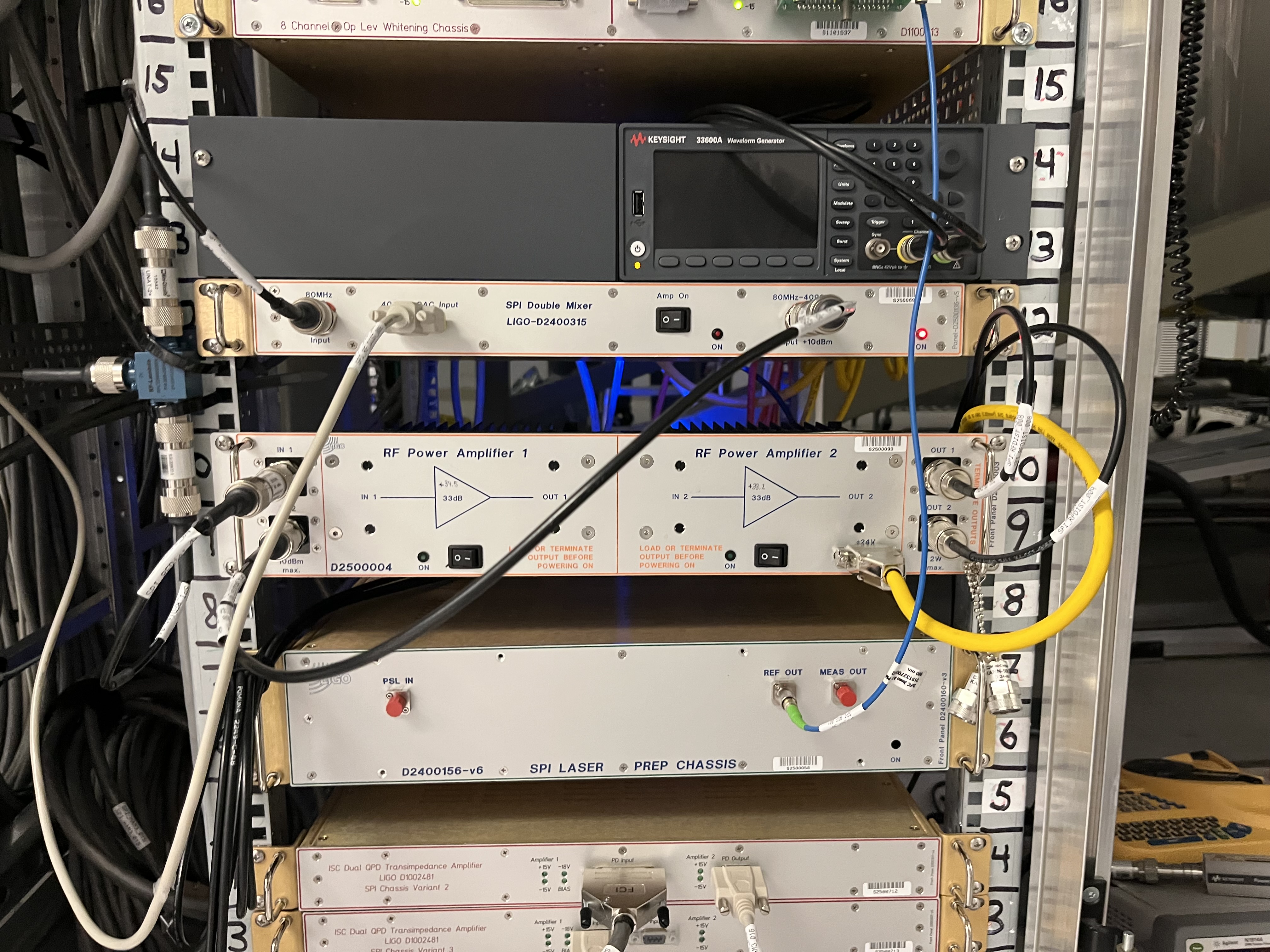
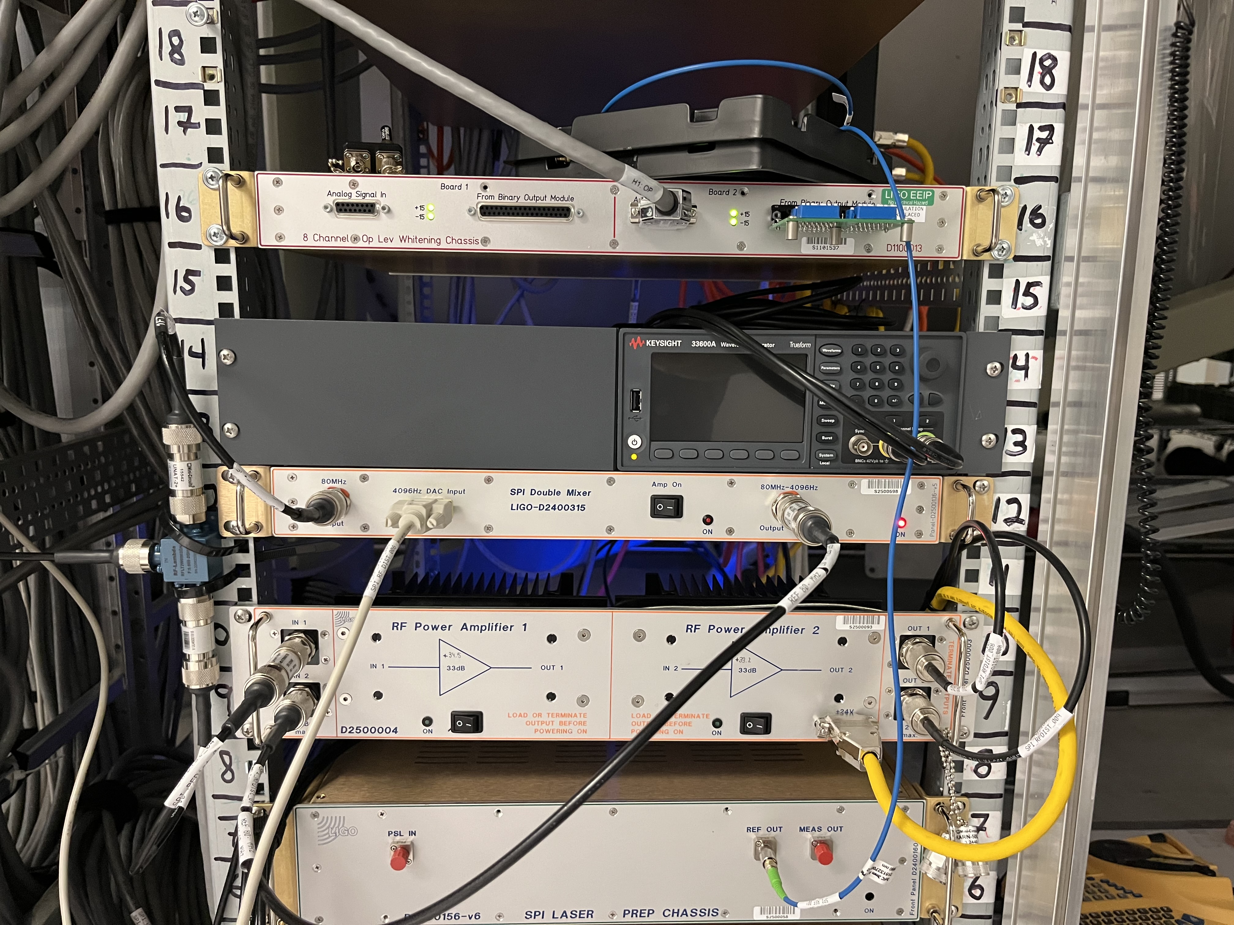
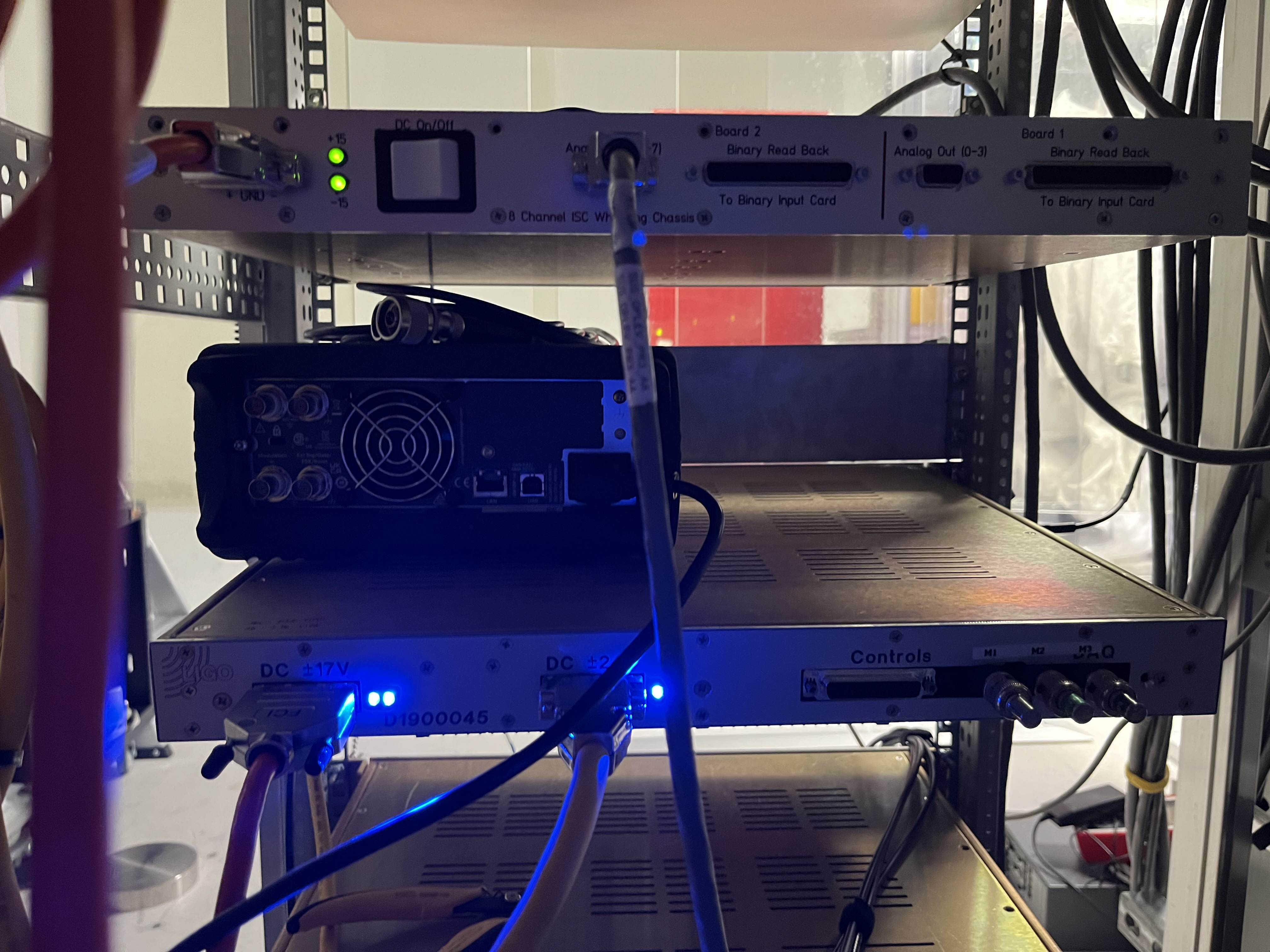
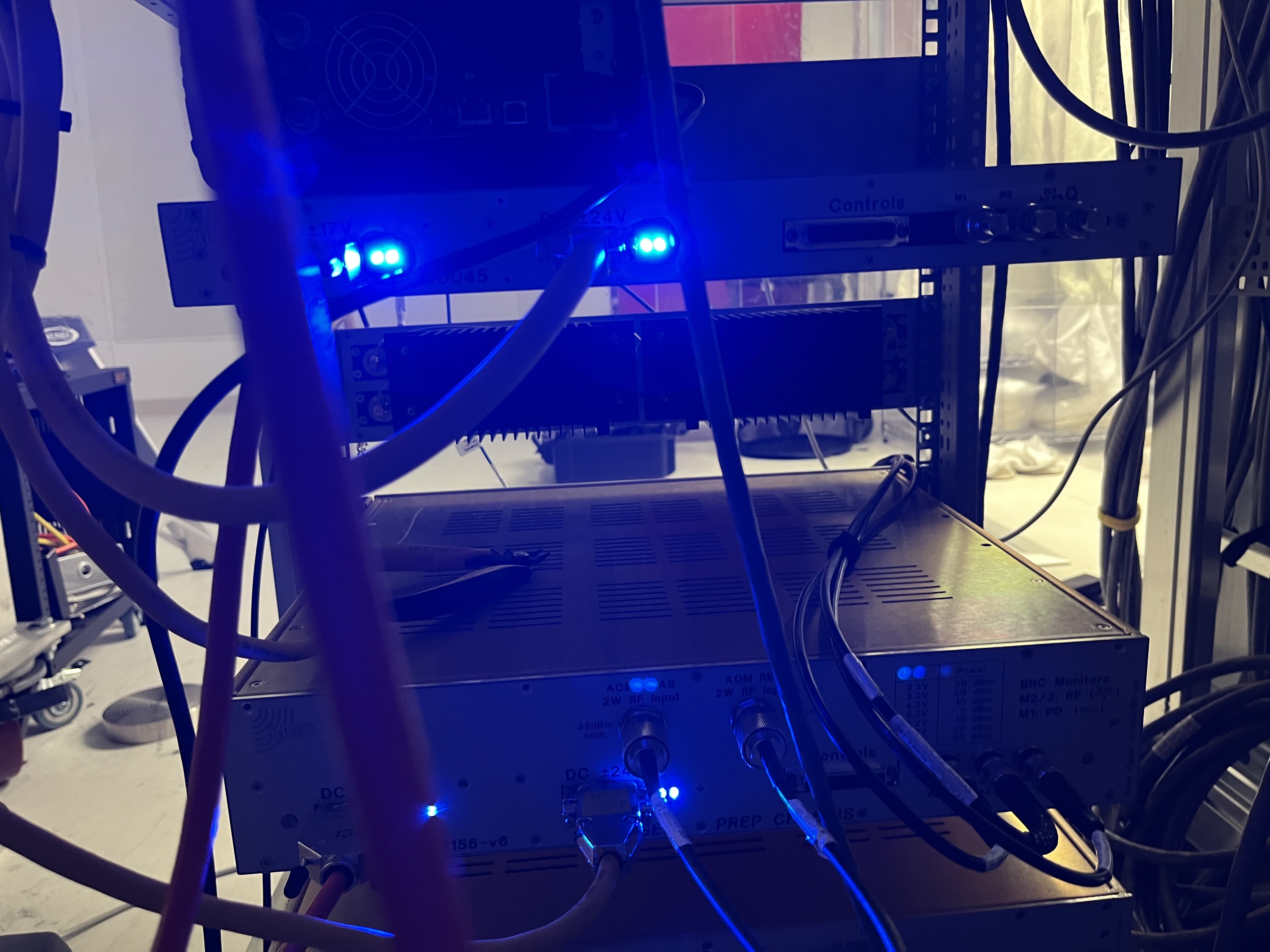
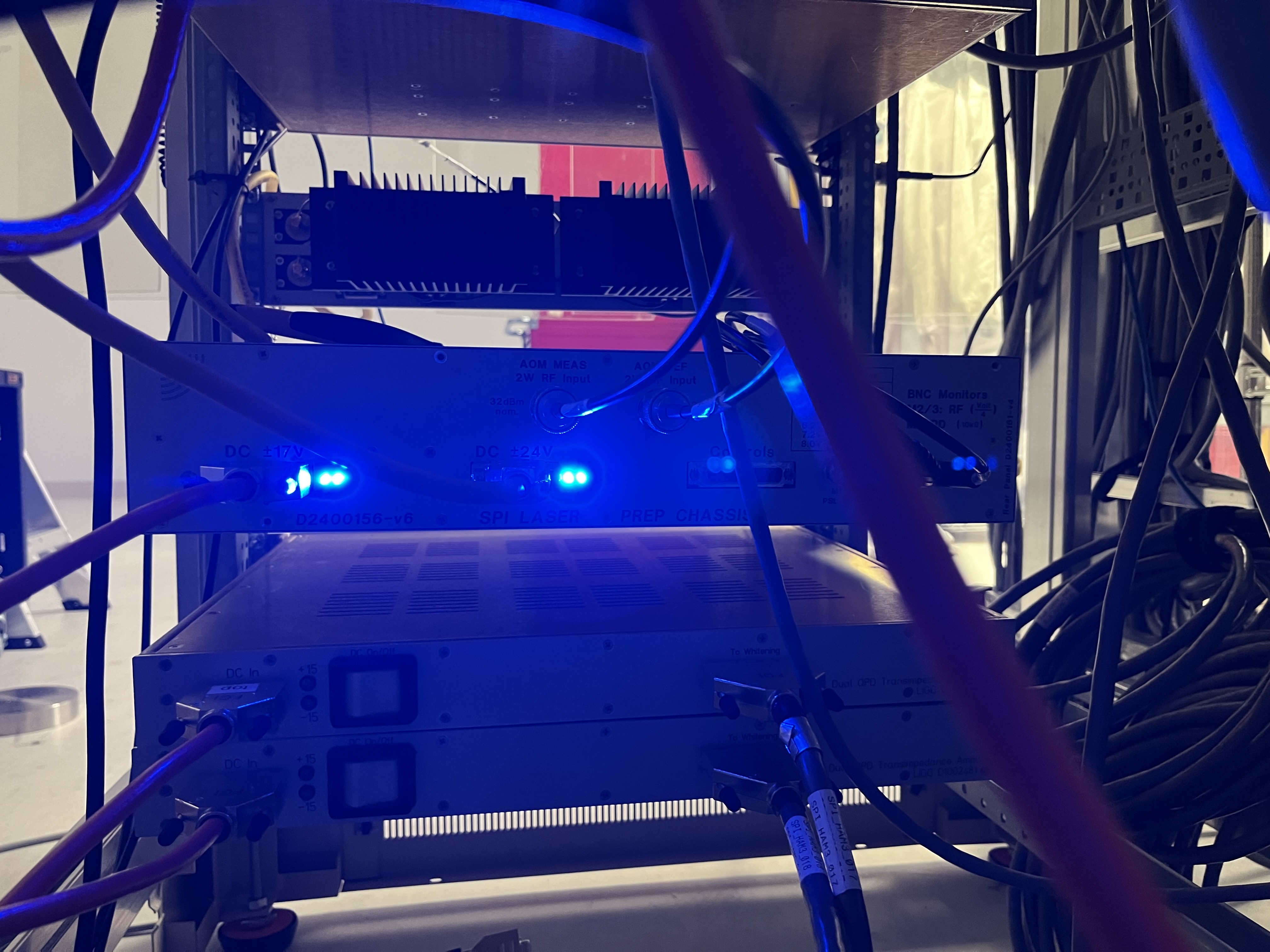
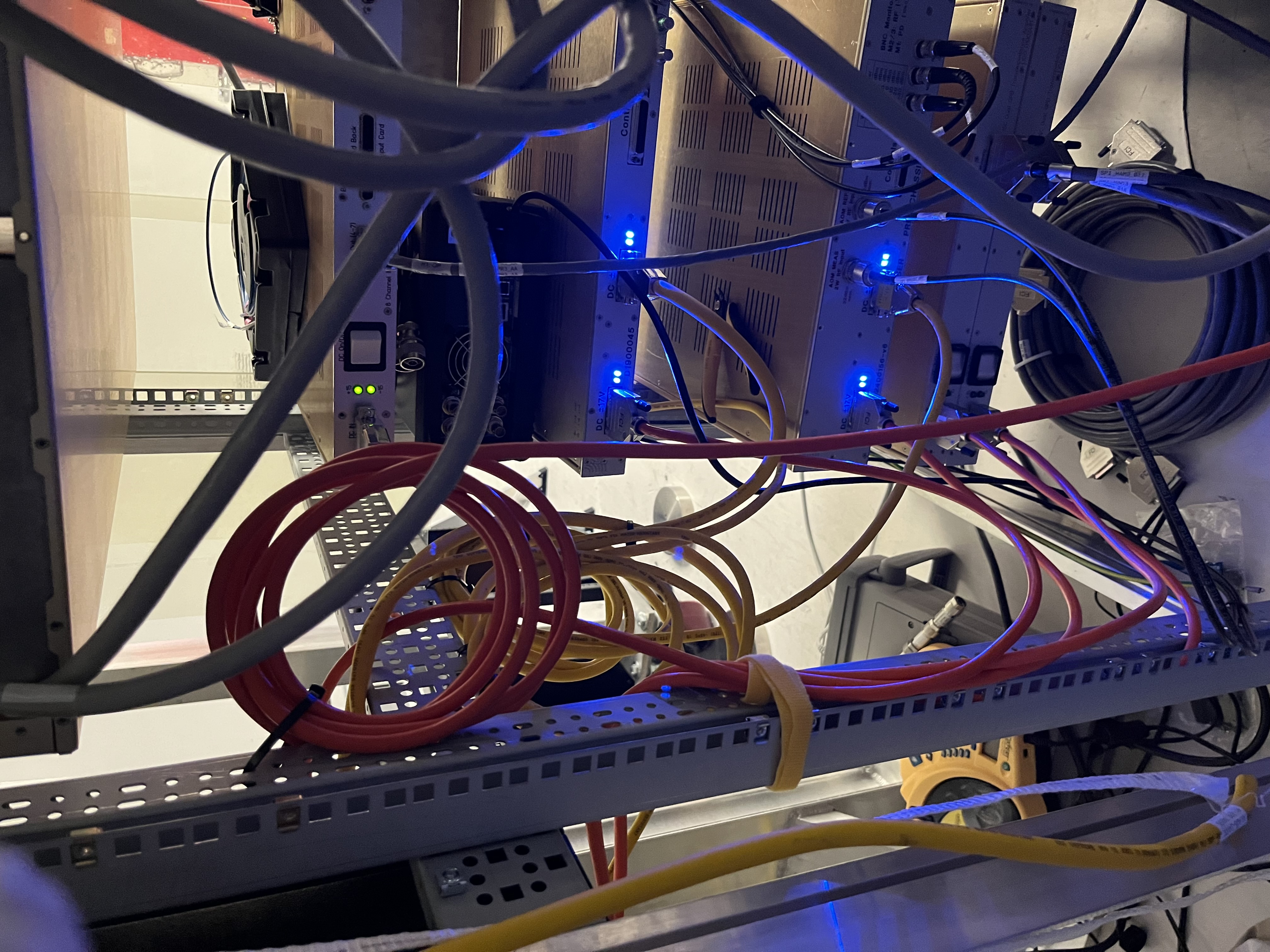
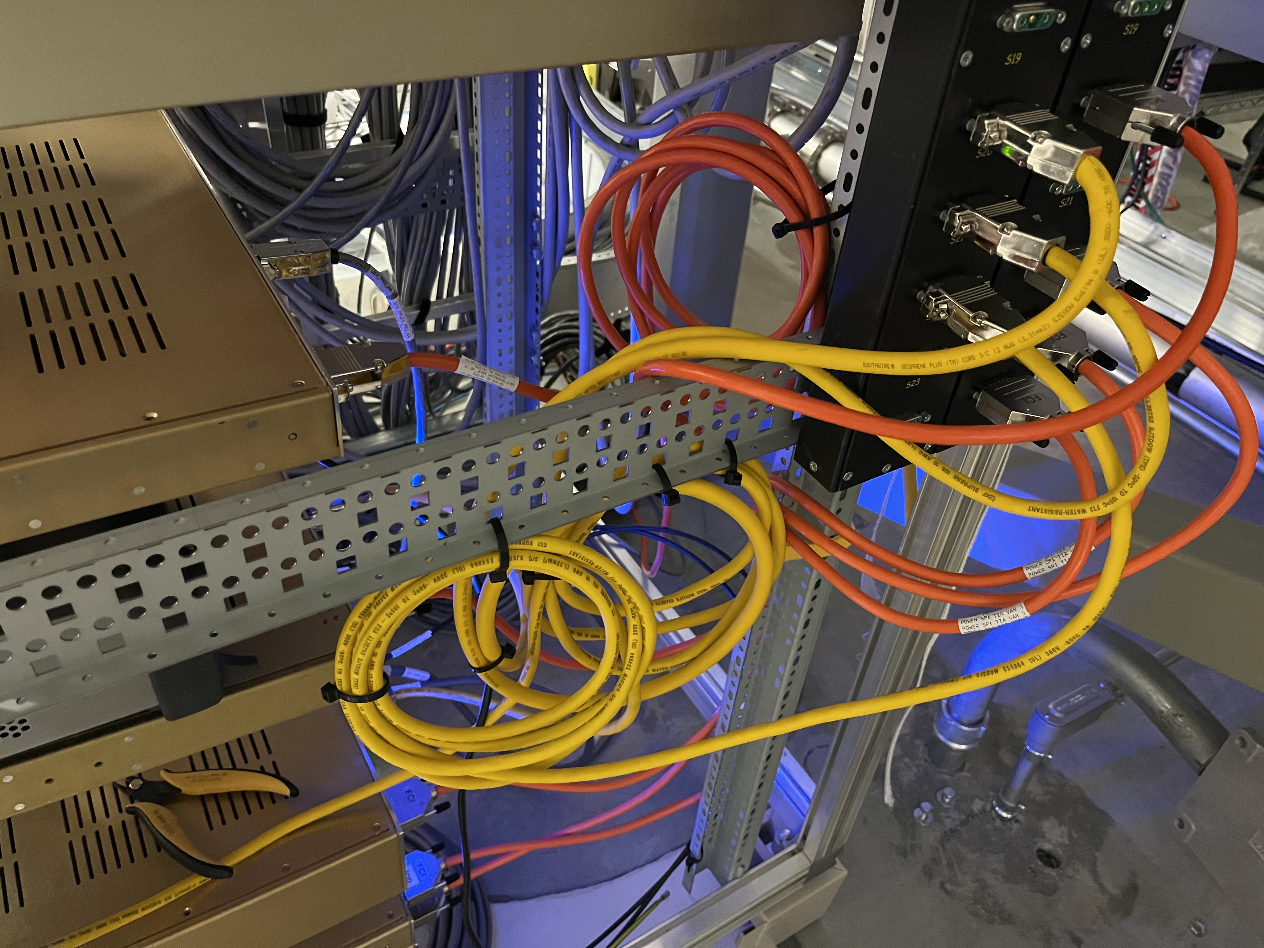
Wednesday we continued from 90352, We installed the full rack for SPI in SUS R2 and made all connection between different SUS R2 racks as well as connections from TIA to DAC. (Front:IMG_6377.jpeg)(Back:IMG_6388.jpeg). As well as, hooked up to all the required power supplies. Still missing some connections namely SUS R2 to chamber connections
The RF power measurement going out from the 2W amp to the SPI prep was measured to be 31.6 dBm for both outputs of the 2W amp (after the amp warmed up).
This was measured by using the on site power mon w/ small power probe (Exact make and model will be added later). The site has a large power probe (the HP 8484A) but from 89523 it was found to have some strange nonlinearities. As such, the small probe was prefered for this test. Since the probe only has a 20dBm max power limit, 2x 10dBm attenuators (UNAT-10a) were used to lower the power to be able to be measured. Of course the UNATs have a 33dBm limit so special care was used to make sure that limit was not reached. This set up was calibrated by using a 0dBm signal which the probe measured as 0.1dBm. attaching the 2 attenuators the same signal read -20.0dBm (a 20.1dB difference). Then I measured the 2 ports which read 11.8dBm for the Meas output and 11.7dBm for the Ref output. Once the amp warmed up (~20 minutes of waiting with it on) these values both fell to 11.5dBm. Adding back that 20.1dB, this leaves both port with the expected output of 31.6dBm. With an error of +/-0.1dBm.
This value is 0.4dBm lower than the optics lab measurement with the larger probe but is a more precise measurement with less error.
The SPI wiring diagram D2400111 is labeled wrong. Namely it says Output 2 of 2W amp connects to the meas port of SPI prep. And Out 1 of of 2W amp connects to the ref port of SPI prep. This is wrong. Out 1 of of 2W amp connects to the meas port of SPI prep (I physically labeled SPI_RFDist_008) and Out 2 of of 2W amp connects to the ref port of SPI prep (I physically labeled SPI_RFDist_009)
We also installed 3 BNC cables for the monitor channels of SPI Prep. These are not labeled in the wiring diagram but Jeff physically labeled them as SPI_LPMON_M1_PD, SPI_LPMON_M2_RFMEAS, and SPI_LPMON_M3_RFREF. Which monitor: the PD inside SPI prep, the RF power for the 80 MHz Meas signal, and the RF power for the 80- MHz Ref signal respectively.