[Begum, Camilla, Ryan S., Madi, Sheila]
Measurements taken on 2026-06-08 and 2026-06-09:
After the new OPO installation, beam profiles measured on HAM7 table (Sheila 90345) indicated that the OPO mode is different for the new OPO. This of course would both affect OMC mode matching as well as FC mode matching. The following measurements are beam q-parameter measurements measured on the FC path (green path in attached diagram), for beam upstream of ZM2 (p6,p7,p8,p11,p12) and downstream of ZM2 (p9,p10). The camera/profiler used is Phasics SID4 (MIT unit).
Phasics camera is capable of giving us a beam waist and how far away that waist is from the camera position (- upstream of cam, + downstream of cam), however the fidelity of these values are dependent on where the camera is placed with respect to the waist: if it is too close to the focal plane (where the beam divergence is small), or if the beam is too large for the sensor the extracted values don't make sense. So, we have measured at least two positions with known distance from each other evaluate the fidelity q parameters obtained.
Multiple measurements were taken at p10 point, varying ZM2 curvature. The strain gauge values are given in the table, 1.2 V and 6 V strain gauge correspond to 0 and 200 V pzt supply voltage to ZM2 psam. For points p6,7,8,9,10 the A:L2 lens was sitting in the "middle" position, both edges of the stage is lines up with its rail (will add photo here). Below table is from measurements taken on 06-08. The camera reports three numbers for each parameter, major, minor, radial. Major and minor do not necessarily line up with horizontal and vertical axes. The screenshots for each case report what the angle is. The .txt file for each data point also reports wx and wy for the near field beam, so we can potentially infer from there.
| Designation | 2w0(mm) | z(mm) | Δz(mm)(downstream ref. optic: +) | ref. optic | ZM2 Strain Gauge(V) |
| p6 | 0.616, 0.560, 0.588 | -156.5, -158.6, -157.6 | 65(distance to iris) + 240 (iris to ZM1) | ZM1 | 3.15 |
| p7 | 0.516, 0.549, 0.533 | -430.8, -449.2, -439.2 | 245 + 240 | ZM1 | 3.15 |
| p8 | 0.516, 0.530, 0.523 | -355.4, -359.1, -357.2 | 150 + 240 | ZM1 | 3.15 |
| p9 | 0.274, 0.298, 0.287 | -360.8, -366.4, -363.5 | -870 | ZM3 | 3.15 |
| p10 | 0.244, 0.247, 0.248 | -323.8, -335.3, -329.3 | -915 | ZM3 | 3.15 |
| p10 | 0.250, 0.219, 0.237 | -291, -283.3, -287.2 | -915 | ZM3 | 6 |
| p10 | 0.287, 0.285, 0.289 | -363.4, -350, -356.6 | -915 | ZM3 | 1.2 |
| p10 | 0.268, 0.250, 0.264 | -321.9, -306.5, -313.9 | -915 | ZM3 | 4.5 |
There are two readily available beam parameter tuning options we have for the FC path: the ZM2 curvature via psam, and the A:L2 lens via the translation stage it lives on. In the afternoon, we parked the Phasics camera on p11 and p12 positions (between p7 and p8) and recorded beam parameters for A:L2 lens on three positions (middle:0mm, -13mm: lens closer to ZM1 by 13mm, +17mm: lens further away from ZM1 by 17mm). Below table is from measurements taken on 06-09.
| Designation | 2w0(mm) | z(mm) | Δz(mm)(to ref. optic) | ref. optic | ZM2 Strain Gauge(V) | A:L2 position (mm) |
| p11 | 0.677, 0.684, 0.68 | -265.5, -259.2, -262.1 | 180+240 | ZM1 | 3.15 | 0 |
| p11 | 0.649, 0.685, 0.667 | -254.9, -250.9, -252.8 | 180+240 | ZM1 | 3.15 | -13 |
| p11 | 0.673, 0.749, 0.712 | -273.5, -269.7, -271.5 | 180+240 | ZM1 | 3.15 | +17 |
| p12 | 0.730, 0.649, 0.692 | -295.7, -308.7, -301.3 | 230+240 | ZM1 | 3.15 | 0 |
| p12 | 0.638, 0.723, 0.682 | -286.9, -277.3, -281.4 | 230+240 | ZM1 | 3.15 | -13 |
| p12 | 0.668, 0.725, 0.697 | -322.3, -314.2, -318.0 | 230+240 | ZM1 | 3.15 | +17 |
Raw data is in the attached .zip


E2100298 shows PZT supply voltage vs RoC for ZM2 (SN1).
Below is the table for ZM2 strain gauge (V), pzt supply voltage (V) and RoC (m) for relevant data points.
| Strain Gauge (V) | PZT Supply Voltage (V) | RoC (m) |
| 1.2 | 0 | 0.8211 |
| 6 | 200 | 0.8911 |
| 4.5 | 120 | 0.8724 |
| 3.15 | 90 | 0.8619 |
Phasics not reliable for accurate beam parameter estimation.
Some operational constraints of the Phasics camera: It needs to be placed at a location not too close to the waist, so that it can see enough divergence of the beam to estimate the beam parameters. And, the beam size cannot be too large compared to the sensor size.
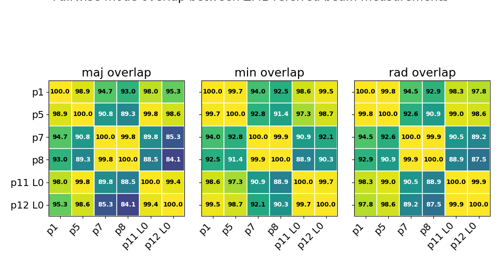
Based on these, it seemed reasonable to take multiple measurements for each beam we'd like to profile, then evaluate the consistency of these measurements. The attached matrix plot shows the intensity overlap integral x100 for beam parameters estimated at p{#} positions, for pairs of measurements. P1 and P5 were taken on the same day, P7 and P8 also belong to the same day, P11 and P12 on the same day. They are all points downstream of ZM1, upstream of ZM2.
Diagonal elements show data points taken in the same day, are consistent with each other. However, data taken on different days are not mutually consistent. This points to a fatal flaw in operating the Phasics camera this way. For fun, attached is a second plot that shows Gaussian beam propagation implied by each measurement. The "target" and O4 values for the beam parameter were taken from Keita's log 59515.
We need to take accurate measurements on the ZM1 --> ZM2 --> ZM3 --> FC1 path, with a different beam profiler.

This inconsistency between measurements taken on different days may not be a measurement device failure.
I flagged some spatial dependence to PSAM RoC with the new OMA2/OMA3 PSAMs in recent beam profiles in HAM6 at LLO: LLO81923.