J. Oberling, R. Crouch
Here is the final position of the BBS optic in the LHO Global coordinate system, based on our final FARO measurements taken on 6/29/2026.
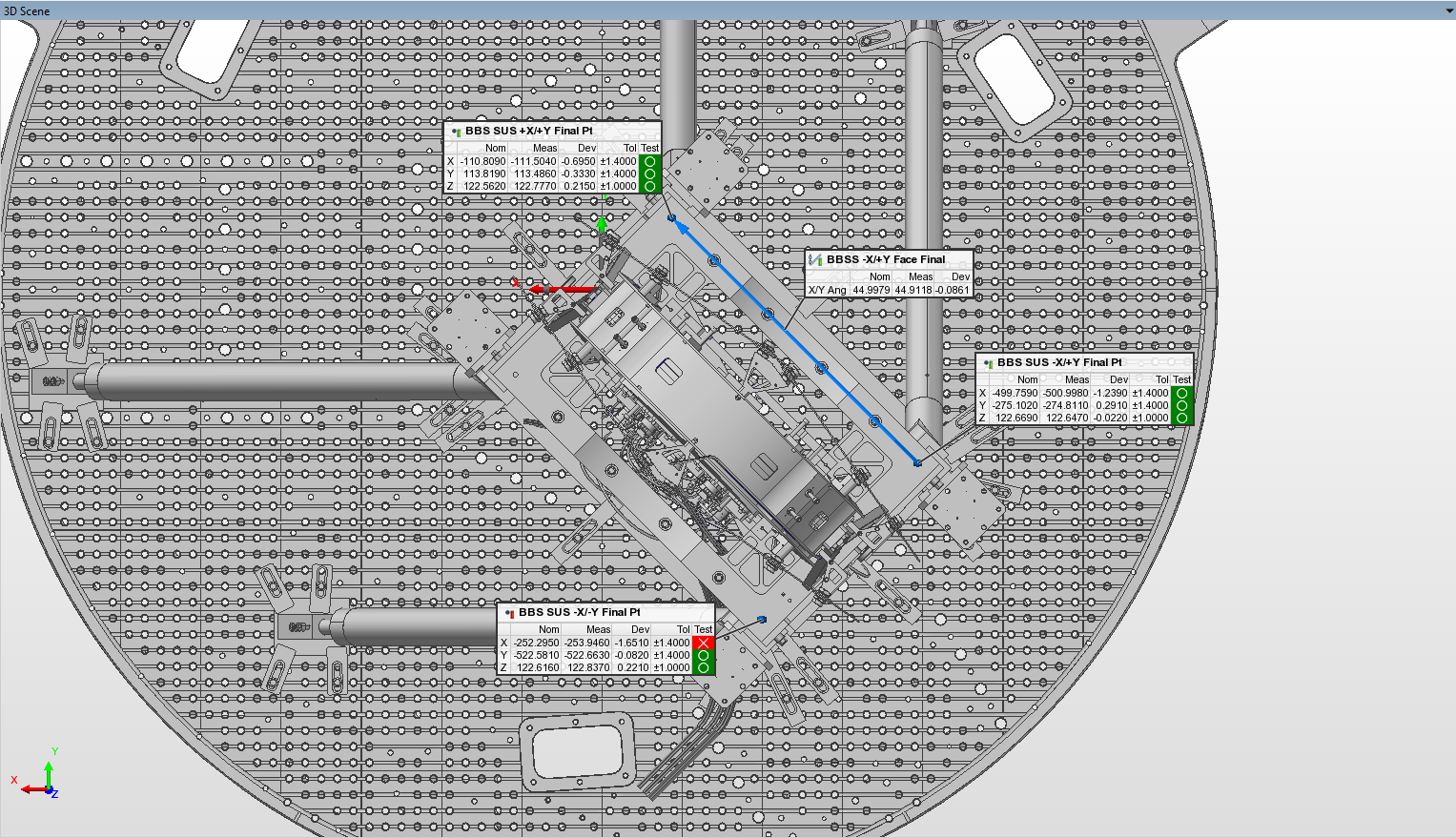
The first attachment shows the deviations of our measurement points on the BBSS from CAD nominal and the line shows the measured yaw of the BBSS cage. The listed "X/Y Ang" is the X/Y projection angle of this line; the line is projected to the X/Y plane and the angle to this projection is measured from the +X axis. In other words, this is pure yaw, and any contribution from an angle w.r.t. the Z axis has been removed1. As can be seen, we had to yaw the BBSS CW much more than expected based on the Zemax model of the IFO. Recall, the yaw angle was set by Betsy and Keita using both the PSL and SQZ beams (final yaw alignment before our FARO measurement is in alog 90759 and the final check before closing out the chamber is in alog 90920). We had started by setting the BBSS yaw close to CAD nominal (we were under 100 µrad), but when the check was done with PSL and SQZ beams a futher 2.5 mrad of CW yaw was estimated as necessary to align both beams. We ended up using HEPI to add ~1.3 mrad of CW yaw, which was deemed good enough. Why was this necessary? We have no way to measure the optic pitch and yaw in-chamber (only way to do so is to remove the spool piece between HAM3 and BSC2 and set up a total station/LAC combo in a spot that is normal to the optic face using the FARO; we were told removing this spool piece was not an option), so I'm not sure but I can make a couple guesses. I think it's likely a combination of at least two things: The yaw alignment from the test stand doesn't survive being craned into the chamber and our as-built input and output optics (PRC and SRC optics) placement/pointing is such that the BBS pointing needs to be changed from the Zemax nominal. Regarding the former, we know that the test stand pitch alignment doesn't survive, as I looked back through my old aLIGO install notes and we never had a pitch alignment survive being craned; the smallest move I found was ~500 µrad, and I found a couple that were between 2 - 3 mrad, so having to add a mrad or two is not unheard of. For the latter, I would like to measure the monuments we used to do the in-chamber alignments during aLIGO installation with the FARO. We did this for the test stand monuments we did all of our Corner Station cartridge alignments on (see these 2 pictures from my BS pre-disassembly test stand measurement mega-alog), and found them to not be where we thought they were; I have a suspicion that we'll find similar with our in-chamber alignment monuments.
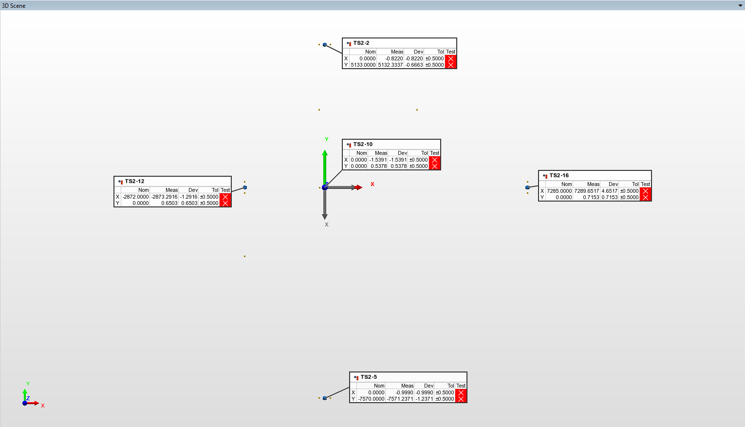

But, this is not the BBSS position and yaw deviation we had when we aligned the BBS optic to the ISI on the test stand (BBSS test stand position and yaw alignment is in alog 90274). Our goal was to place the BBSS in-chamber as close as we could to the deviation we had on the test stand, so that the BBS optic itself was better positioned in the LHO Global coordinate system (since the BBS was aligned to nominal with the SUS cage at the test stand deviation). To more easily assess how well we did in that, and to help in calculating the BBS optic position, I replaced the Nominal column with our Measured data from the test stand alignment; this is shown in the 2nd attachment (the Measured column is the same between the 2 attachments, it's the Nominal column that changed). As a reminder, our final test stand position deviations are given in alog 90363.
To calculate the BBS in-chamber position, I averaged the measured deviations from the Test Stand Nominal attachment (X = -1.2mm; Y = 0.0 mm; Z = +0.1 mm; rounded to the nearest 0.1 mm to match our measured BBS test stand deviations) and then added our measured optic deviation from the test stand alignment (X = +0.3 mm; Y = +0.3 mm; Z = -0.1 mm). These deviations were then used to calculate the BBS optic position; the results are shown in the table below (all units are in mm).
| Axis | Nominal | Measured | Deviation | Tolerance |
| X | -202.6 | -203.5 | -0.9 | +/- 1.4 |
| Y | -184.1 | -183.8 | +0.3 | +/- 1.4 |
| Z | -83.1 | -83.1 | 0.0 | +/- 1.0 |
1: PolyWorks measures angles directly to the feature in a 3D space, so using its direct angle measurements such as spatial angle (angle measured from the positive axis direction directly to the feature) and acute spatial angle (angle measured from the closest axis direction, so either positive or negative, directly to the feature) can sometimes cause some confusion when trying to assess pitch/yaw/roll angle. Using yaw as an example, the issue arises when the feature begins to approach either the positive or negative Z axes. Imagine a line with a small angle w.r.t. the X axis (so a small yaw angle) but a large angle w.r.t. the X/Y plane (or small angle w.r.t. the Z axis). In this case, the spatial angle in PolyWorks would measure a large X Angle, since it measures directly to the feature, even though the yaw angle is actually small. This is where the projection angles come in, although the user must be careful in their application. PolyWorks has 3 available projection angles to calculate for a direction-based feature: X/Y Angle, Y/Z Angle, and Z/X Angle. For each of these, the direction of the feature is projected onto the plane indicated (X/Y -> X/Y plane; Y/Z -> Y/Z Plane; Z/X -> Z/X plane) and the angle is then measured from the first listed axis to this projection (so the Z/X projection angle is measured from the +Z axis, Y/Z projection angle measured from the +Y axis, etc.). From my testing so far the X/Y Angle can be used to measure yaw in every circumstance I've tried it, but one must be careful with the Y/Z and Z/X projection angles. These can be useful to measure pitch and roll, but measurement features must be set up to take advantage of this (i.e. you don't want to use a feature that lies primarily along the X axis to measure the Y/Z projection angle, as the data will almost certainly be meaningless).