IMC Fast path looks good.
I and Elenna went to the floor and measured the OLTF of the IMC loop, injecting into the IMC CM board. UGF was 43.2kHz with 54deg phase margin, a bit high in frequency but not crazy high, and the TF shape was good in amplitude as well as phase. See PXL_20260720_192425851MP.jpg.
FYI the UGF was 38.5kHz back in March 09 2026 (alog 89438).
M3 stage acquire ON/OFF switching question.
We have noticed that the TF from M3 coil input (or drvalign_L2L_OUT) to VOLTMON and FASTIMON changes as Acqire ON/OFF changes. Is this supposed to be the case? And none of these TFs are flat. Is this supposed to be the case?
MC2-MC3-M3_BIO_TF.png shows the TF from M3 DRIVEALIGN_L2L_OUT to FASTIMON for MC2 and MC3 in various BIO states. State 1 (Acq Off, LP Off) and state 3 (Acq Off, LP On, this is our nominal state) give the same TF, which is different from state 2 (Acq On, LP Off) and state 4 (Acq On, LP On). We can say that LP On/Off is properly compensated for in digital but I'm not sure if this means that Acq On/Off is not switching in analog, because I don't know how the IMON in implemented.
Caveats: For MC2 all four states were tested. For MC3 only state 2 and 3 were measured. MC2 and MC3 are consistent with each other. TFs are only plotted for LL because all coils look similar.
FYI, on Friday we have tested to acquire in all four of M3 BIO states and never successfully locked IMC with nominal M3 gain for any state. Even if acquire ON/OFF is stuck to one state in analog (which I'm not sure if that's the case), it's not the only problem.
Today I tested locking with state 2, it didn't lock with nominal gain but it locked with the same reduced gain setting we've been using since Friday (ISCINF_L_GAIN=0.035, DRIVEALIGN_L2L_GAIN=0.2). I switched the state back to state 3 after that.
M3 stage comparison with MC1 and MC3
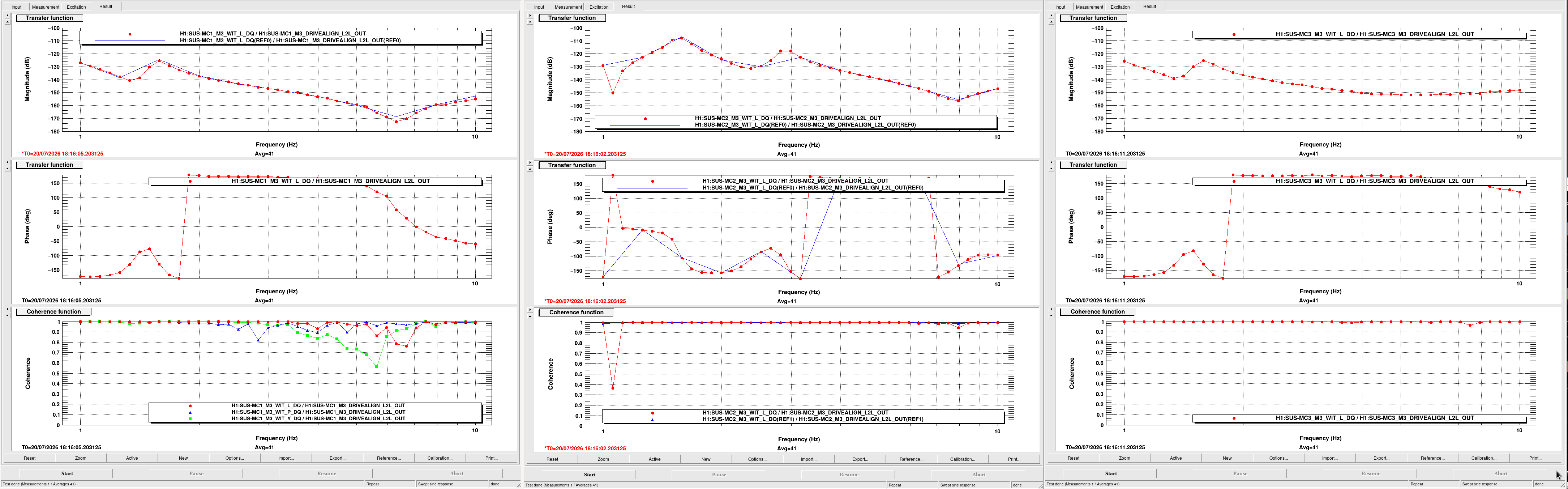
Screenshot_2026-07-20_11-51-08.png shows the M3 stage DRIVEALIGN_L2L_OUT to M3 witness L transfer function for MC1, MC2 and MC3 from left to right. They all look different but MC2 shows an extra bump at 3Hz.
Other observations
IMC sometimes locks without M3 stage feedback, but fails much more often than with M3 stage feedback, seemingly due to larger kick to the FSS.
Once IMC locks, you can easily switch between the following gains. Both seem to be very stable:
| M3 DRIVEALIGN_L2L_GAIN | M3 ISCINF_L_GAIN | |
| M1 and M2 reduced, M3 reduced further | 0.2 | 0.035 |
| M1 and M2 full, M3 disabled. | 0 (ramp down first) | 1 |
I never successfully transitioned to "all full" actuation (i.e. M3 DRIVEALIGN_L2L_GAIN=1 and M3 ISCINF_L_GAIN=1) nor M3 reduced by 0.2 and M1 M2 full (i.e. M3 DRIVEALIGN_L2L_GAIN=0.2 and M3 ISCINF_L_GAIN=1).


Jeff K, Sheila-
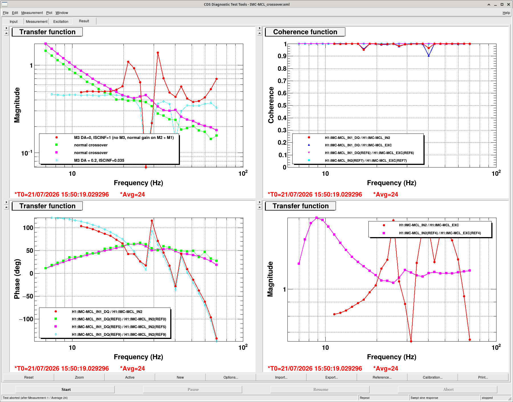
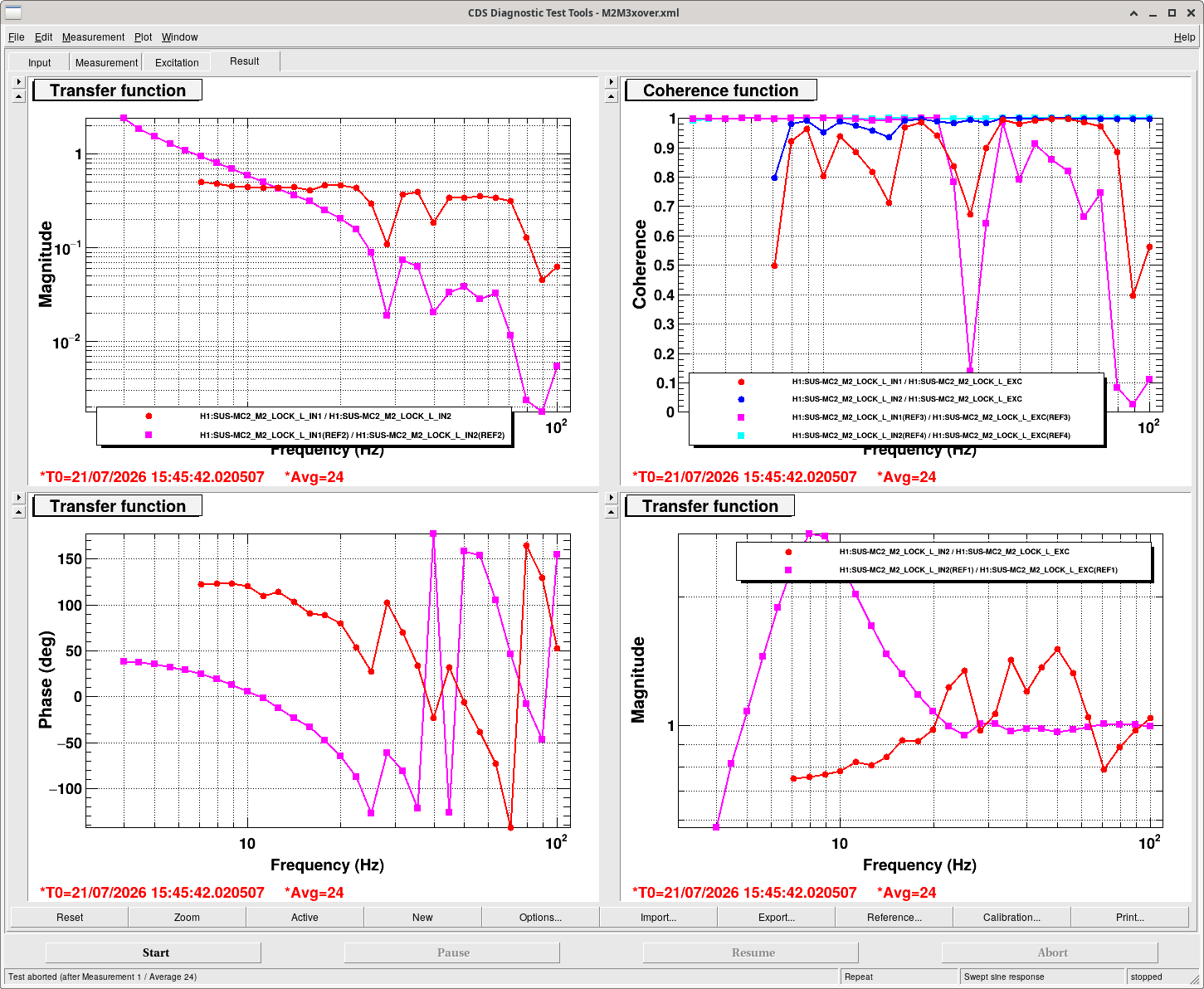
The blue trace in the first sreenshot is with the reduced ISCINF and M3 drivealign gain that Keita describes above, this is a measurement of MCL crossover, which should be (M1+M2+M3)/fast gain.
The red trace in the second screenshot is taken in the same state, with the excitation in M2 lock, which should measure (M1+M2)/(M3+F). These two measurements look the same, which would indicate that the M3 gain is low.
We also repeated the IMC_L measurement with the M3 gain set to 0 and ISC_INF at its normal gain, shown in the first attachement.