J. Kissel,

Executive Summary
We're continuing to debug issues seen with the IMC locking. One question that came up was whether we *can* confirm that all binary IO switching of the H1SUSMC2 M3 stage coil driver -- an *unmodified* Triple Acquisition Driver (see D0901047-v4) -- using the transfer functions between DAC output and the FASTIMON coil driver monitor circuits. And the real question they *want* answered is "is the BIO on the H1SUSMC2 M3 stage functioning normally, or is that broken and that's what's causing the issues with the IMC?"

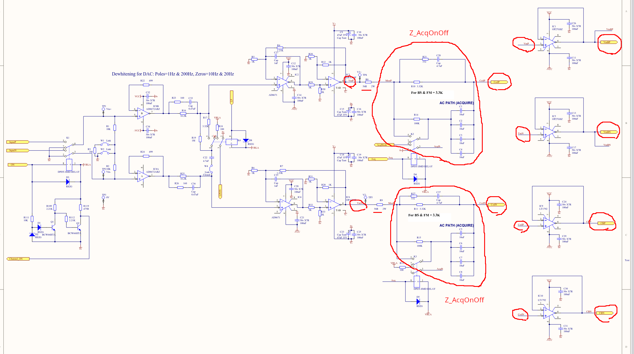
The short answer: NO, one cannot confirm the ACQUIRE switching with confidence with any of these coil driver monitor circuits. The TACQ driver is one of those drivers where the monitor pick-offs span a complex switchable output impedance network rather than a simple resistor. As such, neither VMON or the FASTIMON can measure the response of that switchable output impedance network, since you're monitoring the voltage across it. Elenna's TF posted to LHO:91155, which has the TACQ driver frequency response correctly compensated, also shows that at least the analog state matches the digital compensation state.

BUT -- I'm 95% confident that both LP and ACQ filters the H1SUSMC2 BIO switching are working normally, and switching the analog coil driver state. This is based on some weak coil driver monitor transfer function evidence, looking at the BIO monitor readbacks for the M3 Stage, and two decades of experience looking at the function of these things.

DETAILS

Attached is the simplest cleanest demonstration of the *lack* of visibility of the Acquire Filter:
    - Excite the transfer function from the DRIVEALIGN L2L filter bank, so you can send excitation to all four coils at once. Make sure there's no filters on, and the gain is set to 1.0.
    - Change the M3 EUL2OSEM matrix to have the L to UL, LL, UR, LR coefficients from 0.25 to 1.0.
    - Use the 'secret' state feature of the binary IO control, to switch the coil driver state to negative; i.e. State 1 = -1, State 2 = -2, State 3 = -3, and State 4 = -4.
    - This allows you to Turn OFF all coil driver frequency response compensation filters. Do so, turn them off, so that you're actually exposing the what frequency response of the coil driver you can measure.
Templates of the excitations can be found in
    /ligo/svncommon/SusSVN/sus/trunk/HSTS/H1/MC2/SAGM3/Data/
        2026-07-21_H1SUSMC2_M3_L_to_FASTIMON_NoCompensation_tfs.xml
        2026-07-21_H1SUSMC2_M3_L_to_VOLTMON_NoCompensation_tfs.xml

One can see in this "clean" version of the fast-imon TF 1st attachment. One only really sees the response change when the low-pass filter is turned ON vs. OFF. One might argue that there *is* a little change between STATE 1 and STATE2 (turning the Acquire filter ON, bypassing R14), but this is dirt coupling; we expect the zero:pole response to change from (9:82) Hz pair to a (1:46) Hz pair.

My justification that "it's a real change, even though it's dirty," and that the FASTIMON does show that the switch is working -- if I take the same transfer function to the voltmon circuit, 2nd Attachment (which measures the voltage across a single resistor, but *upstream* of the acquire network), one sees no change at all between STATE1 and STATE2. Said differently -- because we *do* see a change in the FASTIMON TF between STATE 1 and STATE 2, albeit not the real TF change which we know we shouldn't be able to see, but still -- a change -- is weak proof that the acquire filter is changing, and the BIO is functional.

Remember:
 - From LLO:4495, for an unmodified TACQ Driver, we expect the poles and zeros to be changing as follows:
        State         Switch State                       Freq. Resp            DC Transconductance
                       ACQ  |  LP                          (z):(p) [Hz]             [mA/V]
        STATE 1        OFF  |  OFF                         (9):(82)                   0.33
        STATE 2        ON   |  OFF                      (1.05):(46)                    |
        STATE 3        OFF  |  ON                    (9 11 21):(1 82 210)              |
        STATE 4        ON   |  ON                 (1.05 11 21):(1 46 210)              V

 - For bode plots of the frequency response of all these TACQ driver states, and the difference between a *unmodified* vs. *modified* TACQ driver see L1200226.

 - For an info-graphical representation of the state of the digital compensation w.r.t. the analog filter state, see StateMachineDiagrams_TripAcqDriver-v7.pdf from T1100507.

 - In general, none of the SUS coil driver circuit drawings, nor the SUS coil driver monitor circuit drawings show the complete monitor circuit, so it's difficult at best to parse the total circuit system to understand the calibration. Instead, go to CoilDriverMonitorMath_CurrentMonitor.pdf posted as an other file to D070480-v2 for a complete picture of the monitor system, from which you can derive the math. I summarize it here:
   From the second page of that math, you can see that the transfer function between the Fast IMON circuit output voltage, V_IMON can be calibrated into current across the coil, I_coil by the following transfer function:
       V_IMON                 R25         2
      -------- =  2 * Z_out * ---      = --- * Z_out
       I_coil                 R24         3
where,
     . as part of the design principle, R25 = R35, and R24 = R27 = R29 = R33, and for the D070480-v2 circuit, R25 = 10e3 [Ohm] and R24 = 30e3 [Ohm], hence, R1/R2 = 1/3, and
     . Z_out, in the case of the TACQ driver is the entire complex switchable impedance network.

 - The list of HSTS with modified vs. unmodified TACQ drivers on their lower stages: LHO:32021

 - There *are* modified "narrow-band" coil driver monitor circuits out there, but they're only in PRM M2 and M3, and PR3 M3; LHO:72837


There seems to be no reason that FAST_IMON TF doesn't change in your measurement when acq mode is switched ON/OFF if FAST_IMON is just CBP-CBN scaled with a real factor in https://dcc.ligo.org/DocDB/0002/D0901047/004/Triple%20Acquisition.pdf. Is it?
Coil_current = (CBP-CBN)/Z_coil = (VmBP-VmBN)/(Z_coil+2*56+2*Z_AcqOnOff)
therefore
CBP-CBN = (VmBP-VmBN)*Z_COIL/(Z_coil+2*56+2*Z_AcqOnOff)
where Z_coil is the impedance of the coil and the cable combined, 2*56 is the resistance of R8 and R9 combined and 2*Z_AcqOnOff represents the impedance of the RC network used for Acq ON or OFF combined (there's one Z_AcqOnOff in the CBP path and another in the CBN path).
When you switch the LPF on or off, VmBP-VmBN changes.
When you switch the Acquire mode on or off, Z_AcqOnOff changes.
Either way, if CBP-CBN is used as FAST_IMON, TF from drivealign L2L to FAST_IMON (measured when all digital compensation filters are off) should change according to acq on/off as well as LPF on/off change.