jeffrey.kissel@LIGO.ORG - posted 11:44, Thursday 23 July 2026 - last comment - 12:21, Thursday 23 July 2026(91210)
Calibrating the SPI Optical Levers in to ISI Rotation (Modeled Version); QPD A -- (ISIHAM3 PIT / QPDA Normalized Spot Position) = 209.6e-6 [rad/rad]
J. Kissel

As it stands now, QPDA on ISI HAM2's ISIJ reflector is measuring the rotation of the ISI HAM3. The channels H1:SPI-H23_OL_QPD_A_{PIT,YAW}_OUT_DQ are still in "normalized position of the beam, s" [V/V = "radians"], as SEG1, SEG2, SEG3, and SEG4 have been converted from ADC counts to ADC volts with the transimpedance whitening stage compensated (see LHO:91157), and the PIT (lower - upper) and YAW (left - right) in [V] are divided by the SUM in [V].

Executive Summary:

Modeling the PITCH calibration of QPDA's normalized spot position, s, into ISIHAM3 rotation angular displacement, \alpha, yields 209.6e-6 [rad/rad], excellently similar to Arnaud's measured 240e-6 [rad/rad] from 91194.

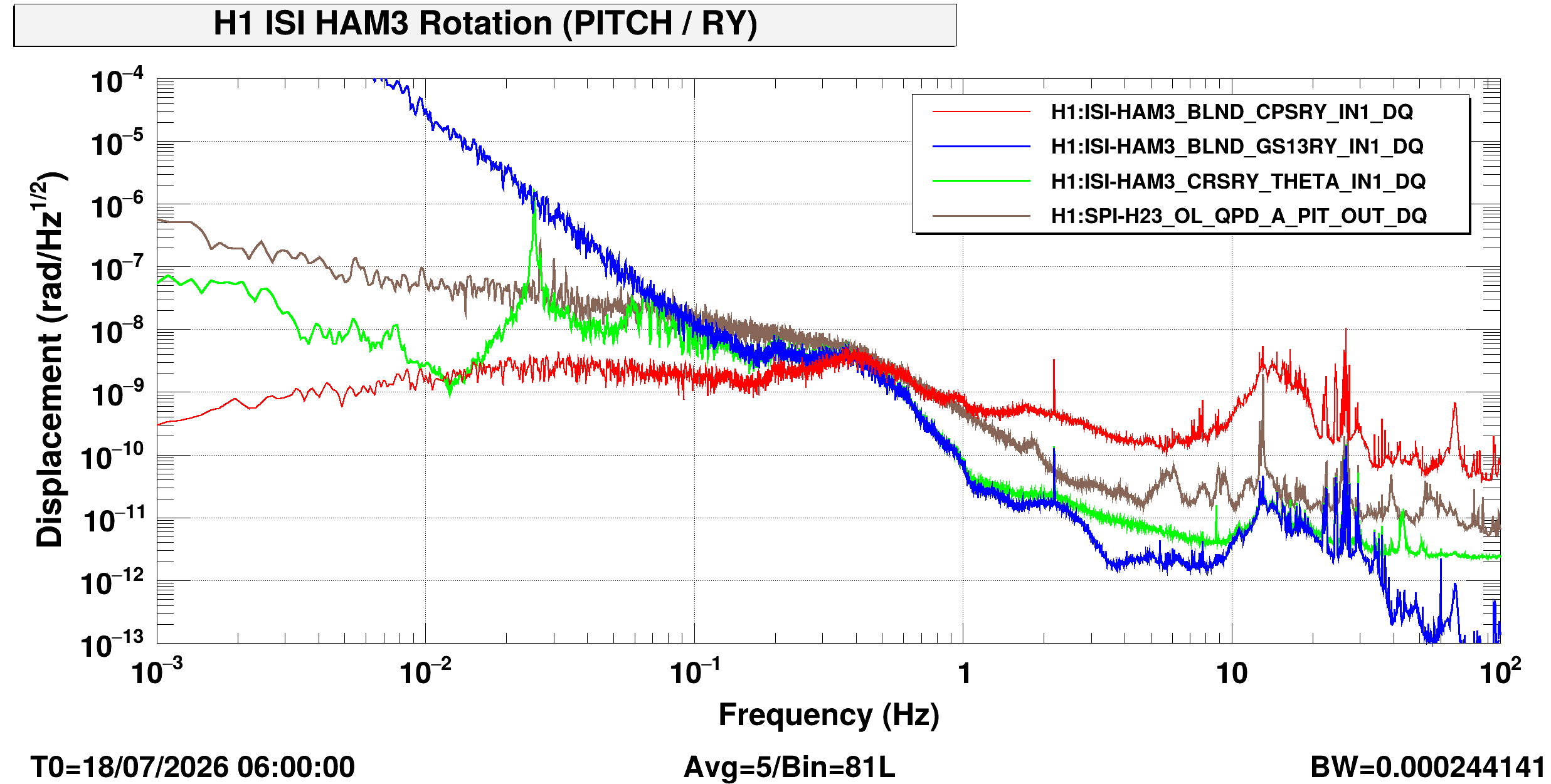
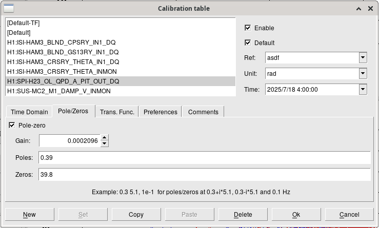
Thanks to Arnaud's excellent sharing/bookkeeping, I opened his template, and updated the calibration and post the plot again here. I also attach the updated calibration window parameters for the SPI channel, in the updated template which has been committed to
    /ligo/svncommon/SeiSVN/seismic/HAM-ISI/H1/HAM3/CRS/Templates/dtt/2026-07-18_0600UTC_H1ISIHAM3_CRSvsSPIvsISI_PIT_ASD.xml
(Note to future users, the QPD's whitening compensation is *included* in the calibration of this template because 2026-07-18 06:00UTC was before I turned on the front-end compensation for it on 2026-07-23 LHO:91157. So if you measure the ISI *after* 2026-07-23, then you don't need the (z:p) = (39.8:0.039) [Hz] zero-pole compensation in the DTT calibration. Also beware - after this aLOG I'm going to install the [rad/rad] calibration into the front-end too.)

This doesn't change the answer much (see updated plot below): the H1SPIH23 optical lever measure of ISI HAM3 PITCH is dominated by ADC noise up the 1-10 Hz region, as (sadly) expected from the SPI final design; see Figure Figure 1biii.2 of T2400145. This is because the beam spot is so large at HAM2 QPDA, and *that's* because we didn't have room on the HAM3 ISIK transceiver to include a beam reducing telescope that would decrease the spot size at ~15.5 [m] away.

The model, math, and calculation:

Sign conventions -- assume QPDA "+x" is -Y IFO coordinates and +YAW = +RZ of ISIHAM3, and QPDA "+y" is + Z IFO coordinates, and +PIT = +RY of ISIHAM3.

Thru integrating the power of the Gaussian beam at the QPD, P_y(x,y), from -infinity (the -y, i.e. -Z edge of the QPD) to the top / bottom (i.e. that between S1+S2 and S3+S4) boundary, one gets

                       / +inf   / y        2 P_{0}       w_{0}^{2}        2 (x^{2} + y^{2})
    P_y^{lower}(x,y) = |        |       --------------   ---------  exp( ------------------ ) dx dy
                       / -inf   / -inf   pi w_{0}^{2}      w^{2}                w^{2}

                              pi      2 P_{0}    / y               y^2
                     = sqrt( ---- )  ----------  |       exp( - 2 -----) dy
                               2      pi w^{2}   / -inf            w^2

                         P_{0}                     y
    P_y^{lower}(x,y) =   ----- (1 + erf ( sqrt(2) --- ) )
                           2                       w

with y being the spot position of the beam, with power, P_{0}, and radius, w, at the detector. erf is the well-defined Gaussian Error Function. Assuming the beam is centered on the QPD, that means the power on the top and bottom halves are equal, and thus s_pit as
              P_y^{lower} - P_y^{upper}
    s_{pit} = ---------------------
                       P_{0}

                          y
    s_{pit} = erf( sqrt(2) ---  )
                          w

                 erf(z) ~ 2 z / sqrt(pi)

              2 sqrt(2)  y
    s_{pit} = --------  ---
              sqrt(pi)   w

Importantly, s is a dimensionless quantity. Regardless of whether the QPD segments are (a) uncalibrated, (b) calibrated into ADC volts proportional to photocurrent, or (b) calibrated into milliWatts of incident power, if you create a creating PIT and YAW signal, that's normalized by the SUM in the same units, then you *always* gets you the "right" normalized spot position units. Some folks are even so bold as to refer to the QPDs as "self-calibrating" because of this.

But there's more to calibrating the QPD if you want to interpret the normalized spot position as an angle from somewhere. We do so by first solving for the spot displacement at the QPD, y, (converting 2 sqrt(2) = sqrt(8) along the way)

              pi
    y = sqrt( --- )  w  s_{pit}
               8

and then assume a very scalene right-triangle and the small-angle approximation convert the beam displacement to +\theta_PIT = +RY in [radians]. That process ends with "just" dividing by the "lever arm," L_{OL} distance between the HAM3 ISI center of rotation and the QPDA's curve mirror on the +X face of the HAM2 ISI,

                      y           1            pi
    \theta_{PIT} =  -----   =   -----   sqrt( --- )  w  s_{pit}
                    L_{OL}      L_{OL}         8

One can run through the same math to get the similar answer for \theta_{YAW), if one assumes no astigmatism in the beam:

                      x           1            pi
    \theta_{YAW} =  -----   =   -----   sqrt( --- )  w  s_{yaw}
                    L_{OL}      L_{OL}         8


So generically, we can compute one number to calibrate normalized spot position at the QPD in [radians] into displacement angle of the ISI from which the lever beam was launched in [radians]:

    \alpha_{PIT,YAW}                          pi      w
    ---------------- =  \kappa_{OL}  =  sqrt( --- ) -----
       s_{pit,yaw}                             8    L_{OL}


So, let's compute this number for the QPDA system.

From T2400304, the centers of rotation to the opposing side wall distance is 15.4274 [m]. Subtracting a the little bit of length of the ISIJ reflector 0.12 [m] for HAM2 for completeness, that's

    L_{OL} = 15.4274 - 0.12 [m] = 15.3074 [m],

Using the measured beam waists from LHO:89181, assuming no astigmatism for now and this the waist radius is w_{0} = 1.034e-3 [m] (and thus an uniform "type B" error bar of +/- 0.005e-3 [m]), the beam radius of the meas beam propagated to 15.3074 [m],

    w(z = 15.3074 [m]) = 5.119e-3 [m] +/- 0.02e-3 [m]

    ,

Then the calibration from normalized beam spot displacement units to angle of ISI HAM3 is

                        pi     5.119e-3 [m]
    \kappa_{OL} = sqrt( --- ) ------------
                         8     15.3074 [m]

                = 2.096e-4 [m/m] or [rad/rad]
                = 209.6e-6 [rad/rad]
    \kappa_{OL}   = 209.6 [urad/rad]

This number is consistent with what Arnaud measured as 240 [urad/"ct"] with the driven transfer function in LHO:91194 (he didn't know that it's not "ct" but the normalized spot position "rad").
Images attached to this report
Comments related to this report
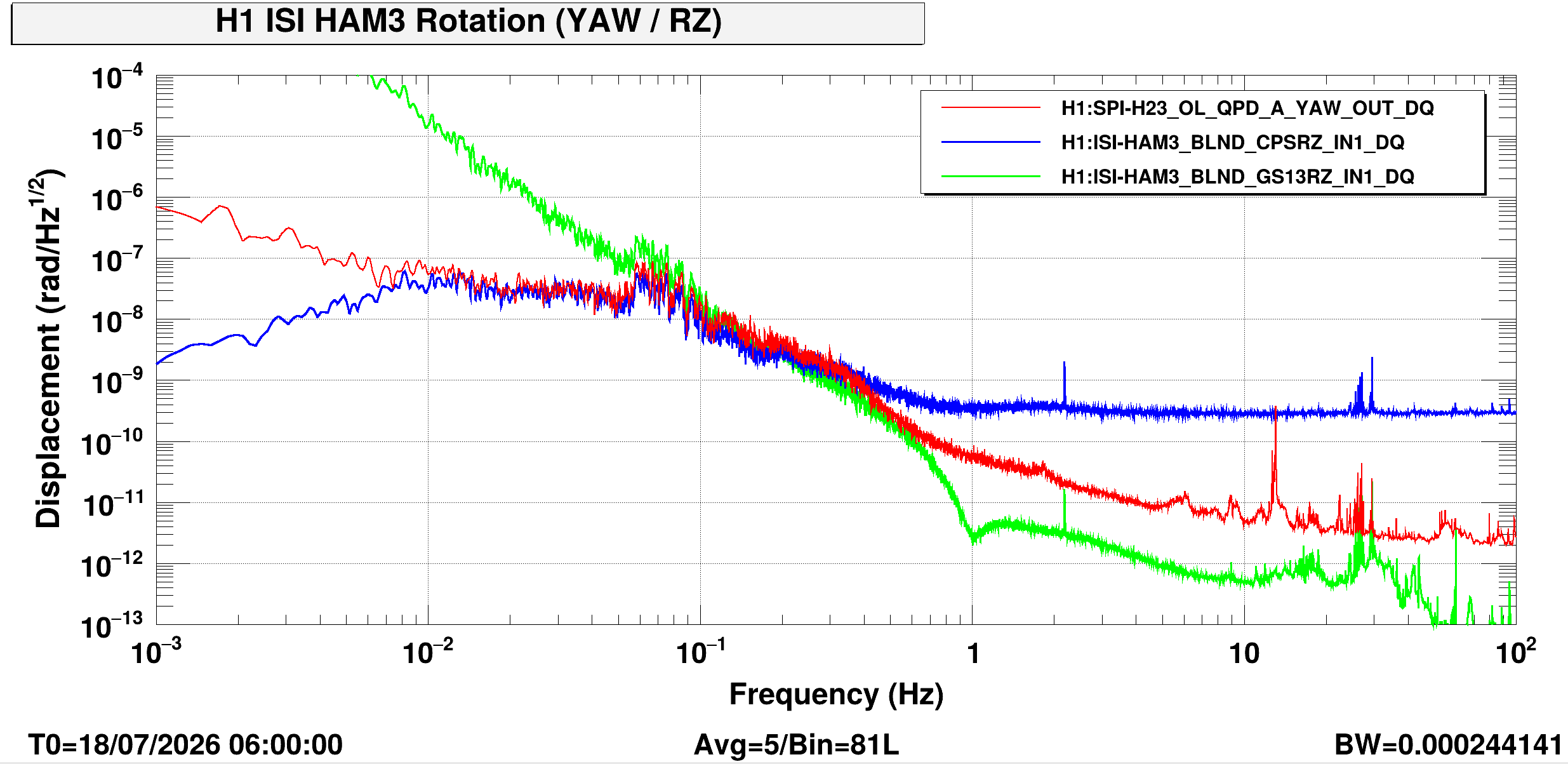
Here's the YAW ASD (sans a CRS of course), with GS13 and CPS calibrated with the same Arnaud calibration, and SPI OL YAW calibrated with the same 209.6 [urad/rad].

As expected -- more coherence than PIT, measuring real (but different) signal below ~0.5 Hz.
Compare with Figure 1biii.3 from the Final Design Doc T2400145.
The SPI ISI HAM3 OL YAW likely loses coherence below 0.01 Hz because the QPD again becomes dominated by ADC noise, because of the large spot.
Images attached to this comment