Keita, Louis, Elenna
Today, we proceeded to look for the input alignment, given all the changes that occurred in HAM2 during the ISS install, 90545. Although we have been able to lock PRX, we have not yet seen any beam on ASC-POP_A or B QPDs (they capture the forward POP beam).
To start, we locked the JAC and IMC, and aligned PRM. We could see the usual beam on the ISCT1 REFL camera. We noted that the beam position on IM4 trans QPD was far from center, about 0.26 in pitch and 0.66 in yaw. The IM4 trans NSUM was about 1.825 W, which is similar to a pre-vent value of 1.842. At this time the IM3 sliders were P: 40.3 and Y: 655.6. We confirmed that the IM sliders were where we expected them to be set due to the vent work.
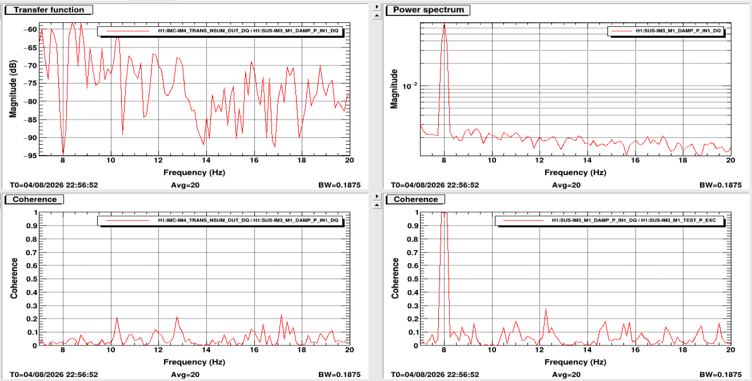
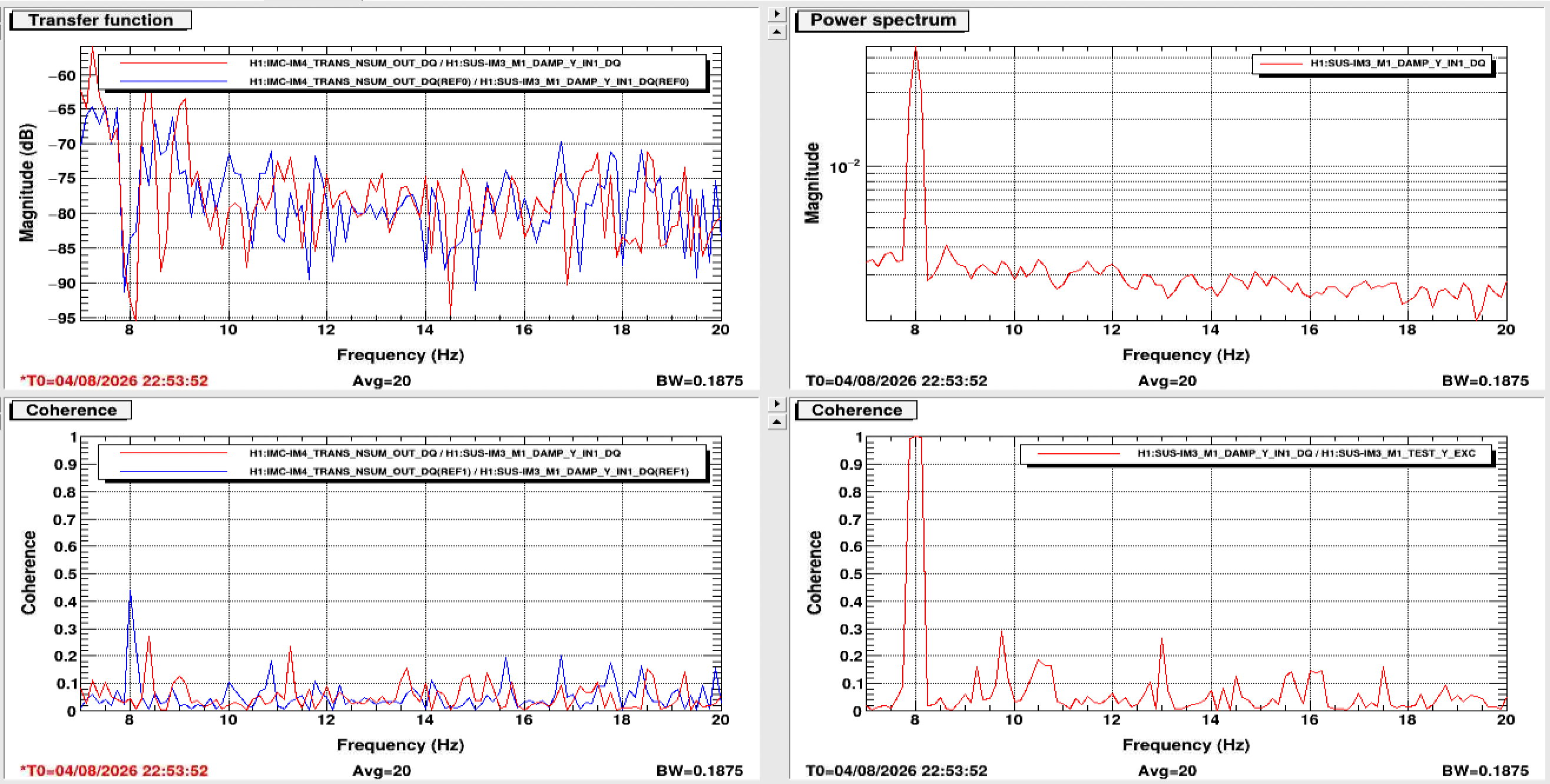
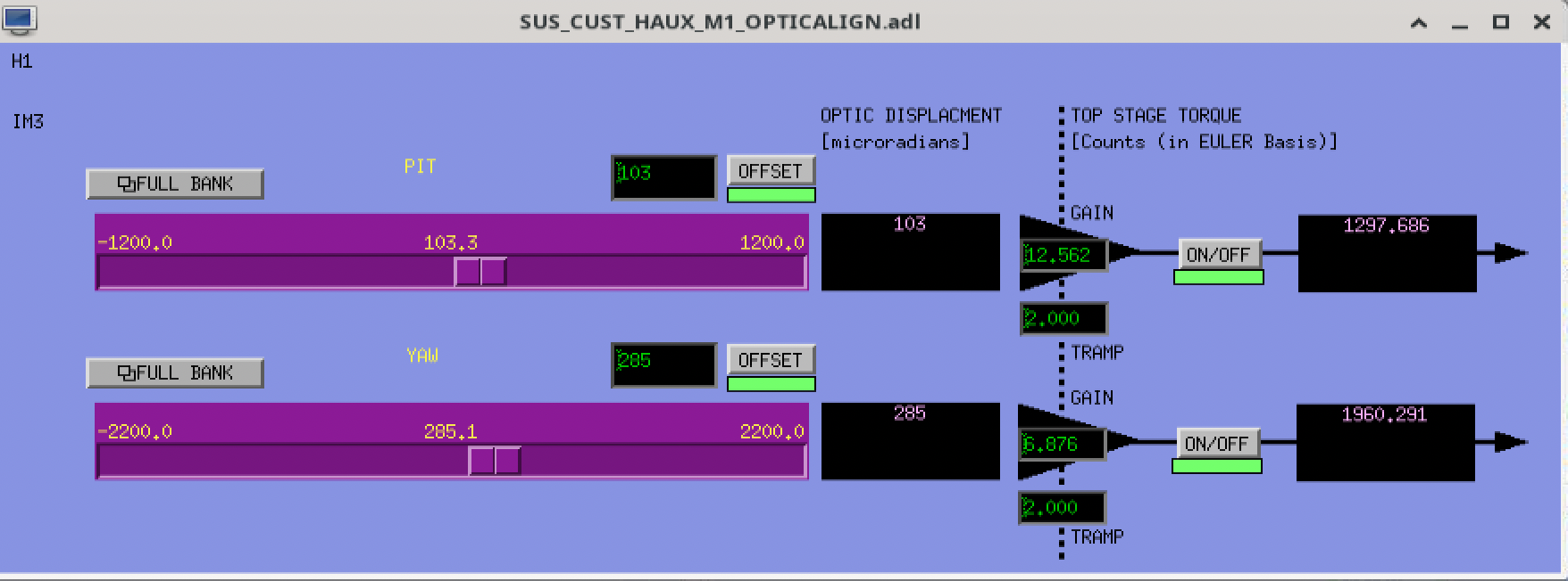
I moved IM3 sliders to center the beam on IM4 trans QPD, so new slider values were P: 103.3 and Y:472.6. Then, following Keita's direction, I proceeded to measure a transfer function of IM1 P and Y and IM3 P and Y to the IM4 trans NSUM as a way to quantify possible clipping in the input path. IM1 coupling should indicate clipping somewhere along the IFI, which includes some baffles. IM3 coupling should indicate clipping on the baffle between IM3 and 4.
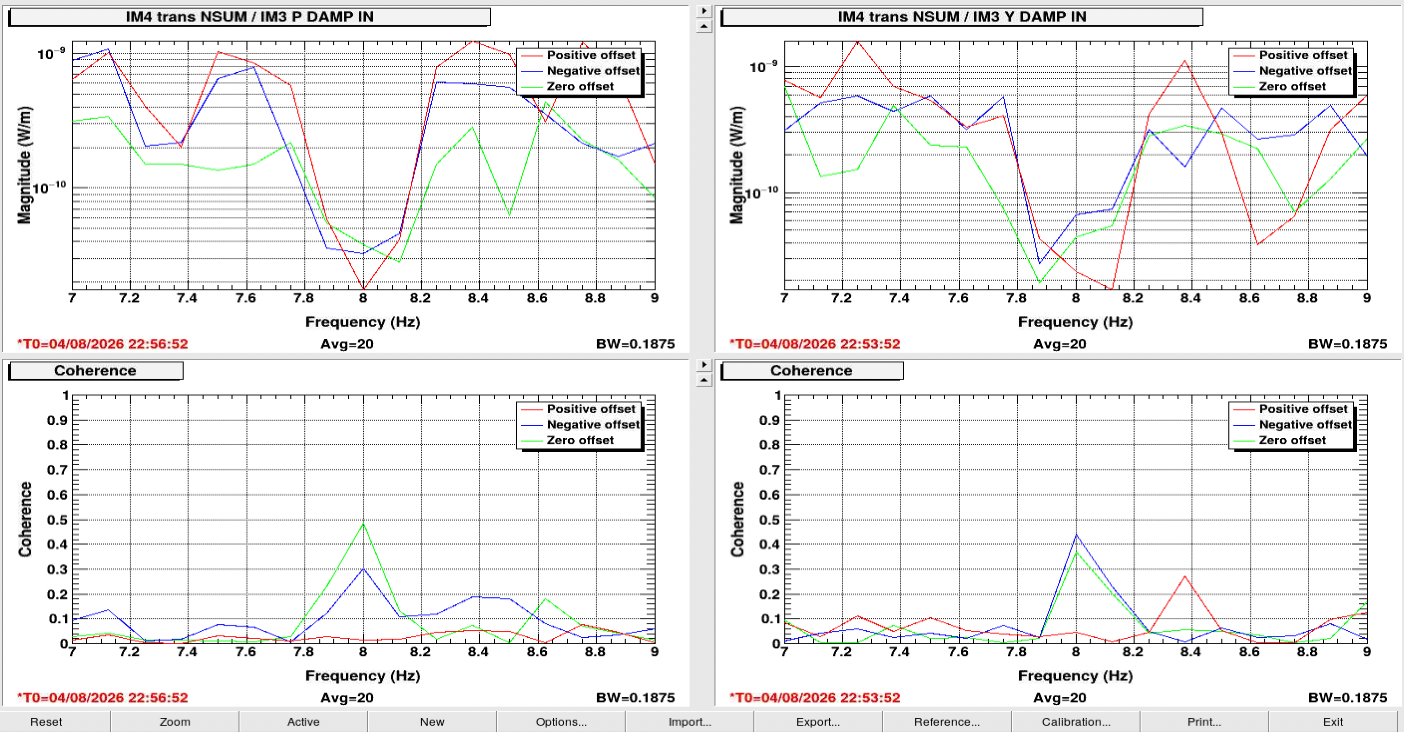
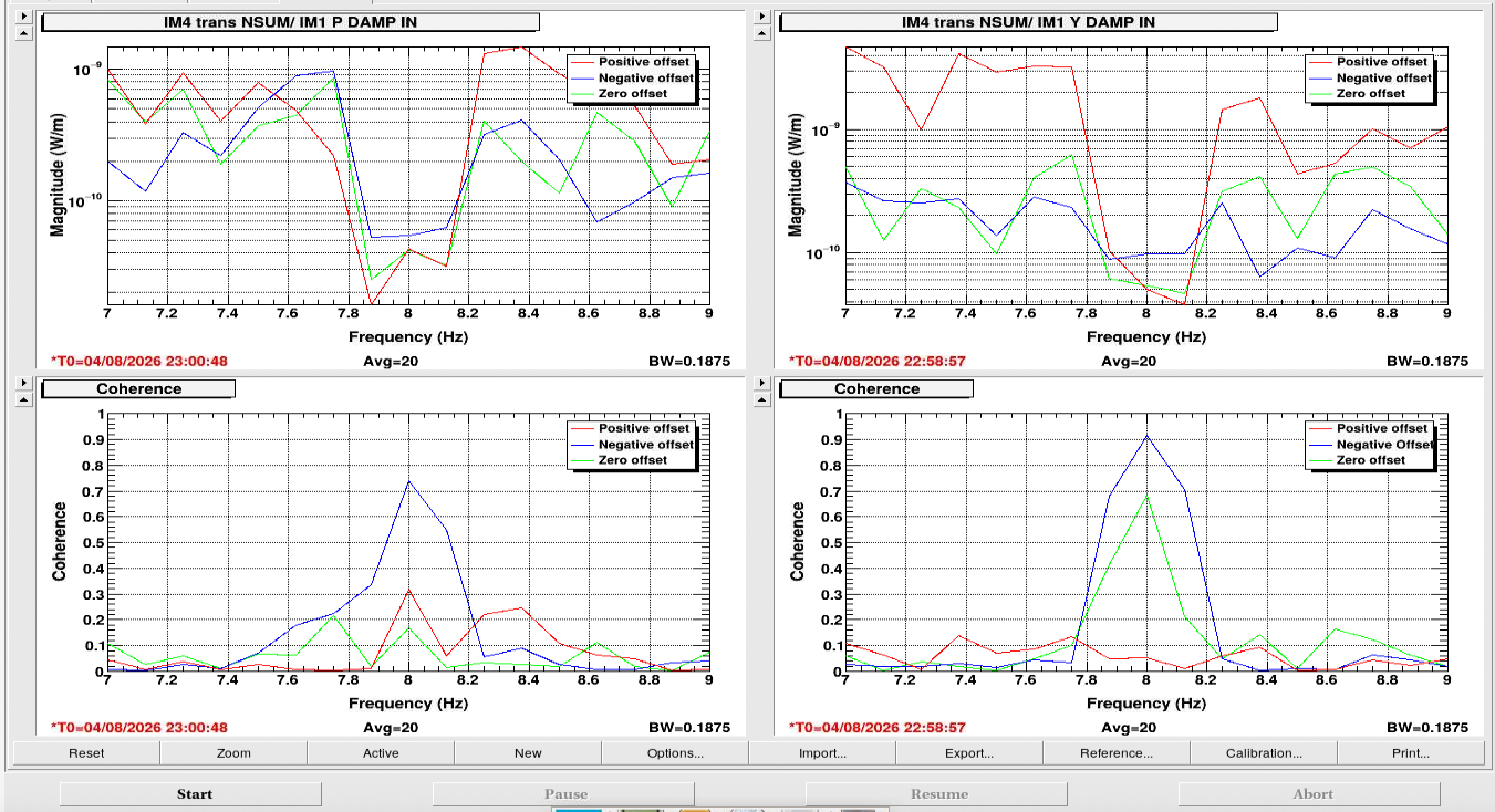
The first four screenshots show those results, which I obtained by driving a 30 ct excitation from the test bank of each suspension dof at 8 Hz. IM1 P, IM1 Y, IM3 P, IM3 Y
Next, Keita turned off the IMC ASC and moved JM3 to bring the beam to a position on MC2 trans that recreated the beam position he found during the vent. He set a yaw offset of -0.64 on MC2 trans and then re-engaged the IMC ASC. After the ASC converged, I recentered the beam on IM4 trans using IM3 again. We confirmed that the NSUM on IM4 trans returned to 1.825. I reran the same coupling test above and we saw that for all four dofs, the coupling to IM4 trans NSUM increased. This is evident in both increased coherence and coupling value at 8 Hz. IM1 P, IM1 Y, IM3 P, IM3 Y
Then, Keita flipped the sign of the yaw offset to +0.64, since there is some confusion about which way the sign goes on that QPD. I recentered the beam again on IM4 trans, confirmed the NSUM came back to 1.825 , and reran the coupling measurement. The results show that for all four dofs, the coupling is decreased to below the starting value, shown in both the coherence and coupling value. IM1 P, IM1 Y, IM3 P, IM3 Y
It's possible that we are confused about the sign on MC2 trans, so that the first offset Keita tried actually went to the wrong position.
Another confusing point is that we see coupling in both pitch and yaw, and beam movement in both pitch and yaw. However, the beam translation we did was yaw only, to relieve yaw clipping.
Since we had found what we believe was a better beam position in HAM2, we checked the REFL alignment. With PRM aligned in this alignment, the beam is on the edge of the ISCT1 refl camera, so not great. There was also very little beam on the REFL WFS, and trying to run the REFL WFS centering servos rails RM2. We are now concerned about the REFL path and possible clipping on the REFL baffle in HAM2 as well.
To finish, Keita turned off the MC2 trans offset, and I reverted the IM3 sliders to the start position. However, the final screenshot here shows the final IM3 position we found where we think we had very little clipping in the input alignment.
None of theae alignments helped us find the beam on ASC POP A, but that's not surprising since we didn't make any IM4 moves. As we finished, Keita set up a long raster of IM3 and IM4 to look for a beam on those QPDs.
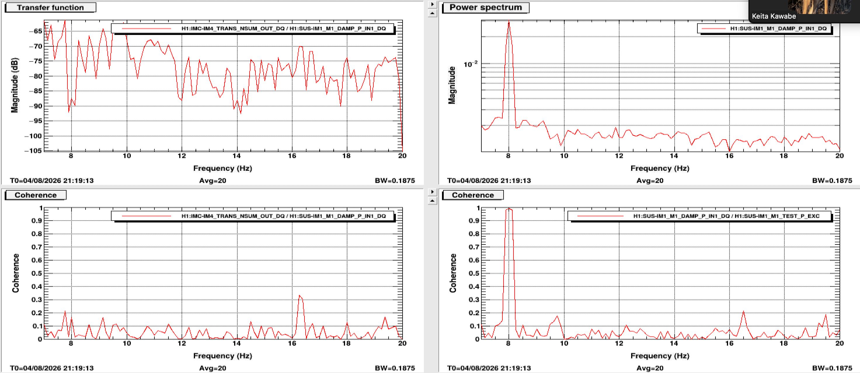
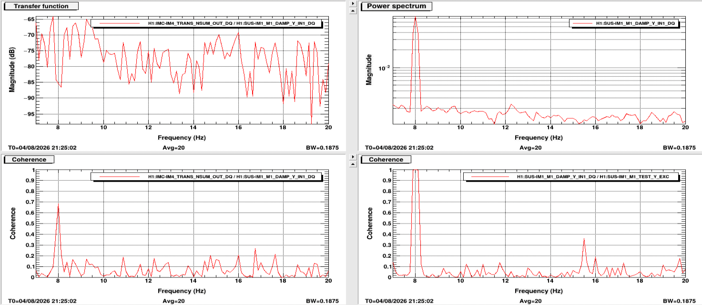
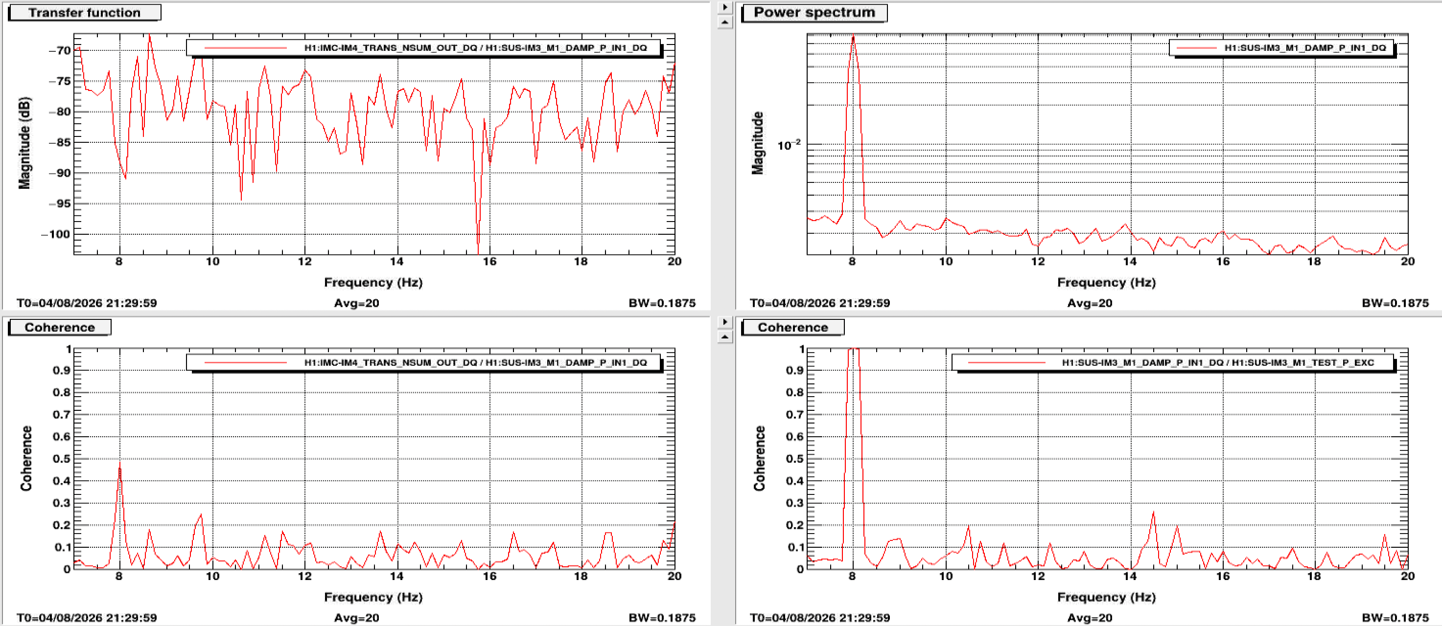
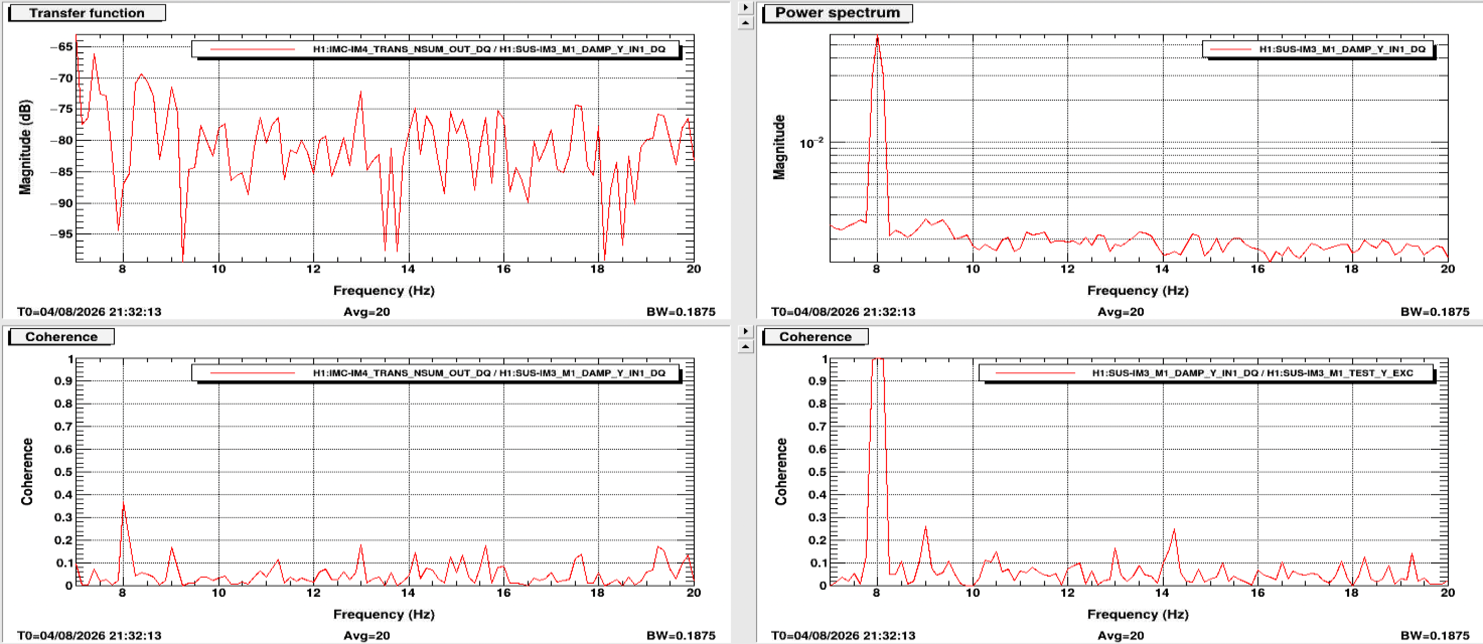
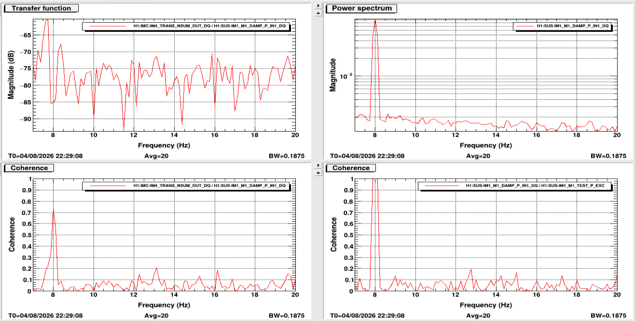
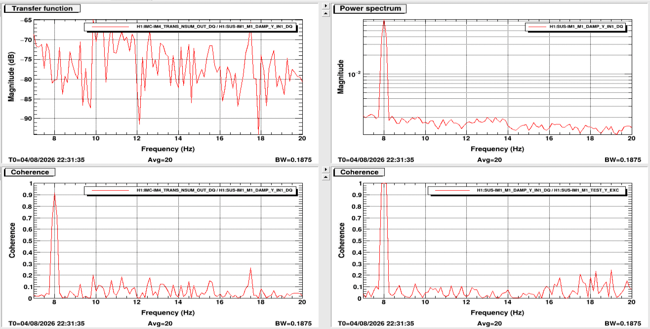
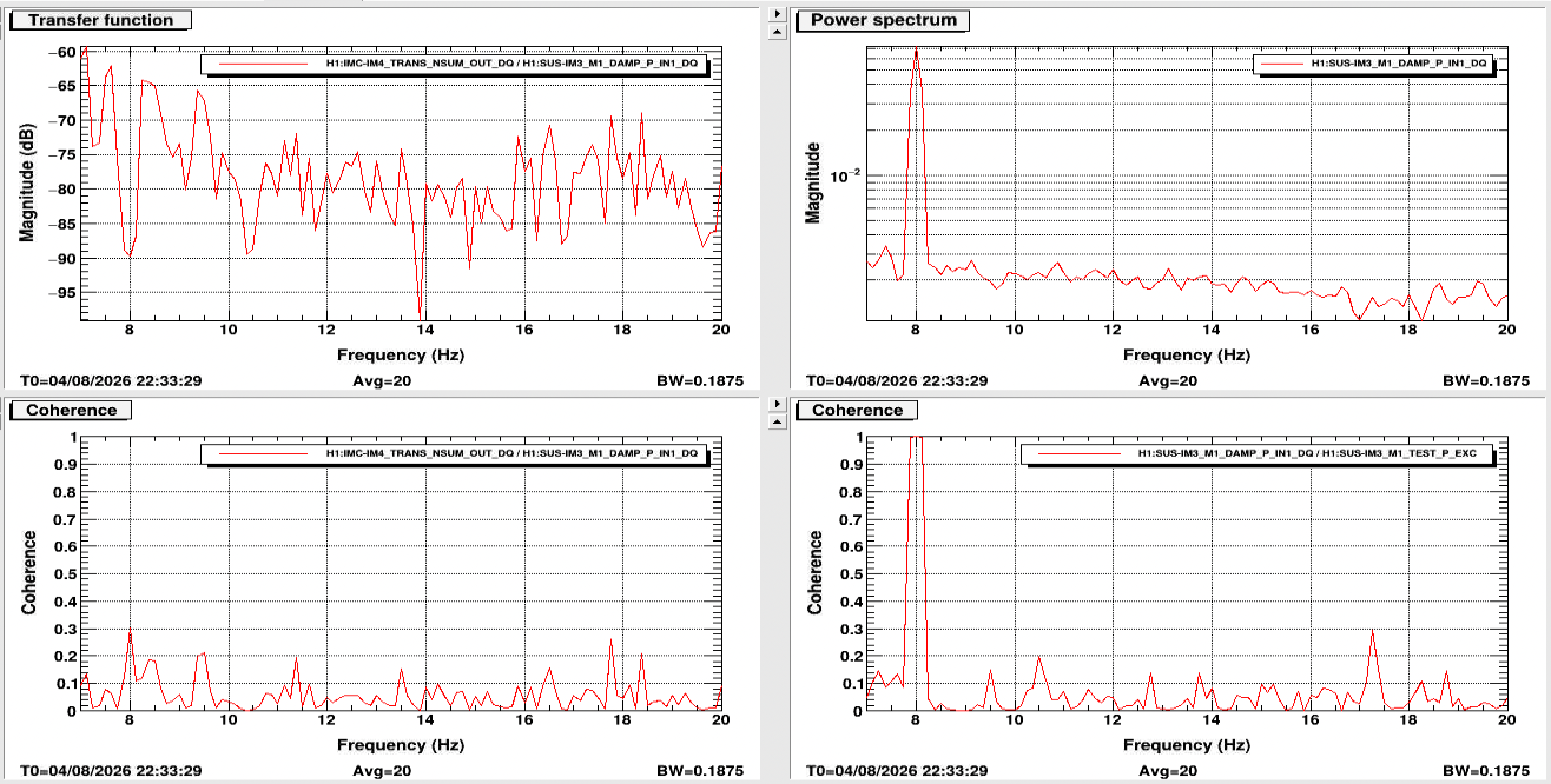
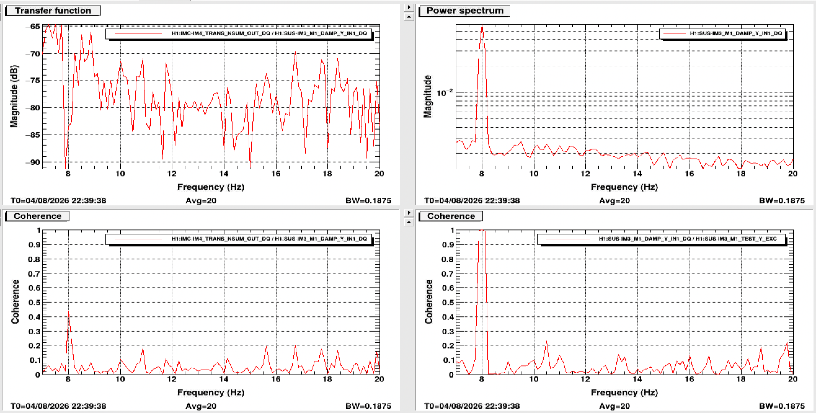
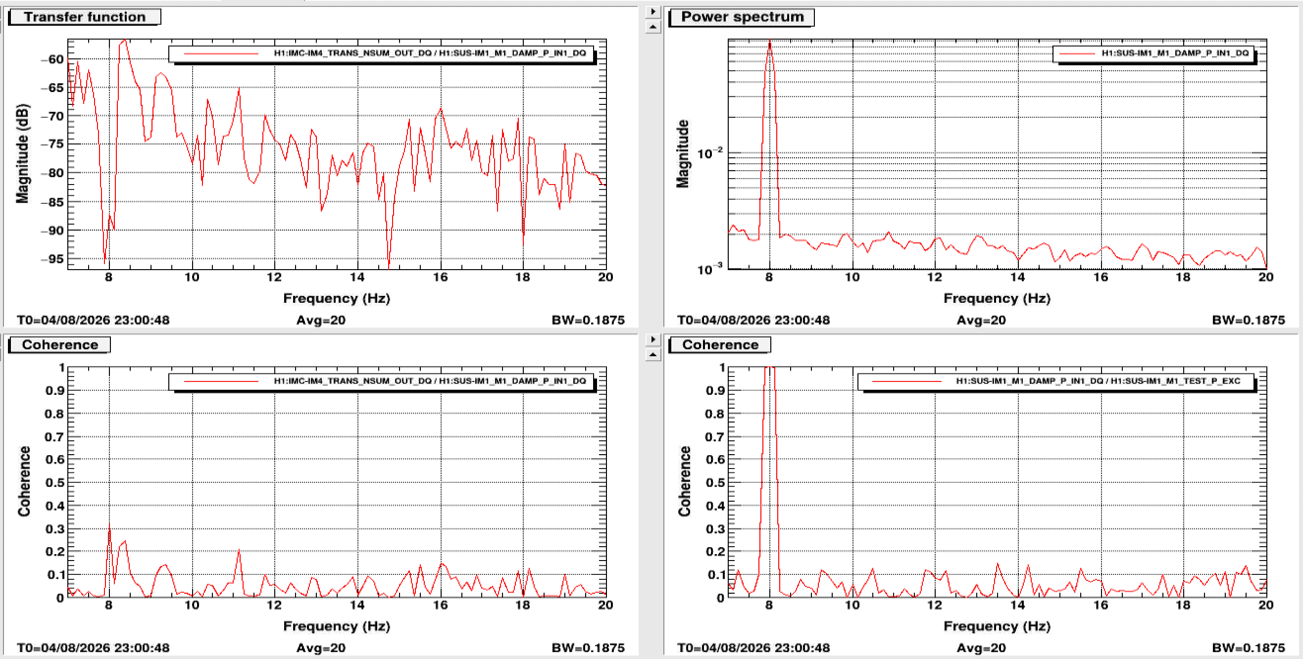
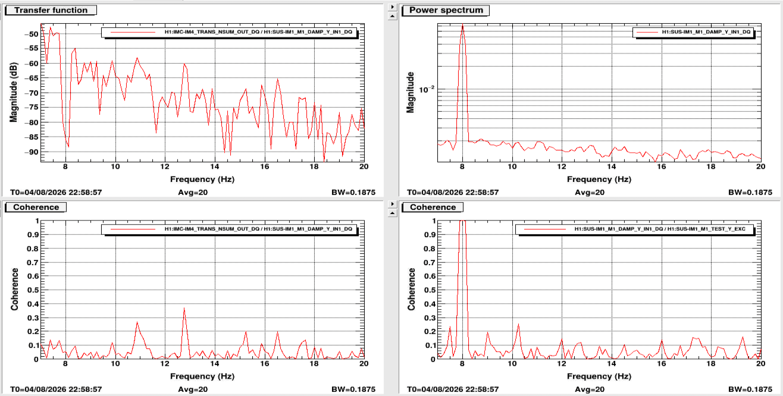
> transfer function of IM1 P and Y and IM3 P and Y to the IM4 trans NSUM as a way to quantify possible clipping in the input path. IM1 coupling should indicate clipping somewhere along the IFI, which includes some baffles. IM3 coupling should indicate clipping on the baffle between IM3 and 4.
The point is that IM3 to IM4_TRANS TF excludes the clipping between IM1 and IM3. Of course the TF from IM1 to IM4_TRANS can also show the clipping downstream of IM3 (such as baffles between IM3 and IM4).
> Next, Keita turned off the IMC ASC and moved JM3 to bring the beam to a position on MC2 trans that recreated the beam position he found during the vent.
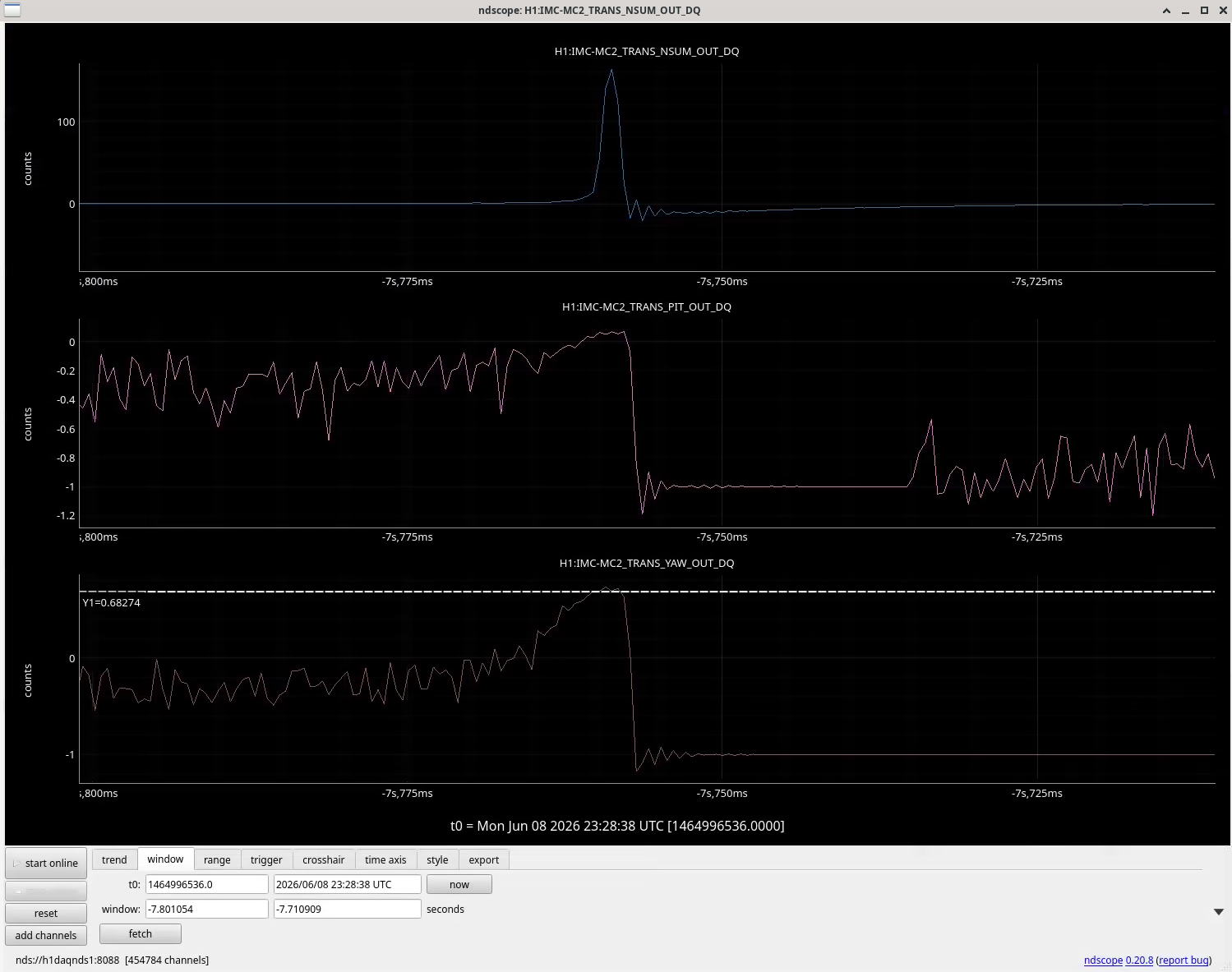
Turned off the IMC ASC in a hope that MC1/2/3 were all hanging at the same angle as they used to during the in-air work. (Moving JM3 won't change the beam position on MC2 when ASC was not working, it just improves the matching into IMC.) Without ASC, MC2_TRANS YAW was 0.64.
I did this because of my recollection that we intentionally off-centered the MC2 in YAW, but that was wrong, what actually happened was that we did center the beam spot on MC2 because it was initially off in YAW but not in PIT, the only thing was that people including myself were somewhat suspicious about the MC2_TRANS path at the time, so marked the horizontal beam spot position in HAM3 using vertical hard edge put on the ISI surface and then measured the distance from the edge to the neighboring screw holes on the ISI surface.
I trended MC2 TRANS back to the time when Rahul and I finished centering the IM4_TRANS path using IMC flashes (alog 90536). Unfortunately we cannot see fast channels for individual segments but some flashes were long enough (short but lasted for ~3 clock cycles for 2kHz system) to produce meaningful PIT and YAW signals in MC2_TRANS, see Screenshot2026-08-05003532.png. It was 0.68 in YAW, not that different from 0.64.
Anyway I just put an offset of -0.64 to MC2_TRANS YAW and re-engaged IMC ASC to the beam spot on MC2 won't move in YAW.
I also tested the other side of MC2_TRANS.
As Elenna showed, the coupling from IM1/3 dither to IM4_TRANS changed with the MC2_TRANS YAW offset. Positive offset was better than zero offset which was better than negative offset.
As of now I cannot tell if this level of coupling is significant enough or not, we'll need beam propagation math to be able to say anything.
> Since we had found what we believe was a better beam position in HAM2, we checked the REFL alignment. With PRM aligned in this alignment, the beam is on the edge of the ISCT1 refl camera, so not great.
This is not surprising because we caused non-negligible change in the beam going into PRM and the beam was not retro-reflecting. On top of that, since IMC alignment change will change the alignment of the IFO REFL beam going into HAM1 even if PRM retroreflects.
However, with zero offset in MC2 YAW, without much care/attention to IMs,
- the IFO refl beam makes it to the ISCT1, and
- we can center ASC REFL A and B using RMs without railing them.
That's already a sign of reasonable alignment. If we'll have to do a major rework of HAM2 to accomodate MC2_TRANS YAW offset, that seems to be a sign that the IMC is all in all different from where it was in-air desipite the MC2_TRANS YAW position of in-air flashes.
As a side project, I'll let Elenna and/or Louis measure the MC2 beam position offset by a2l without MC2_TRANS YAW offset as the intent was to center MC2.
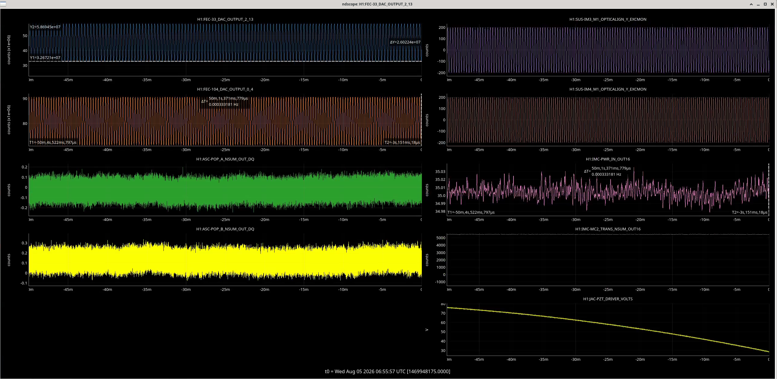
I scanned IM3 (+-200urad, 0.043Hz) and IM4 (+-200urad, 0.053Hz) at the same time in YAW to find beam on POP_A and/or POP_B. With these frequencies, one scan cycle is exactly 1000seconds.
Laser power was increased to 35W. Whitening gain was nominal 12dB without any whitening filters, and there is -12dB gain in the digital to compensate.
PRM transmission is ~3%, PR2 transmission is ~230ppm and there's 90:10 splitter in the POP A/B path that throws away 90% of the power. Each QPD receive roughly half of that, i.e. 35W*3%*230ppm*0.1/2~ 12uW, which is not large but large enough so we can clearly see something if we believe the POP segments calibration (1 ADC count = 0.19 uW with 12db whitening gain and -12dB digital gain).
But I don't see anything, not 12uW, not even 1uW, really nothing. Attached is the trend for 3000 seconds. Are POP QPDs working? Connected?
I lowered the power to 2W and stopped excitation after the scan was done.
The plots I attached to my original alog are kind of impossible to parse, so I remade them comparing each dof at each offset. I also added in the calibration to the xml file, IM4 trans NSUM is calibrated into W and the damp ins of each suspension is ideally calibrated into urad. Now the transfer functions show real units, so they are more physically meaningful.
As a reminder, I drove the exact same excitation strength for each injection, 30 ct, and the line injected was almost 2 orders of magnitude above the noise in each damp inmon. Each measurement was run for 20 averages, 8 s BW with 50% overlap.
If you want to read the exact values in the file, you can find the xml template in my home directory (ligo/home/elenna.capote) as IM4_trans_coupling_calibrated.xml