louis.dartez@LIGO.ORG - posted 15:27, Friday 07 August 2026 (91447)
New input alignment settings for IM1, IM2, and IM3
K. Kawabe, E. Capote, L. Dartez

This log covers work that started yesterday. We set out to scan the IM1 pointing to see if we could find evidence of clipping and to potentially identify a preferred input pointing configuration. We applied a dither to the IM1 and IM3 suspensions to use IM4_trans and the ISS second loop QPDs as sensors. This test was laborious because each new IM1 pointing mis-centered the beam on both QPDs. Keita pointed out that we can use IM2 and IM3 to center the beam on the IM4_trans and ISS second loop QPDs, respectively. Moreover, by centering the beam on IM4_trans and the ISS second loop QPDs, we get the beam for free on the POP QPDs (even though it is not centered there). To support the argument that we can arrive on a pointing now that will be relevant once we open the arms, we note that the QPD NSUM levels for the IM4_trans, ISS second loop, REFL WFS A and B QPDs are all consistent with what we had in O4 at 2W. The NSUM levels of the POP QPDs is consistent with what we had in O4 at 2W straight shot (PRC misaligned) as well. During this test we paid particular attention to avoid moving the input alignment to a spot that would have the RMs near their actuation range to keep the beam centered on the REFL QPDs.


For each IM1 pointing trial we did the following:

1. Move IM1 alignment to new trial position
2. Walk the alignment of IM2 and IM3 to center the beam onto IM4_trans QPD and the ISS Second Loop QPD (within about 0.04 in PIT and YAW). I used IM2 to center the beam onto IM4_trans and IM3 to center it onto the ISS Second Loop QPD.
3. Check that the beam hasn't fallen off of the REFL PDs or the POP PDs and that the NSUM, PIT, and YAW signal values are at roughly the same values as they were before the IM1 adjustment.
4. Run the DC centering loops to center the beam on the REFL PDs and ensure that the RMs are not close to their actuation range.
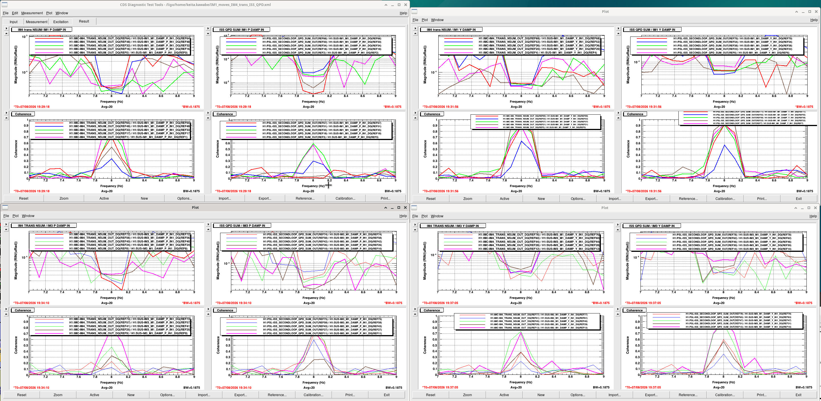
5. Measure the transfer function from the IM1 and IM3 DAMP banks to the IM4_trans and ISS second loop QPD SUM channels while injecting an 8Hz excitation into the IM1 and IM3 SUS TEST banks.

The IM1 trials we tried are as follows:

Nominal position (the IM1 position when we began): 524.2 / -386.6 (P/Y)

Trial 1 (pink): (+30 uRad Yaw): 524.2 / -356.6 (P/Y)
Trial 2 (brown): (-50 uRad Yaw): 524.2 / -436.6 (P/Y)
Trial 3 (green): (-10 uRad Yaw): 524.2 / -396.6 (P/Y)
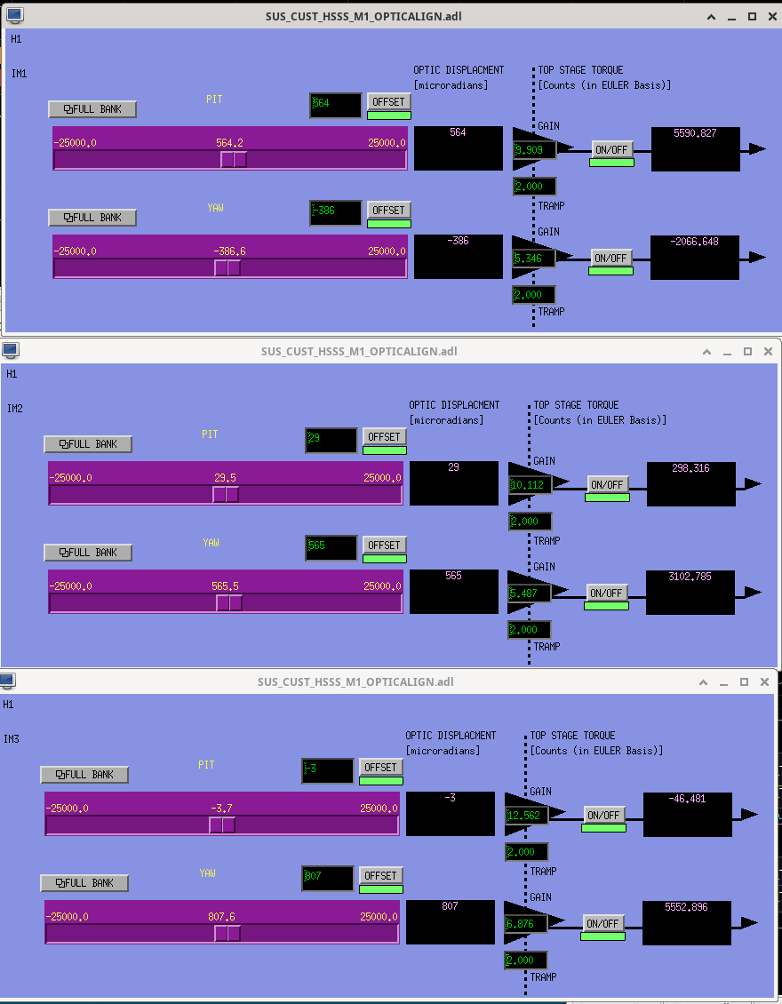
Trial 4 (blue): (+40 uRad PIT): 564.2 / -386.6 (P/Y)
Trial 5 (red): (-40 uRad  PIT): 484.2 / -386.6 (P/Y)

The five trials for this test were split across two days. And the excitation amplitude was not necessarily constant across all 5 measurements. This made it difficult to compare today's measurements against yesterday's. In any case, we think that the position at Trial 4 is the best one so far in that it shows the lowest coherence between the dither at IM1/IM3 and the IM4 trans QPD. We do not know or think it is unilaterally the best position, but we think it is better than it was before we started this. We won't know more until we have the arms.

The new slider values for IM1, IM2, and IM3 are in IM_alignment_sliders.png. A screenshot of the TFs we took is at blueisgood.png. The colors of the traces correspond to the color next to each trial listed above. The blue trace has the best coherence for most of the measured transfer functions (and for all of the IM4_trans measurements). The DTT template we used can be found at ~keita.kawabe/IM1_moves_IM4_trans_ISS_QPD.xml.
Images attached to this report