Summary
We have calibrated the two JAC steering actuators the PZT (IO_MB_M4) and the JM1, in μrad per drive count at DC. The scale comes from the second harmonic of the cavity transmission under a dithered drive, which is insensitive to DC misalignment and so needs no external angle reference.
Method
By expanding the injected field in the cavity's own eigenmode basis, we can describe the misaligned as,
Ein(t) = E0 + δ(t) E1
with E0 the cavity's TEM00 mode and E1 the TEM10 (pitch) or TEM01 (yaw) mode, orthonormal. As long as the misalignment is small enough comparing to the beam size, the single complex coefficient δ carries the whole misalignment on that axis: its real part is a transverse displacement in units of the waist size, its imaginary part an angle in units of the divergence angle. Only the TEM00 is resonant, so the transmitted power follows the fraction of the input that sits in E0, i.e. 1 − |δ|2 for |δ|2 « 1.
Dithering a steering actuator makes δ oscillate about whatever value it already had:
δ(t) = δofs + δa cos(2πft)
where δofs is the static misalignment already present, and δa is the dither we deliberately applied, which is exactly the quantity we want in order to calibrate the actuator. TRANS signal (1 − |δ|2) can devided into three components with its frequecies:
frequency |
value | contains the unknown δofs? |
|---|---|---|
| DC | |δofs|2 + |δa|2/2 |
yes |
f |
2 Re(δofs*δa) |
yes — magnitude and relative phase |
2f |
|δa|2/2 |
no |
The static offset drops out of the second harmonic algebraically. 2f therefore delivers |δa| with no reference to the alignment state we happened to be sitting at, and with no external angle standard. The DC and f terms, the two one would reach for first, are both contaminated by it.
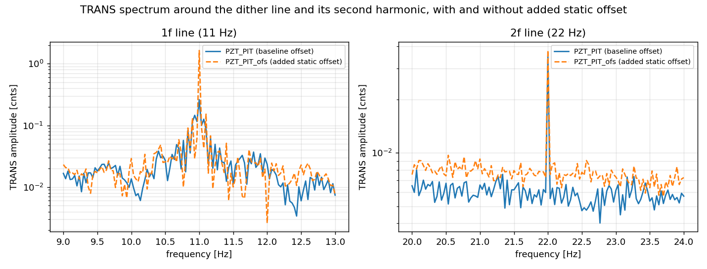
This is the whole point of the method, and it is directly visible in the plot. adding a static offset grows the 1f line by +528 % while the 2f line moves by +8 %, its own measurement noise.
Measurement
I proceeded 4+1 measurement in total with the JAC locked. For each measurement, one actuator axis was dithered at 11 Hz, with the excitation injected on the channels below and the drive read back on the corresponding _OUT. I excited JM1/PZT PIT/YAW per one measurement, and the other one is the PZT_PIT excitation with static offset (30 cnts) to demonstrate that the 2f peak is not affected by the offset. Transmission was read on H1:JAC-TRANS_A_LF_OUT.
| record | excitation channel | drive read back on | amplitude at 11 Hz [cnt] | drive offset [cnt] | TRANS DC [cnt] |
|---|---|---|---|---|---|
PZT_PIT |
H1:JAC-PZT_PIT_EXC |
H1:JAC-PZT_PIT_OUT |
20.0 | 0 | 6451.2 |
PZT_PIT_ofs |
H1:JAC-PZT_PIT_EXC |
H1:JAC-PZT_PIT_OUT |
20.0 | 30 | 6442.5 |
PZT_YAW |
H1:JAC-PZT_YAW_EXC |
H1:JAC-PZT_YAW_OUT |
20.0 | 0 | 6442.6 |
JM1_PIT |
H1:SUS-JM1_M1_TEST_P_EXC |
H1:SUS-JM1_M1_TEST_P_OUT |
40.0 | 0 | 6445.5 |
JM1_YAW |
H1:SUS-JM1_M1_TEST_Y_EXC |
H1:SUS-JM1_M1_TEST_Y_OUT |
40.0 | 0 | 6440.2 |
|δa| is calculated from peak heights of the transmission at 22 Hz, converted to a mirror tilt using the local beam radius at each actuator from the current JAC reflected-path layout model (alog91472 comment), and calibrated into DC responce using each actuator's frequency response as measured (described below).
Results
| actuator | axis | excitation channel | |δa|2 |
efficiency [μrad/cnt] | |
|---|---|---|---|---|---|
| at 11 Hz (as measured) | at DC | ||||
| PZT | PIT | JAC-PZT_PIT_EXC |
1.09e-5 | 0.0093 | 0.083 |
| PZT | YAW | JAC-PZT_YAW_EXC |
6.47e-6 | 0.0093 | 0.079 |
| JM1 | PIT | SUS-JM1_M1_TEST_P_EXC |
1.01e-5 | 0.0216 | 0.89 |
| JM1 | YAW | SUS-JM1_M1_TEST_Y_EXC |
1.67e-5 | 0.0254 | 0.92 |
The 11 Hz column is what the dither actually produced; the DC column is that value divided by the actuator's own response at 11 Hz, and is the number to use for a DC gain.
Appendix
Actuator frequency response
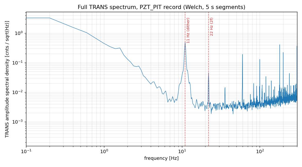
The frequency response itself comes from a separate set of four broadband actuator-to-wavefront-sensor records (300 s each, one actuator per record, see atatched plots), from which the JM1 suspension resonance and the PZT drive pole are fitted. Only the shape of those transfer functions is used; their absolute scale plays no role in the calibration.
The fitted frequency responses are:
- JM1 — complex pole pair,
f0 = 2.00 Hz, Q = 7.7(PIT) and1.80 Hz, Q = 5.4(YAW) - PZT — single real pole at
fp = 1.24 Hz(PIT) and1.30 Hz(YAW)
AOI compensation
Both actuators sit at a design AOI of 45°, and the rows above include the geometric correction that follows. A tilt whose rotation axis lies in the mirror surface and in the plane of incidence steers the beam by only 2θ cos(AOI), against the full 2θ for the axis perpendicular to that plane. At the PZT the suppressed axis is YAW in the cavity-referred channel naming (the HAM1 periscope exchanges the transverse planes downstream of it); JM1 sits after that periscope, so for it the suppressed axis is PIT. The assignments follow from each mirror's orientation, and the correction uses the design 45° rather than a value fitted to the measured ratio.
Cross-checks
- JM1 against its own OSEM signal. I compared the numbers above with the OSEM output with a rough single DC-step reading. The difference between the calibration factor are: 1.17× (PIT), 1.02× (YAW).
- PZT against its design value. The design chain is
APZT = 500 μrad/V(T1500342) driven through an 18-bit DAC (±10 V differential, i.e. 20 V over 217 counts) and a differential-to-single-ended board (D1100457 v2, unity gain, read off its schematic), giving 0.076 μrad/cnt. No further driver gain applies on top, since the T1500342 figure is referenced at the controller's control input. Our result sits at 1.09× (PIT) and 1.04× (YAW) of this designed value.

Short note: a mirror rotated by θ, sitting where the beam radius is w(z), produces |δ| = k w(z) θ, and its phase relative to TEM00 is 90° plus the Gouy phase accumulated from the reference waist. This can be applied for the mirror which is transmitting the lens. This is because δ is the field amplitude of the first-order mode it is continuous across lenses, so a mirror separated from the reference space by lenses is handled by simply adding up the free-propagation Gouy phase to the reference waist. The table below therefore carries the beam radius and the accumulated Gouy phase at each actuator.
| actuator | axis | excitation channel | |δa|2 | efficiency [μrad/cnt] | beam radius w [mm] |
Gouy phase from the JAC waist [deg] |
|
|---|---|---|---|---|---|---|---|
| at 11 Hz (as measured) | at DC | ||||||
| PZT | PIT | JAC-PZT_PIT_EXC | 1.09e-5 | 0.0093 | 0.083 | 3.020 | -86.4 |
| PZT | YAW | JAC-PZT_YAW_EXC | 6.47e-6 | 0.0093 | 0.079 | 3.270 | -73.5 |
| JM1 | PIT | SUS-JM1_M1_TEST_P_EXC | 1.01e-5 | 0.0216 | 0.89 | 0.620 | -32.7 |
| JM1 | YAW | SUS-JM1_M1_TEST_Y_EXC | 1.67e-5 | 0.0254 | 0.92 | 0.681 | -30.8 |
The beam radius (1/e2 intensity) and the Gouy phase are model values at the actuator, taken from the JAC REFL optical model.