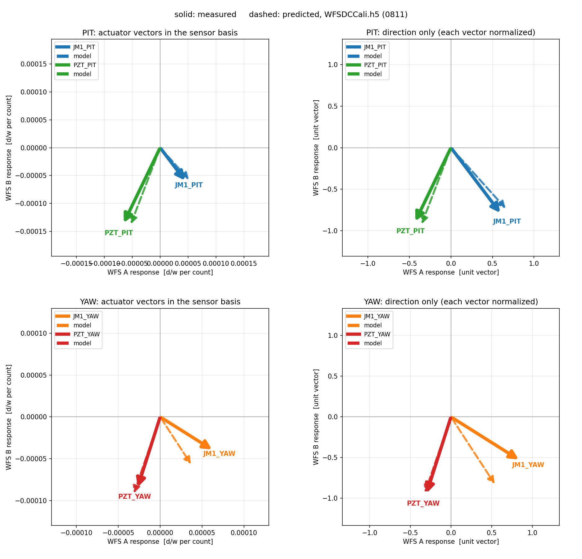
The JAC WFS DC signals were calibrated. The motivation for this measurement is to check that the optical layout model is right. With JAC unlocked the beam in reflection is close to a pure TEM00, and the DC quadrant signals calibrate easily by normalising with the beam size. That makes the unlocked DC a clean sanity check on the layout and on the calculation built from it.
What was done
- Unlock JAC.
- Centre the WFS A and WFS B DC signals using the picomotors.
- Two independent excitations:
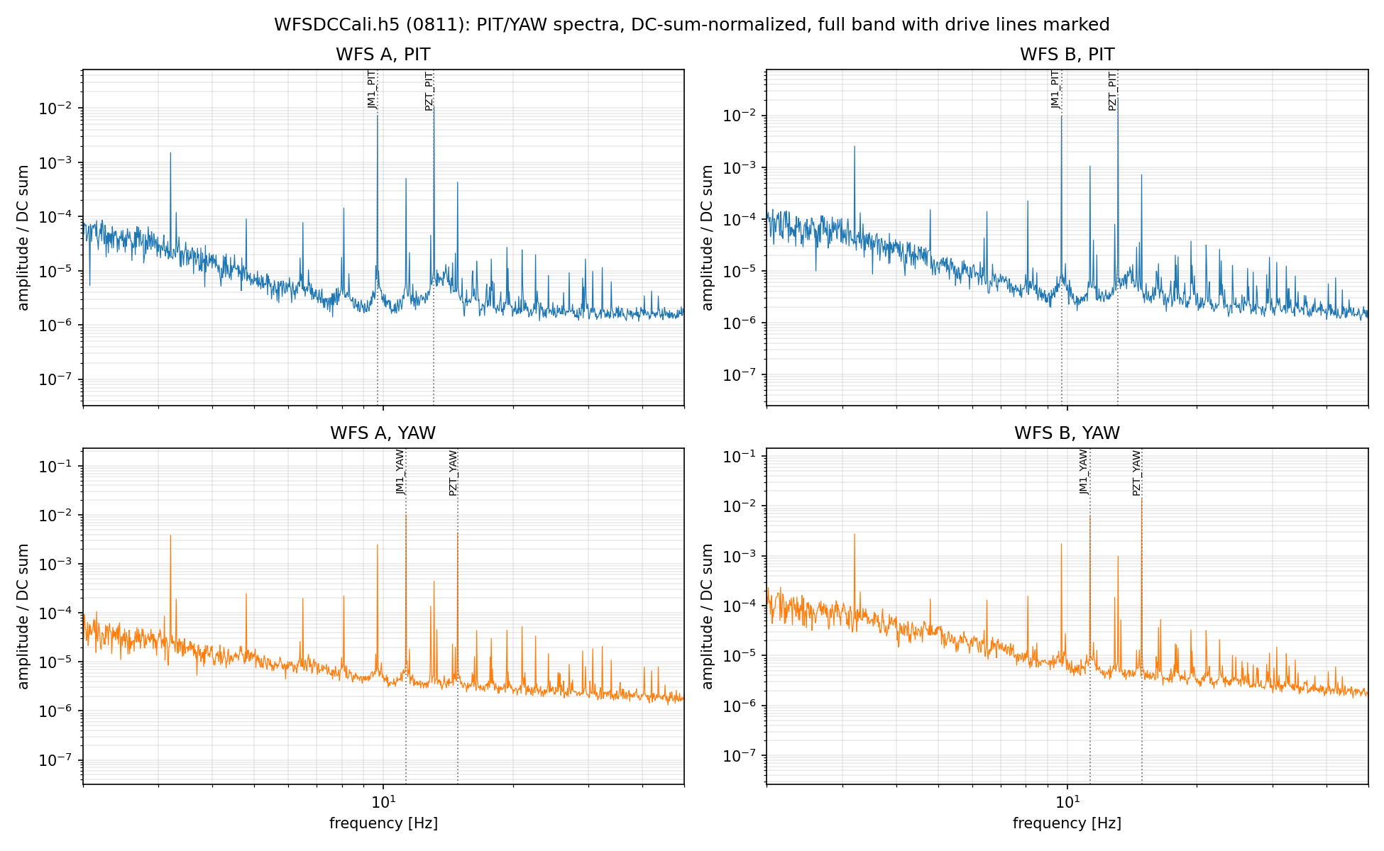
- (i) calibration lines. Four lines, one on each actuator (JM1 PIT 9.7 Hz, JM1 YAW 11.3 Hz, PZT PIT 13.1 Hz, PZT YAW 14.9 Hz), driven simultaneously; the peak height was read out at each WFS DC.
- (ii) broadband. White noise below 10 Hz injected into one actuator at a time, and the transfer function to each WFS DC measured.
What is predicted
The TEM10/TEM01 that each actuator generates is known in magnitude and phase from the actuator calibration and the layout model. At the WFS, these have rotated away from TEM00 by the accumulated Gouy phase between the actuator and the sensor. A DC quadrant photodiode reads the real part of the first-order mode amplitude at its own plane (more precisely, the real part of the odd modes), so the accumulated Gouy phase over that path fixes what the WFS DC signal should be. Nothing else is needed: the magnitude follows from the beam radius at the actuator, the phase from the accumulated Gouy phase.
Results
| actuator | sensor-basis direction [deg] | magnitude [(Δx/w) / cnt] | ||||
|---|---|---|---|---|---|---|
| predicted | measured | meas − pred | predicted | measured | meas / pred | |
| PZT PIT | -111.00 | -115.82 | -4.82 | 1.487e-4 | 1.520e-4 | 1.022 |
| PZT YAW | -108.96 | -107.68 | +1.29 | 9.790e-5 | 8.968e-5 | 0.916 |
| JM1 PIT | -47.99 | -52.90 | -4.91 | 7.967e-5 | 7.598e-5 | 0.954 |
| JM1 YAW | -56.87 | -32.19 | +24.68 | 6.895e-5 | 7.471e-5 | 1.084 |
The direction is the angle of the (WFS A, WFS B) response vector, and the magnitude is its length in units of normalised beam displacement per drive count. Three of the four lines agree with the prediction to within 5 deg in direction, and the magnitudes agree to within 8% (max/min 1.183 across the four, std(log) 0.064).
The two excitation methods agree with each other: comparing the sensor-basis direction obtained from the calibration lines against the one obtained from the broadband injection gives +6.79, +5.56, -0.24 and +0.19 deg for PZT PIT, PZT YAW, JM1 PIT and JM1 YAW.
JM1 YAW is the exception, off by +24.68 deg. Why this one line alone fails to be predicted is not yet understood. Several explanations were tried and none survived: moving JM1 along the beam would need 29 cm; moving WFS B by 2.5 cm removes the JM1 YAW discrepancy but drives JM1 PIT from -4.9 to -30 deg; the astigmatism degeneracy in the layout fit spans 2.1 deg against the 14.3 deg required; the ghost beam is ruled out because the result is unchanged across the ghost dump (we did same measurement before the ghost beam dump campaing); and the yaw to length coupling of the suspension would need to be of order 10 um for against the 0.003 um the JM1 OSEMs seee.