Jennie W, Sina K, Erik V
Summary: Error found in heterodyne phase calculation and has been fixed but we are still confused about the heterodyne amplitude calculation.
Today I checked the local oscllator signals, beat signal and demodulated signals to debug our demodulation problems.
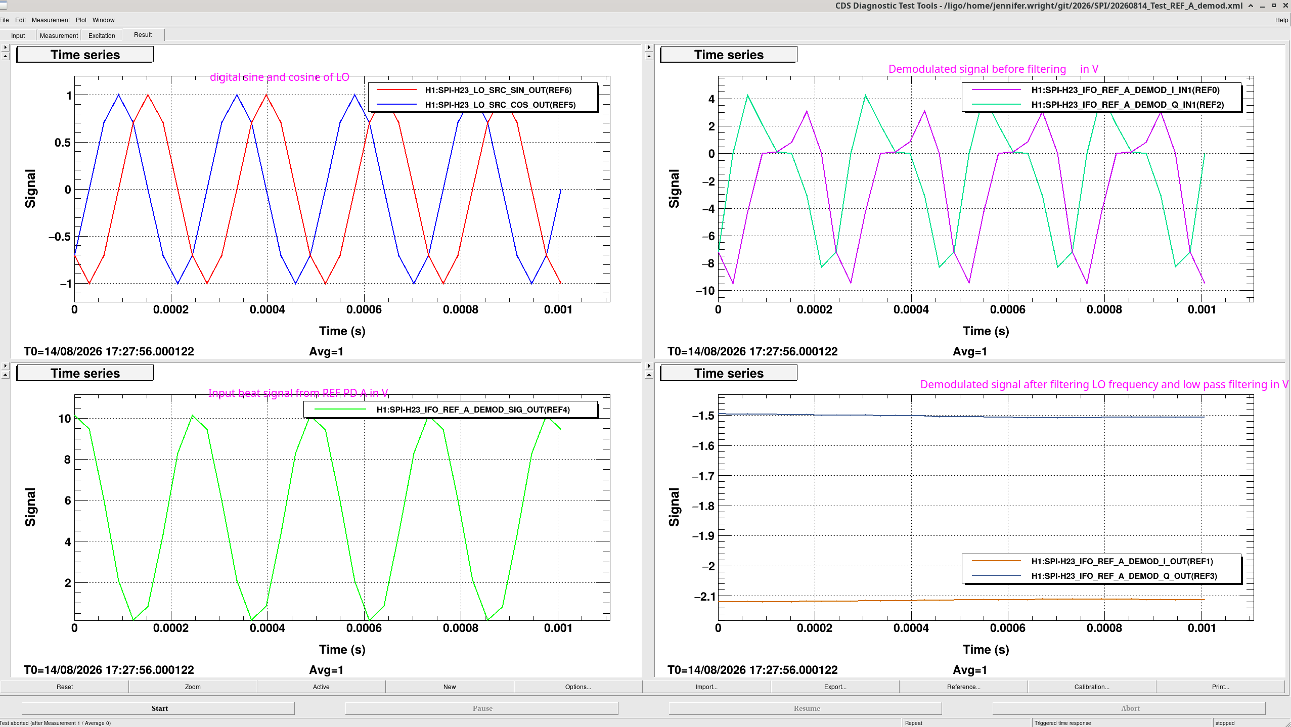
First check I did is with our nominal LO frequency of 4096 Hz. Top left plot is the sine and cosine signals from the digital local oscillator, bottom left is the beat signal from reference interferometer photodiode A.
Top right is the same signal after the demodulator in both I and Q. Bottom right is the demodulated signal after the filtering which has a comb at 4096 Hz and a low pass at 200 Hz.
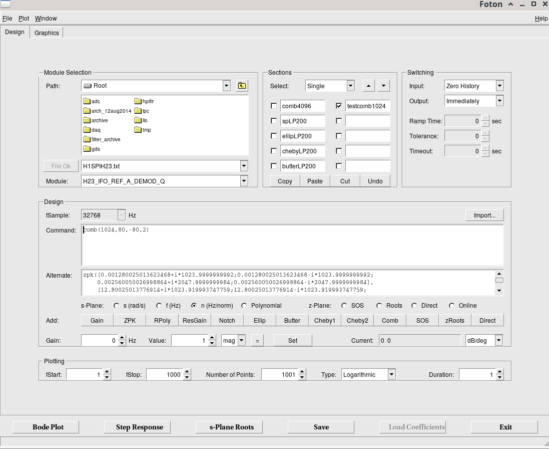
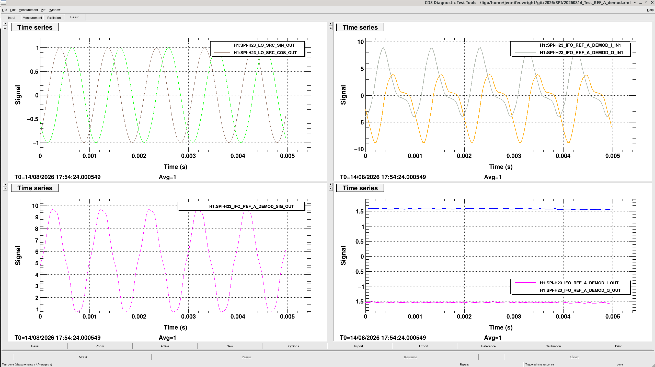
Then I did another check of the same channels using 1024 Hz (which means I had to replace the comb frequency we use to filter out the LO frequency in the demdulator output).
Looking at the REF A IFO output signal, where the cosine and sine of the local oscillator are shown on the top left plot and the beat signal from the PD before demodulation is shown on the bottom left.
From the raw we can see that even with the phase block we removed this morning, the calculated heterodyne amplitude should be ~10Vpp and the mean should be around 5V. This would give a heterodyne efficiency of nearly 10/(2*5) = 100% for the reference interferometer.
The calculated amplitude in the model however is shown as ~3V in the top right plot however. The calculated phase (harder to check if this is correct by eye) is shown in the bottom right plot.
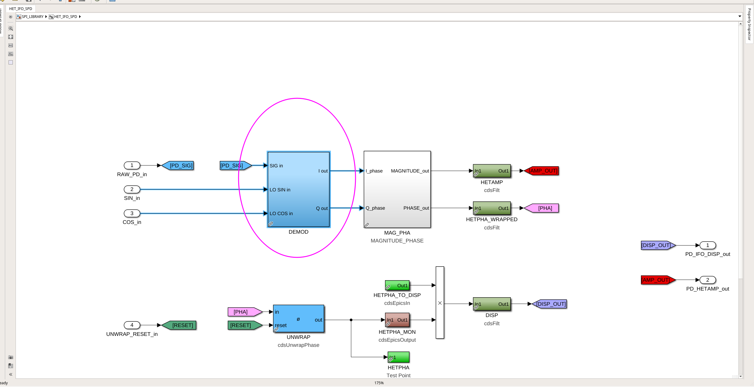
Per Sina's suggestion I checked the model and the demodulation calculation was:
Q = S(w) * cos(w_LO)
I = S(w) * sin(w_LO)
Then both I and Q signals are filtered to yield only the DC component.
The magnitude and phase of the interferometric measurement are calculated as:
|A_het| = Q_DC^2 + I_DC^2
angle(A_het) = tan^-1(Q_DC/I_DC)
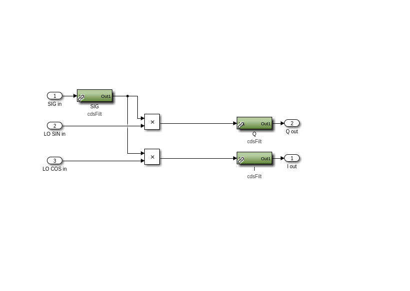
This is incorrect and so we have now put in a change in the model so that the 'DEMOD' block in SPI_LIBRARY/HET_IFO_SPD/DEMOD calculates:
Q = S(w) * sin(w_LO)
I = S(w) * cos(w_LO)
All changes were saved and committed to the svn. The DEMOD block was a standard CDS library part so I needed to create a new version of this saved as 'hetdemod2.mdl' and use this in the SPI_LIBRARY instead. The part is saved in userapps/spi/common/models.
This is what this new block looks like. Erik also doubled checked that the arctan2 function used to get the phase is done as we expect.
After putting in the new model changes (alog #91548) the I and Q are swapped so this changes the phase but has no effect on the amplitude. So we still have another problem.
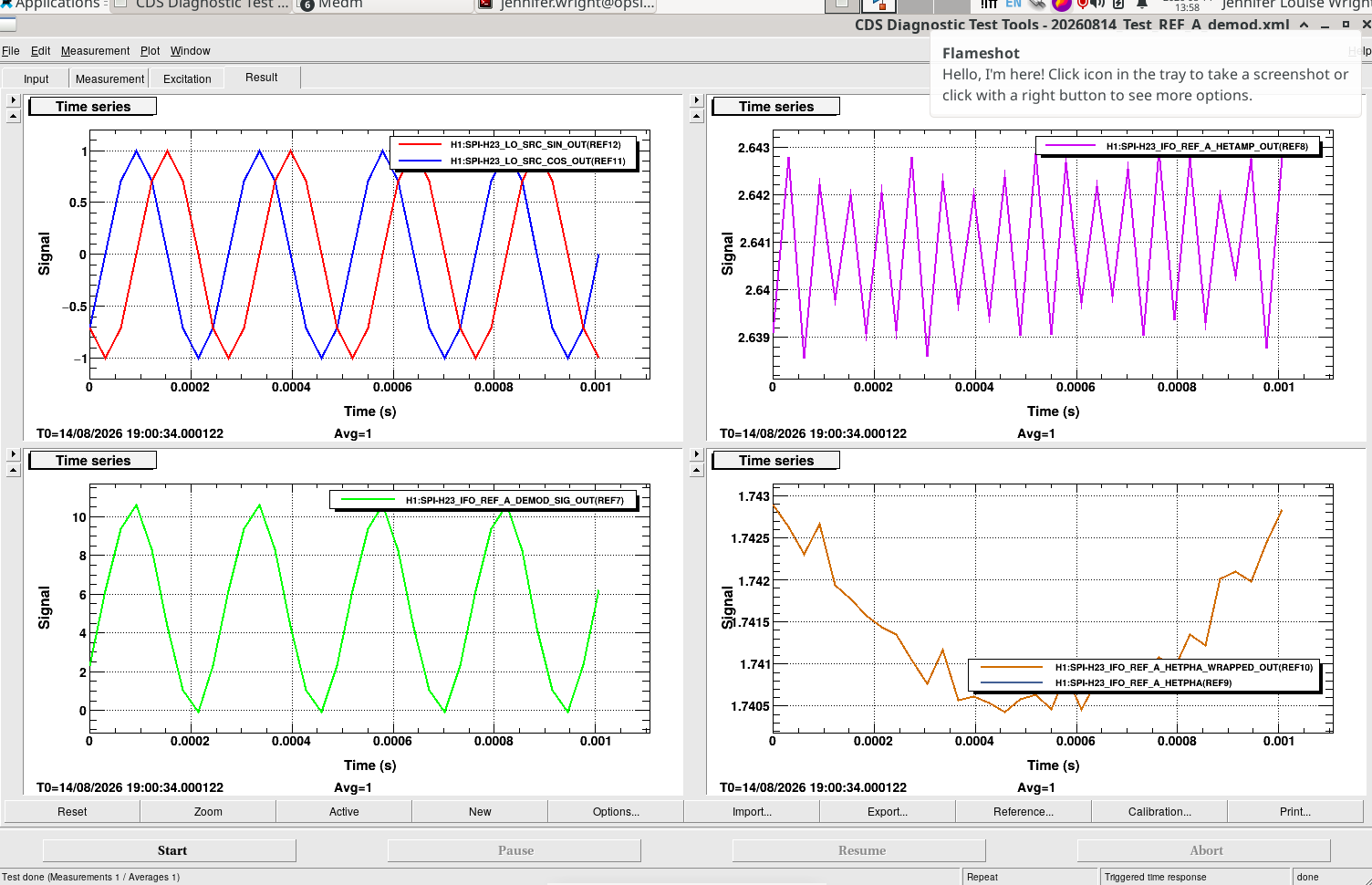
I did another measurement of REF IFO PD A. The demodulated I and Q channels are shown on the bottom right plot. Since I is roughly 0.7 and Q is roughly -2.5 we expect to calculate the values of 2.6V for the amplitude (bottom left plot) and -1.3 radians for the phase (top right plot) for the given I and Q values.
However looking at the raw signal (middle left plot) the peak to peak amplitude should be 10 and so there must be something else wrong with the way we are doing the demodulation.