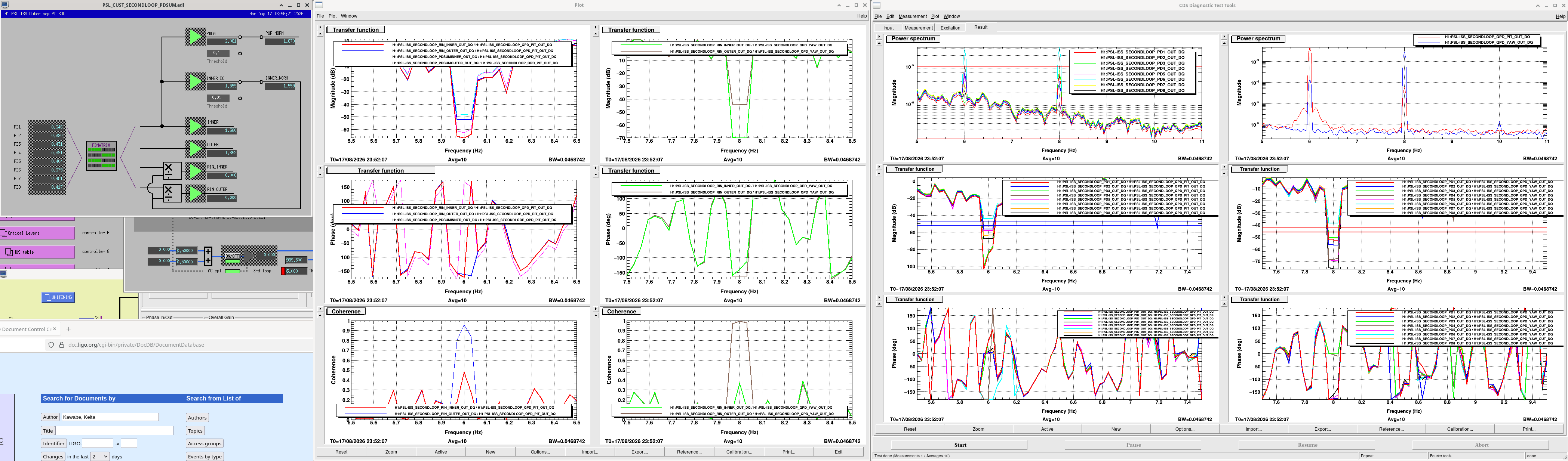
Just to confirm that there's nothing grossly wrong with the beam coming into PSL ISS 2nd loop array, I tried to minimize the jitter coupling from IM3 dither to PDSUM_INNER. If there is something terrible, we might have to change the IM2 and IM3 angle again, which will change the input alignment into the IFO, so it makes sense to say that IM2/IM3 are good now. That way, ISS alignment will be truly isolated from the IFO.
I moved two picos for ISS and ended up with the following coupling in RIN/m:
- RIN_INNER: PIT 3.3, YAW 2.3
- RIN_OUTER: PIT 17.5, YAW 43.9.
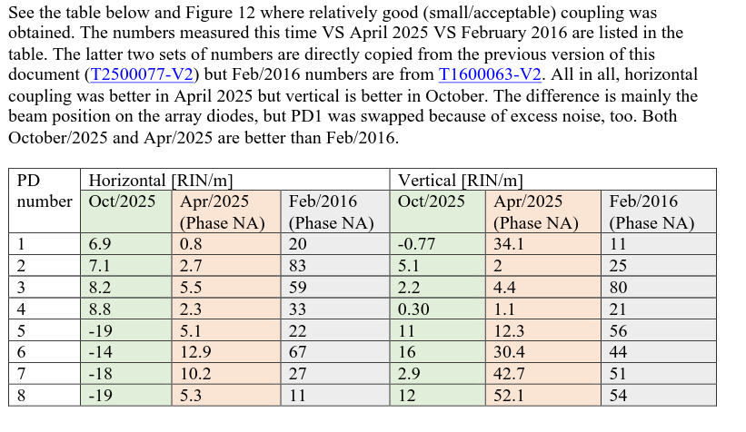
This looks to be consistent with October/2025 measurements in the lab: https://dcc.ligo.org/T2500077-v4, the screenshot of which is attached here as 2025October_T2500077.png. INNER (i.e. PD1/2/3/4) PIT is somewhat worse, INNER_YAW is at least a factor of 3 better. (OUTER_PIT is somewhat better and OUTER_YAW is a factor of 2 worse, but I haven't tried to make OUTER sensor better.)
I went away from the center of the QPD: PIT=-0.603 YAW=-0.295, which corresponds to -84um in PIT and -41um in YAW. This is to say that the displacement is not huge at all. Don't try to center.
The first pico (ch1 for HAM2) was moved from (X,Y)=(0,0) to (569,-476), the second (ch8) from (0,0) to (685, -541).
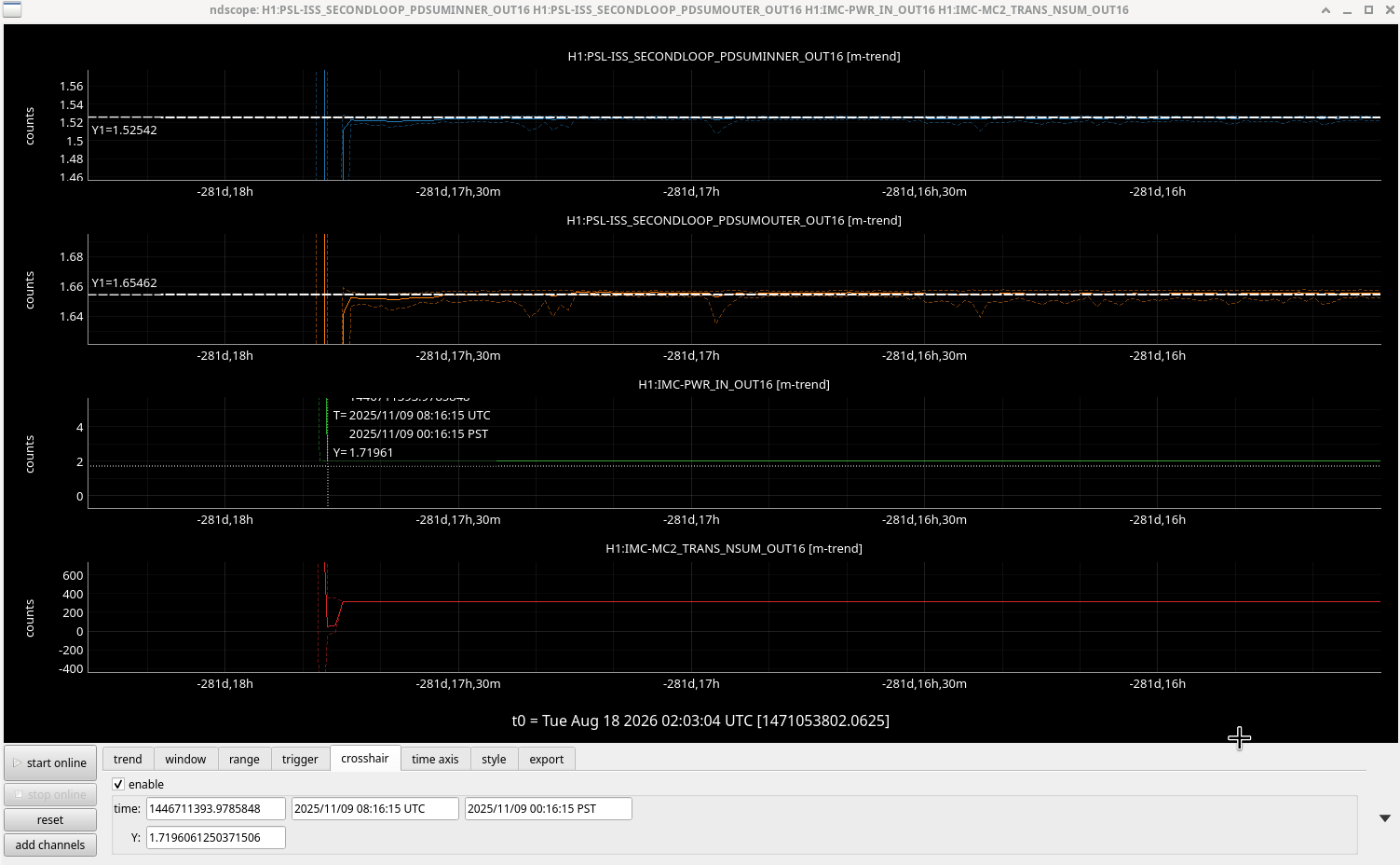
Though individual diode outputs are all different from O4 days because of different alignment, PDSUMINNER and PDSUMOUTER are the same as in O4 (compare ISSpath_align_20260817.png with ISS_INNER_and_OUTER_in_O4.png).
I didn't make a huge scan so I don't know how far the beam is from the edge of the diodes, but this already looks OK to me. If needed we can search for a better spot position further without changing IM2/3.
What was done:
- Dither IM3 in PIT (6Hz, 40 counts into H1:SUS-IM3_M1_OPTICALIGN_P_EXC) and YAW (8Hz, 40 counts).
- Look at the peak height in each PD like H1:PSL-ISS_SECONDLOOP_PD1_OUT_DQ.
- Move two picos. At first maximize the DC of PDs, then tune further to roughly minimize the dither peaks in the INNER group (I cannot minimize both INNER and OUTER at the same time).
- Measure TF from ISS 2nd Loop QPD P and Y output to RIN_INNER and RIN_OUTER.
- QPD output is 7.2 counts/mm for the displacement of the beam along the QPD surface, assuming that the beam size in chamber is the same as the beam we used in the lab (see https://dcc.ligo.org/T2500077).
- disp_[P|Y] = QPD_[P|Y] / 7200[ct/m].
- Coupling for [P|Y] in RIN/m = H1:PSL-ISS_SECONDLOOP_RIN/disp_[P|Y] = 7200[ct/m]*H1:PSL-ISS_SECONDLOOP_RIN/QPD_[P|Y] .
DTT template and my detailed memo of what was done are available in /ligo/home/keita.kawabe/ISS2ndAnd3rdLoop/ISS2ndLoopAlignment