
[Jim W., Shoshana A., Michael R., Huyen P.]
0. Since HAM3 ISI has been updated with new CPS sensors (with fine vertical CPS), Jim updated new symetrization filters for the actuators using the ISI commissioning scripts.
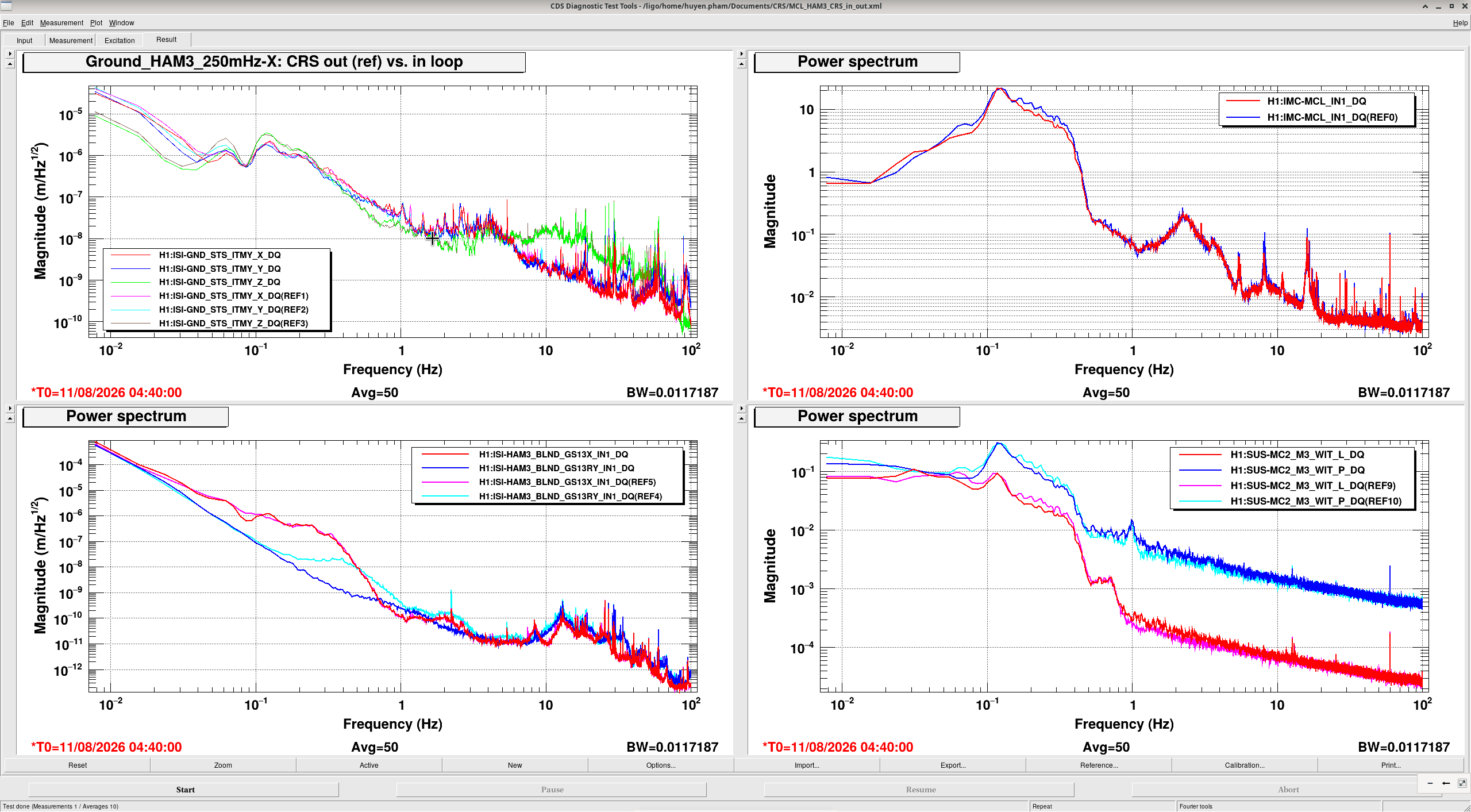
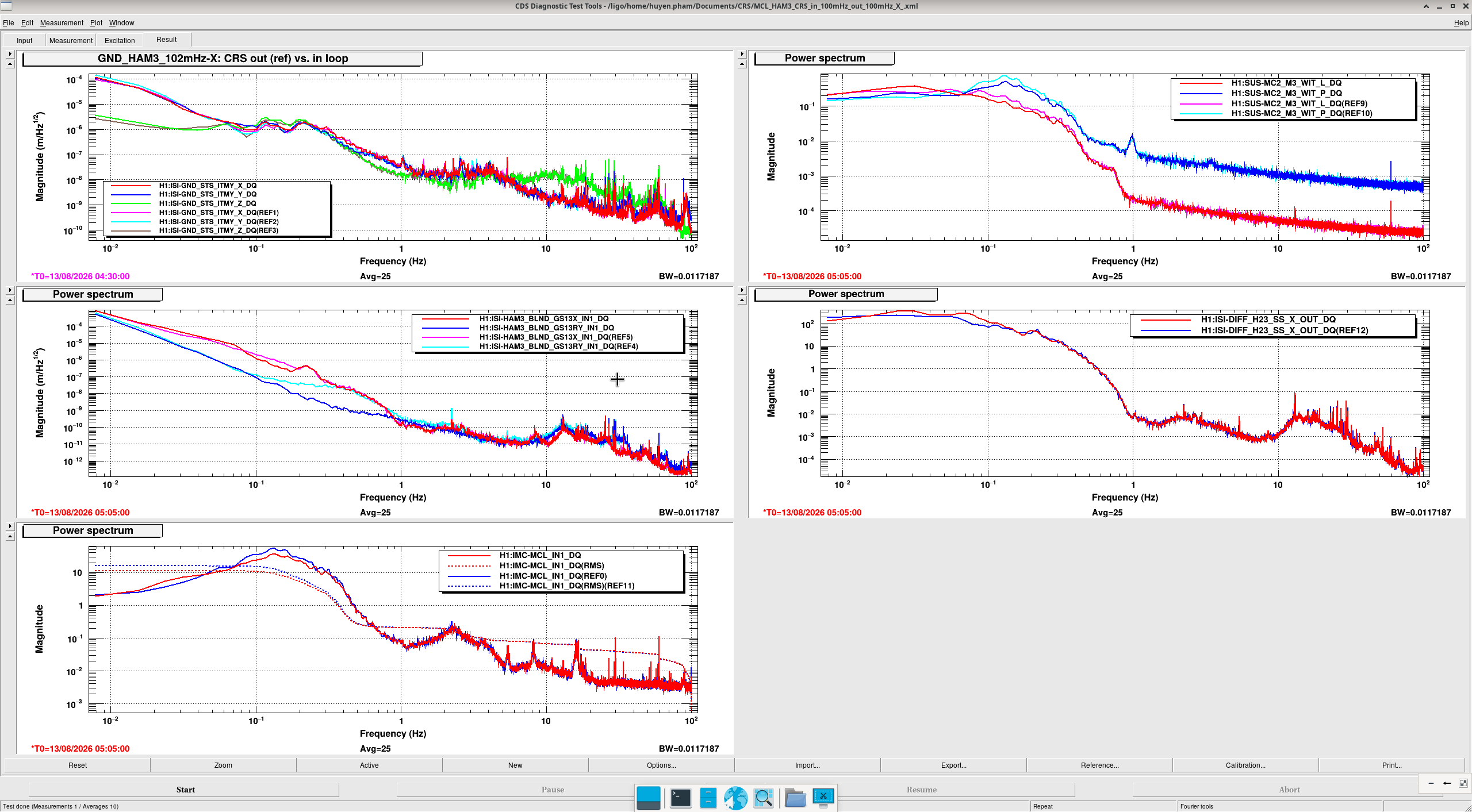
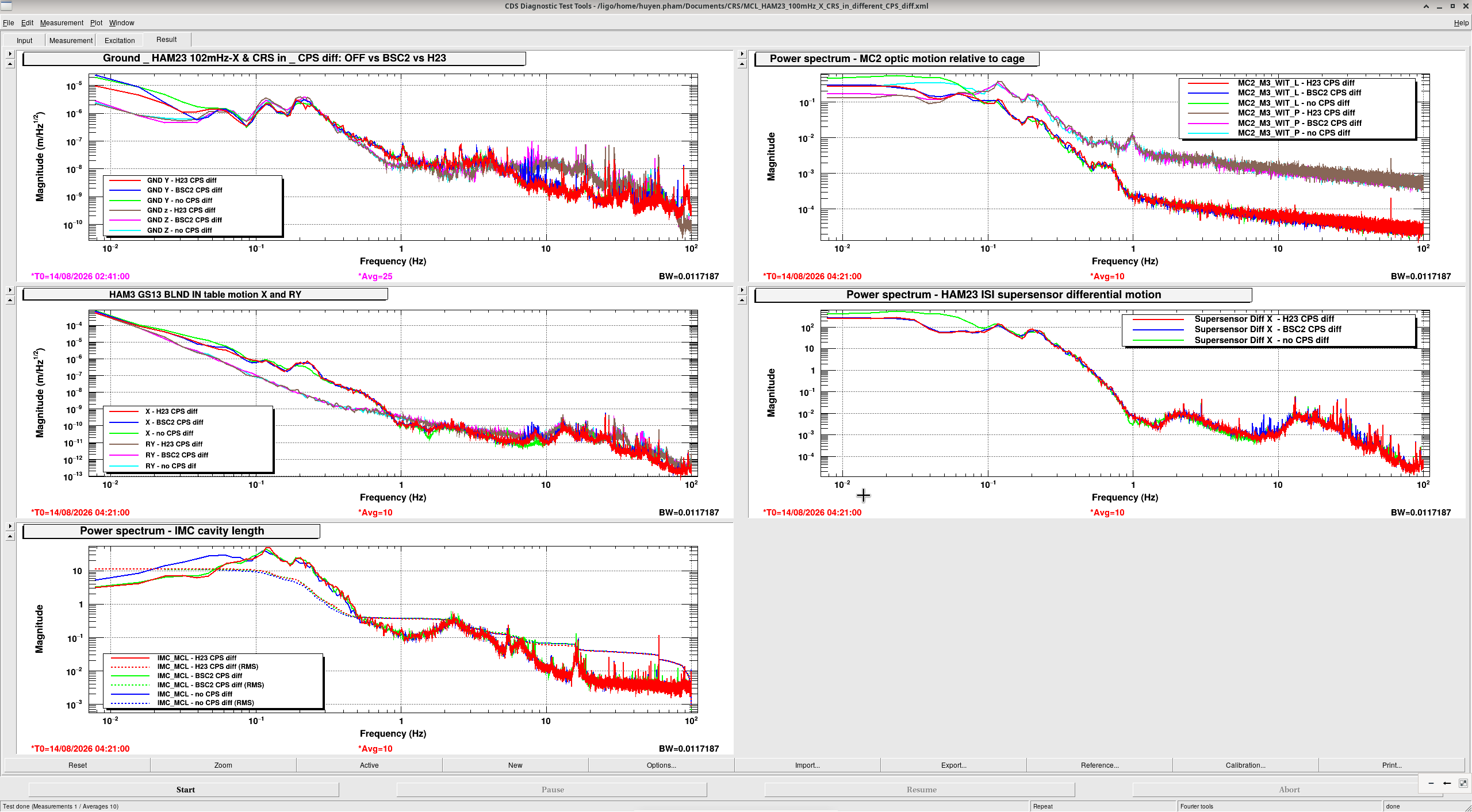
1. We have been testing CRS in/out of loop looking at IMC length (mostly during night time with IMC locked at 2W). The wind condition has been relatively quite so far for these tests. We can repeat in higher wind (ground tilt) condition.
| Time | HAM2 blend X | HAM3 blend X | HAM3 blend RY | CPS diff config | Results |
|
08/10 |
250mHz |
250mHz |
'many notches' - CRS out of loop 30mHz - CRS in loop |
following BSC2 |
CRS in-loop improved ISI RY down to GS13 noise Not much improvement in ISI X MCL see minimal improvement below 0.4Hz |
|
08/11 |
250mHz |
250mHz 102mHz |
'many notches' - CRS out of loop 30mHz - CRS in loop |
following BSC2 |
CRS in loop + 102mHz blend X - see improvement in X Know that this is mainly from blend push, not CRS MCL see x3 improvement below 0.4Hz |
|
08/12 |
250mHz | 102mHz |
many notches' - CRS out of loop 30mHz - CRS in loop |
following BSC2 |
Testing CRS effect on cavity length motion. Confirm that the improvement in ISI X and MCL saw in thelast test mainly coming from blend push. |
|
08/13 |
102mHz | 102mHz | 30mHz - CRS in loop |
no CPS diff Following BSC2 HAM23 CPS diff |
HAM23 CPS diff or BSC2 BSC diff improve upto x4 below 0.1Hz |
We will try lower blend, e.g. 45mHz.
2. With CRS out of loop, we compared tilt spectra for CPS, GS13, and CRS. Without the proper capacitive damping, the OFFLINE/DAMPED stage rings up the CRS, making low frequency signal worse. Under ISOLATED state, the CRS can be damped, and CRS matches GS13 between 0.2Hz - 1 Hz. This test has been done at MIT, see alog 12136.
3. I also did make a different set of GS13 vertical symmetrization filters using global Z comb drive scripts from Brian, see last figure. The filter file is living under /ligo/svncommon/SeiSVN/seismic/Common/Documents/T2300404_HAM_symmetrization/ham3_fine_cps_and_crs/. We will test this later.



3 again. The symmetrization filters: The new comb drive filters are suprisingly very similar to the old comb drive ones, while the l2l drive filters old vs new filters are distinctly diferrent - see figure 1. We should test the new l2l.
4. Remeasure CRS resonance (tilt to tilt TF): I used the same ry_exc2.txt awggui template but to get the same drive amplitude, I have to up the gain to 7e3 instead of 2e3 as last time this was measured (alog 91179). After fitting, the result shows that the resonance moved very slightly, see figure 2. The delta (distance between CoM and Center of Rotation) moved from 11µm to 10µm, and the natural frequency moved from 22.22mHz to 22.11mHz. I updated new sensor inversion anyway in both theta filter bank and the 30mHz bandpass of the blend, see figure 3. I also did two excitations with low gain that might be good for SPI commissioning. The excitation time shows below (no CRS damping nor CRS in-loop for these).
|
Date |
Time start |
Duration |
Gain |
Note |
|
08/17/2026 PDT |
20:57 |
30min |
8e3 - 1e4 |
ISI isolated. SPI QPDA pit and yaw under 0.3 |
|
08/18/2026 PDT |
08:20 |
1hr |
2e3 |
ISI damped. SPI QPDA pit and yaw under 0.3 |
|
08/18/2026 PDT |
20:35 |
1.5hrs |
8e3 |
ISI damped |
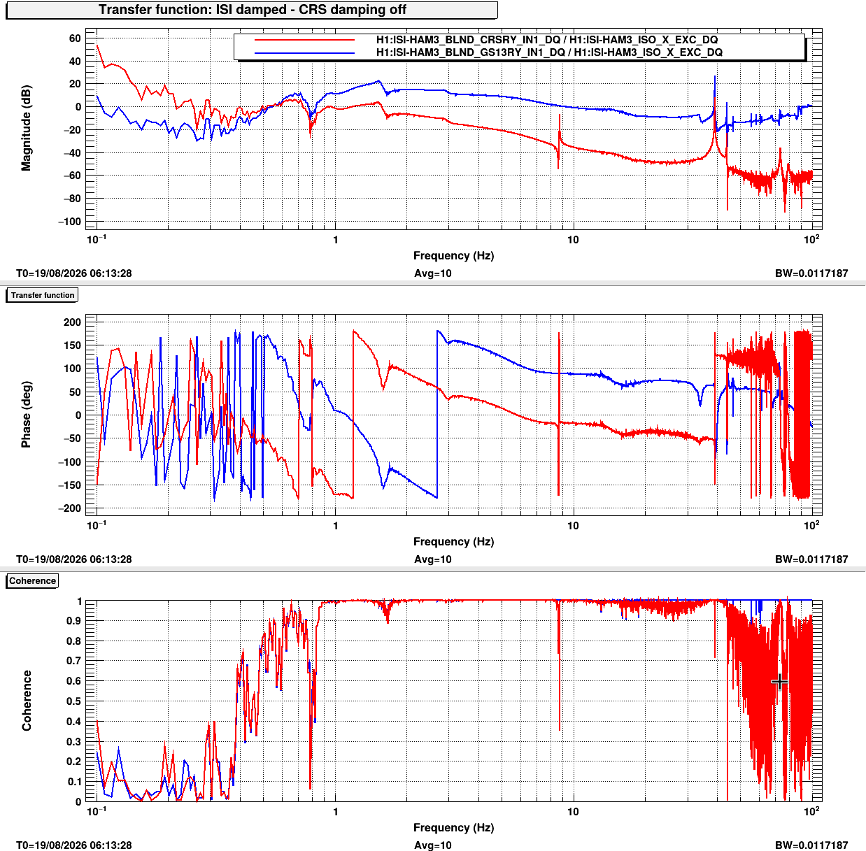
5. Horizontal to tilt coupling above 1Hz: An excitation in X direction was done via ISO_X path, see figure 4, and the dtt is saved in /ligo/svncommon/SeiSVN/seismic/HAM-ISI/H1/HAM3/CRS/Templates/dtt/HAM3_CRS_X_to_RY_coupling_1-100Hz_20260818.xml. The coupling starts to subside as above 1.5Hz. This length drive also excited the torsional mode of the CRS around 8.7Hz.


"3 again. ... We should test the new l2l."
No, we should abandon the Local 2 Local measurements. It is useful to see if sensors are alive and working, but not useful for precision calibration. The CPS and GS-13 are in different places, so they respond differently to RX and RY motion. When we drive 1 actuator, we impose lots of RX and RY motion. Trying to make the local GS-13 and local CPS match each other is a mistake, because it would be extrememly surprising if they were seeing the same signal. When the payload changes, the (RX or RY)/Z motion changes is a frequency dependent way, so the L2L measurements are likely to change.
The comb drive tries to fix this. The excitation is a mostly vertical signal, and then the code does a virtual repositioning of the CPSs to the GS-13 location. Seeing that the blue curves match so well is reassuring.