J. Kissel, J. Wright

Jennie and Marc did some dark noise investigations yesterday afternoon, found grounding issues, but then reverted the temporary configuration that improved the situation.
However, this morning, mis-reading their aLOG thinking that the solution was still in place, I re-took new ASDs excited to see QPDA fixed.
Even though their temporary solution has been reverted, QPDA still seems to be fixed.

So -- here's some excellent, final answer plots for pitch and yaw, comparing HAM2 and HAM3 rotation against their local sensors.

PITCH
    - Now, as expected, the whitened ADC noise QPDA aka ISIK's HAM3 sensor is the factor of ~5x larger where the QPD is limited by ADC noise above 0.5 Hz, and it has the same inverse-whitening-filter shape as QPDB.
    - Encouragingly, the QPDA ISIK optical lever PIT signal matches the HAM3 CRS RY signal below 0.5 Hz -- so this QPD will be at least a little bit useful!
    - The noise floor of the QPDA ISIK optical lever PIT signal is better than the CRS above ~2 Hz, though the actual platform motion (as reported by the GS13s) is still much lower than that.

    Very interesting science --
    - The improvement in platform motion of HAM3 from blending in the CRS is corroborated with the ISIK optical lever signal below 0.5 Hz.
    - The QPDB measure of HAM2 shows that there's a lot more physical motion in PIT in the 1 to 10 Hz region than is reported by the in-loop GS13s. In that region, the QPD's signal is a factor of 10 above the noise floor, so I'm pretty sure this is real signal.

YAW
    - Again, the two SPI QPDs noise floor now makes sense, with the QPDB (on HAM3) measurement of HAM2 (ISIJ) noise floor being a factor of ~5x better than the QPDA (on HAM2) measurement of HAM3 (ISIK).
    - Thus, the SPI OL YAW measure of HAM2 agrees with the local HAM2 sensors up to ~0.8 Hz, but the OL YAW measure of HAM3 only agrees up to 0.5 Hz.


Measurement time: 2026-09-04 16:47 UTC. I took 25 averages with a 0.01 Hz frequency resolution. Hanning window with 50% overlap.

ISIs were isolated, IMC was locked, still no IFO tho. sensor correction was ON in the nominal WINDY configuration. No earthquakes. CRS is blended in with ISI HAM3.
Spots centered, nominal sum voltage.

DTT Calibration of traces beyond what's done in the front-end is what's quoted in LHO:91809, namely -- just a conversion of nanoradians to radians for sensors already in displacement, and converting the GS13s from inertial sensor units asymptoting to 1 [nm/s] into displacement by inverting the ideal 1 Hz pendulum response.


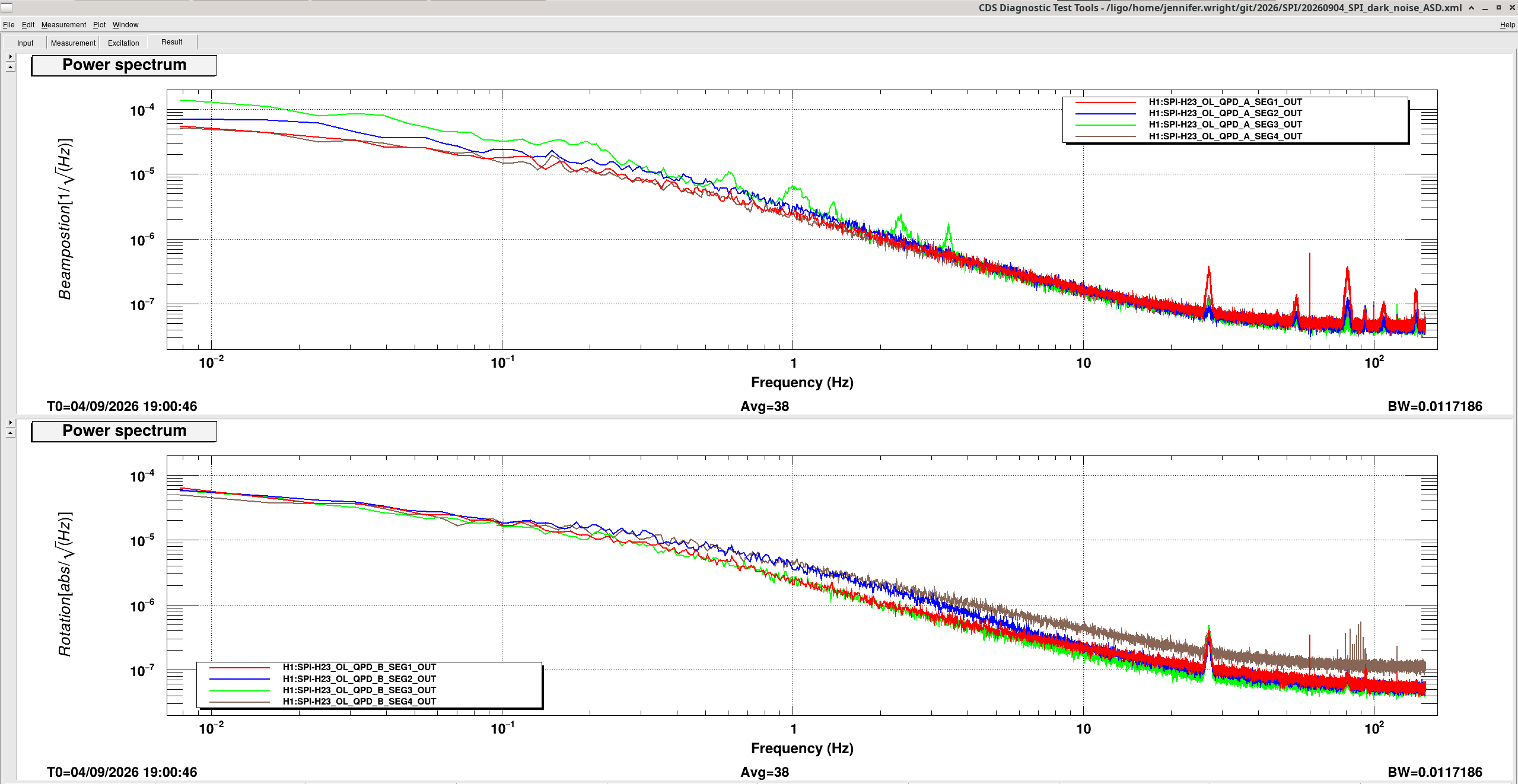
Summary: The excess noise on the ground for both QPDA and B seems to come and go.
I re-measured the dark current on QPD A and B to figure out why Jeff's measurements show that the QPD A spectrum no longer looks wrong. Following the prcoedure we followed for the dark noise measurement of the QPDs in LHO alog #91772.
I shuttered the SPI laser and put an offset of 11000 on QPDA and 12400 on QPD B to give a fake signals on each quadrant that matches the voltage on each QPD when the laser is unshuttered.
Then I measured an ASD of all 8 QPD quadrants. There was a glitch so I switched to doing an accumulative measaurement. You can see that both QPDs have some noisier quadrants.
I also took a time series and right before started the measurement above you can see a glitch in the level of each quadrant.
Marc and I are going to do more ground loop checks. After talking with Jeff each QPD is meant to use the TIA ground (rack ground) as a reference but if there is some grounding problem in the chamber at the QPD itself maybe we are getting some intermittent signal pick-up on this ground loop.

Marc and I checked QPD B and this is also grounded to chamber ground through pin 13. Each other pin is isolated. We confirmed pin 13 is also connected to the chassis ground.
We did not check the third TIA chassis (variant 3) as this gets its input signals from TIA chassis 2.