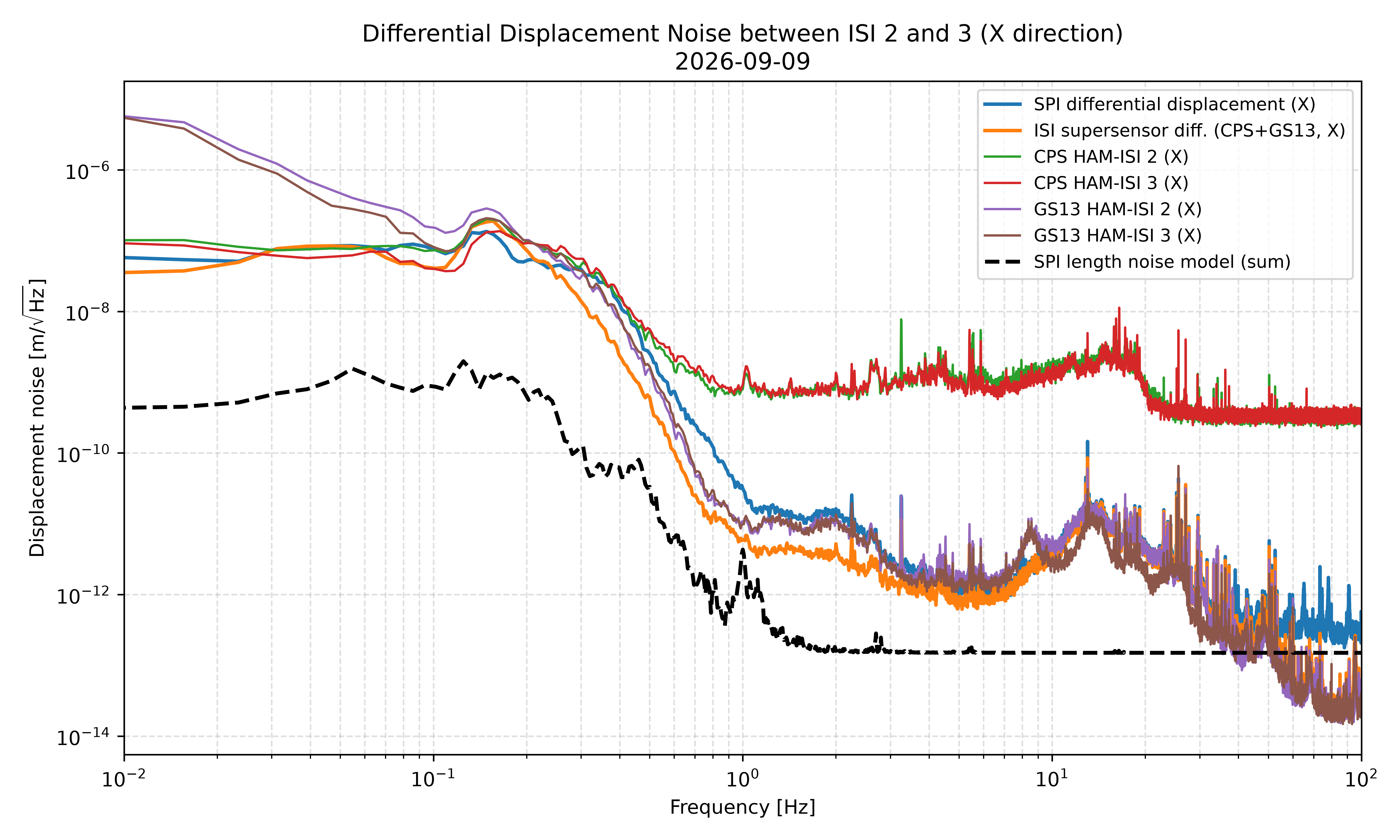
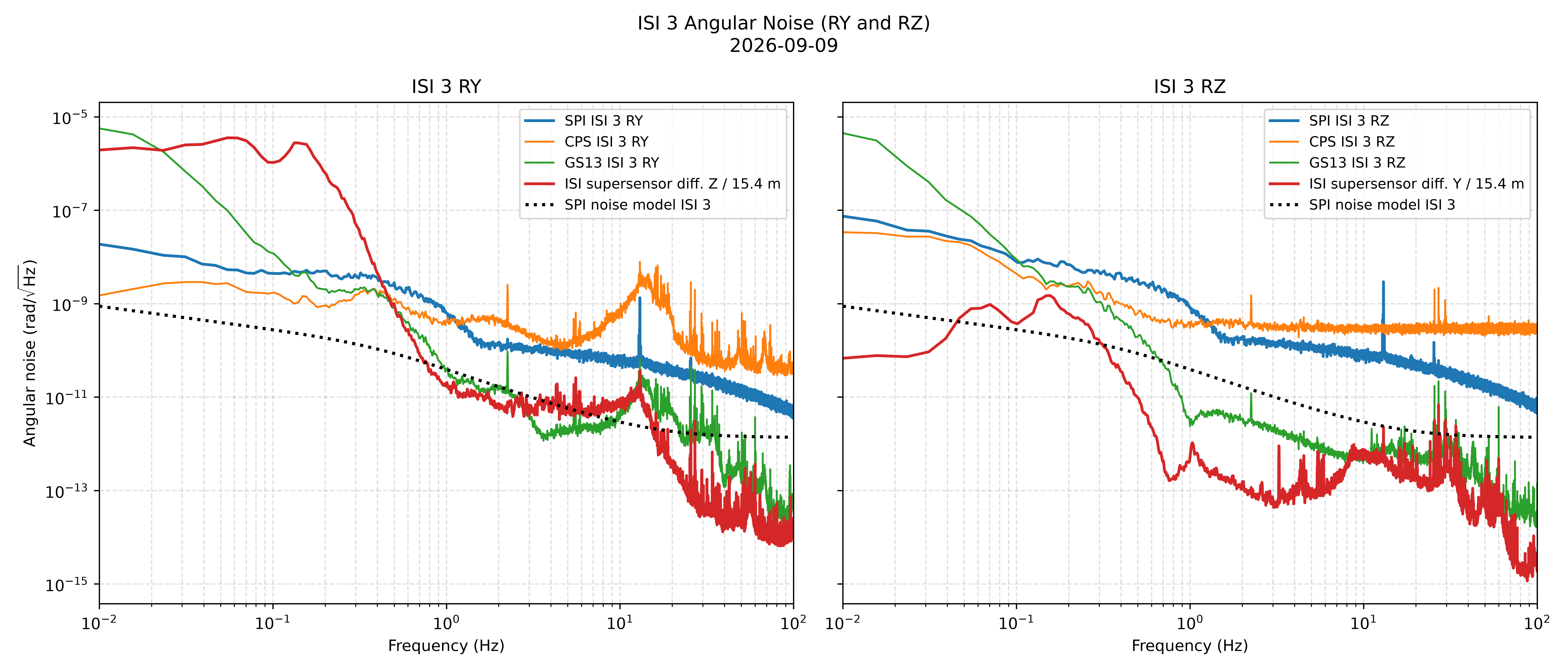
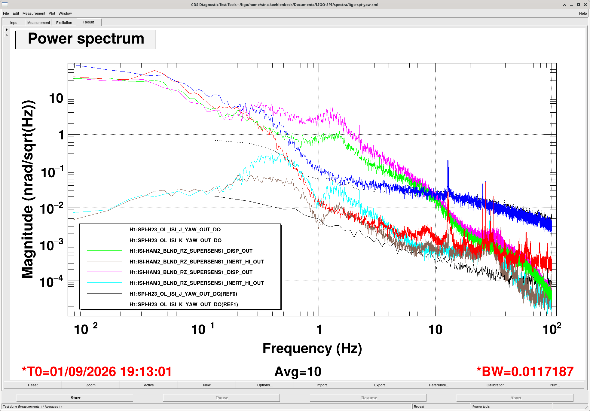
After the angle calibrations were applied to the SPI readout channels, I grabbed some data to check whether the SPI is roughly agreeing with the ISI sensors. I used the supersensor OUT channels for the ISI sensors (these are the signals behind the blending filters, before the summation for the blended supersensor). Screenshots from diaggui are attached.
For the differential X degree of freedom (SPI length), the visual agreement is remarkably good.
The optical lever (angle) measurements are harder to interpret. First of all, QPD A has an as-yet-unresolved noise issue, which Jennie is currently investigating. Aside from this, the results look very encouraging, since the CPS and GS13 at least somewhat agree with the SPI.
These spectra should be regarded as a first result, but not yet final. We will post a better analysis once the error has been resolved.
Note: If anyone has suggestions for which sensor channels would provide a better/more appropriate comparison than the supersensor OUT channels used here, please comment, your input is welcome.
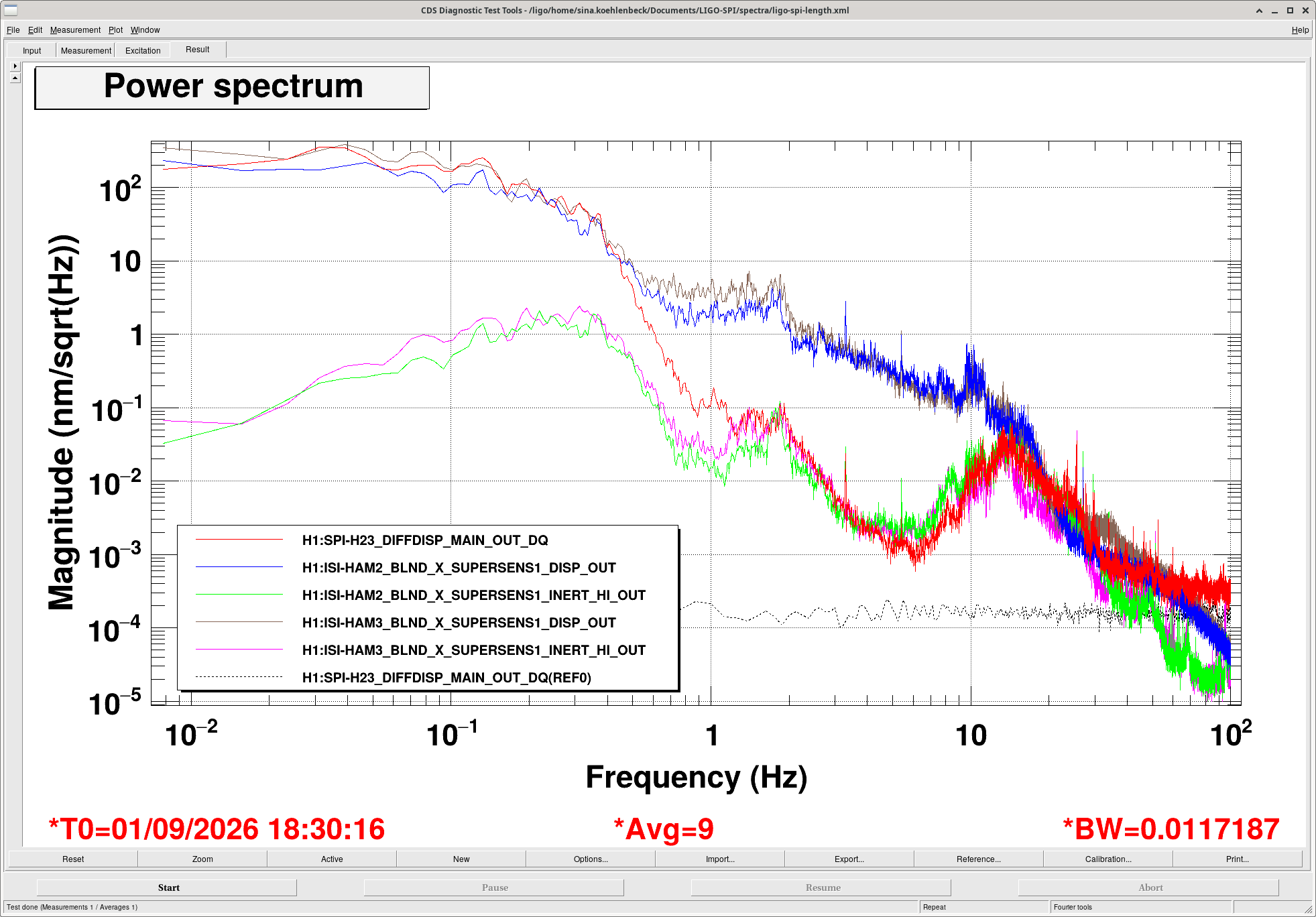
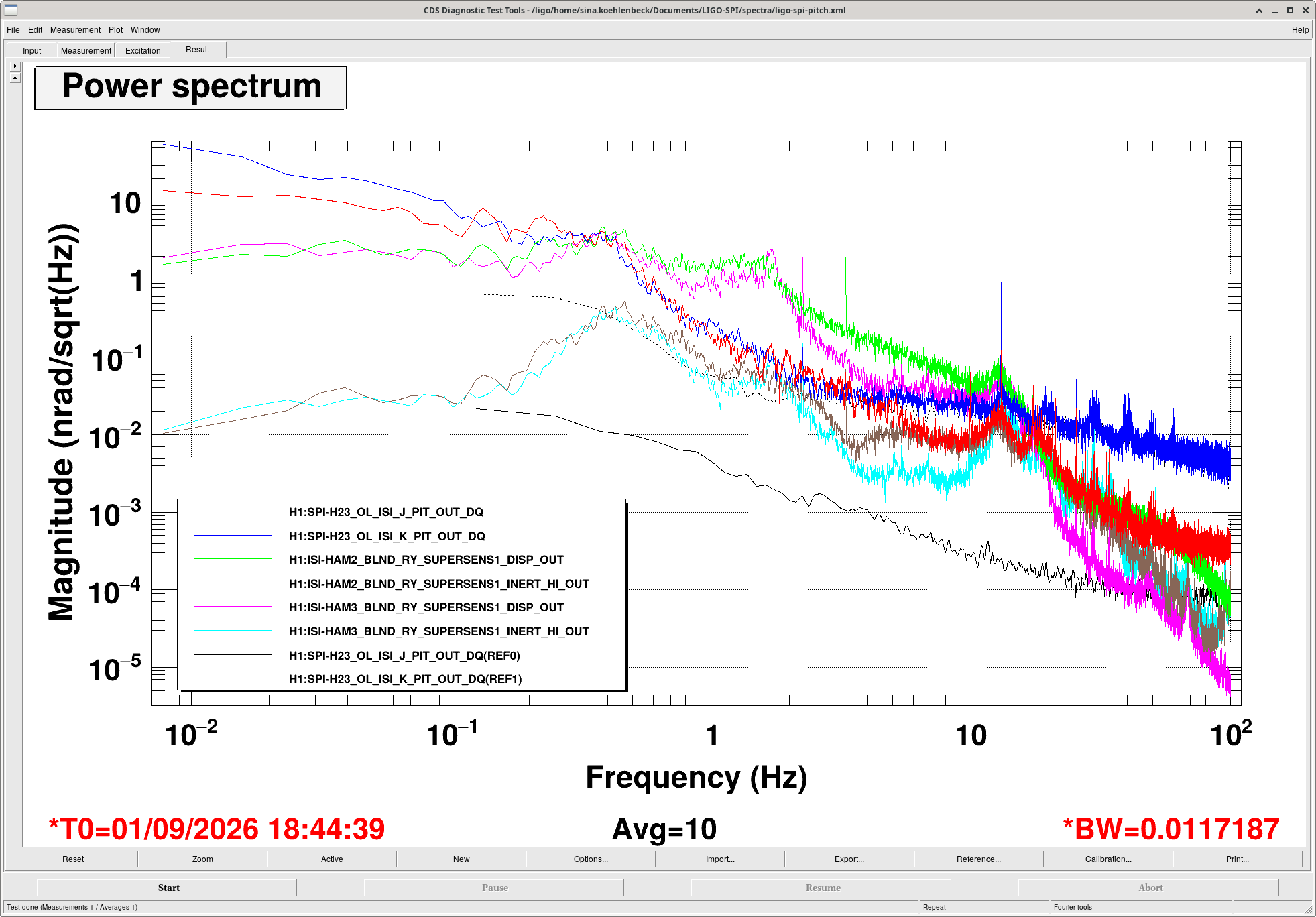
Brian pointed me to a set of new data channels that provide calibrated outputs directly in displacement units. Using these channels, I acquired spectra with DTT at UTC 2026-09-09 12:00:00 (BW = 0.01 Hz, 30 averages) and generated the plots that follow
Channels plotted — Angular (RY / Pitch):
Optical lever pitch signals (angular, rad/√Hz):
H1:SPI-H23_OL_ISI_J_PIT_OUT_DQ(ISI 2) — Optical lever ISI J pitch angleH1:SPI-H23_OL_ISI_K_PIT_OUT_DQ(ISI 3) — Optical lever ISI K pitch angle
ISI blend / CPS RY signals (ISI RY witness channels):
H1:ISI-HAM2_BLND_CPSRY_IN1_DQ(ISI 2) — HAM2 blended CPS RY inputH1:ISI-HAM3_BLND_CPSRY_IN1_DQ(ISI 3) — HAM3 blended CPS RY input
ISI calibrated Cartesian RY signals (rad/√Hz):
H1:ISI-HAM2_CAL_CART_RY_OUT_DQ(ISI 2) — HAM2 calibrated Cartesian RY outputH1:ISI-HAM3_CAL_CART_RY_OUT_DQ(ISI 3) — HAM3 calibrated Cartesian RY output
Differential Z displacement channel (converted to rad/√Hz):
H1:ISI-DIFF_H23_SS_Z_OUT_DQ— Differential H23 SS_Z displacement. Given in nm/√Hz; converted to m/√Hz, then divided by the arm length (15.4 m) to yield rad/√Hz.
Channels plotted — Differential X motion (displacement):
H1:SPI-H23_DIFFDISP_MAIN_OUT_DQ— SPI H23 main differential displacementH1:ISI-DIFF_H23_SS_X_OUT_DQ— Differential H23 SS_X (CPS + GS13 supersensor)H1:ISI-HAM2_BLND_CPSX_IN1_DQ(ISI 2) — HAM2 blended CPS X inputH1:ISI-HAM3_BLND_CPSX_IN1_DQ(ISI 3) — HAM3 blended CPS X inputH1:ISI-HAM2_CAL_CART_X_OUT_DQ(ISI 2) — HAM2 calibrated Cartesian X output (GS13)H1:ISI-HAM3_CAL_CART_X_OUT_DQ(ISI 3) — HAM3 calibrated Cartesian X output (GS13)
All scaled by nm_to_m (nm/√Hz → m/√Hz).
Unit conversions:
- OL_ISI_J_PIT and OL_ISI_K_PIT plotted in rad/√Hz
- SS_Z converted from nm/√Hz to rad/√Hz by dividing by a length of 15.4 m
- Differential X-motion channels scaled from nm/√Hz to m/√Hz (nm_to_m factor)
- Angular y-axis units in rad/√Hz; displacement y-axis units in m/√Hz