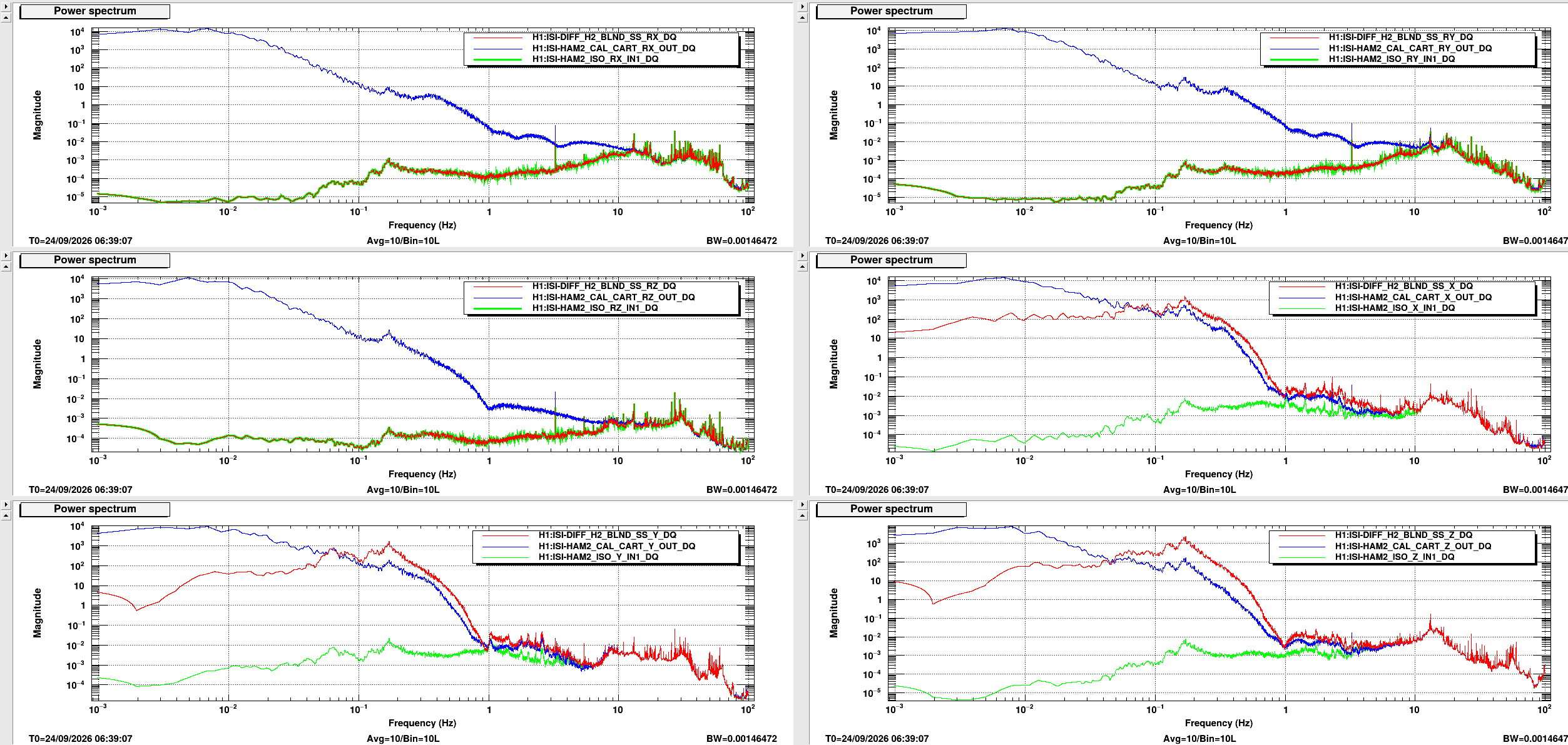
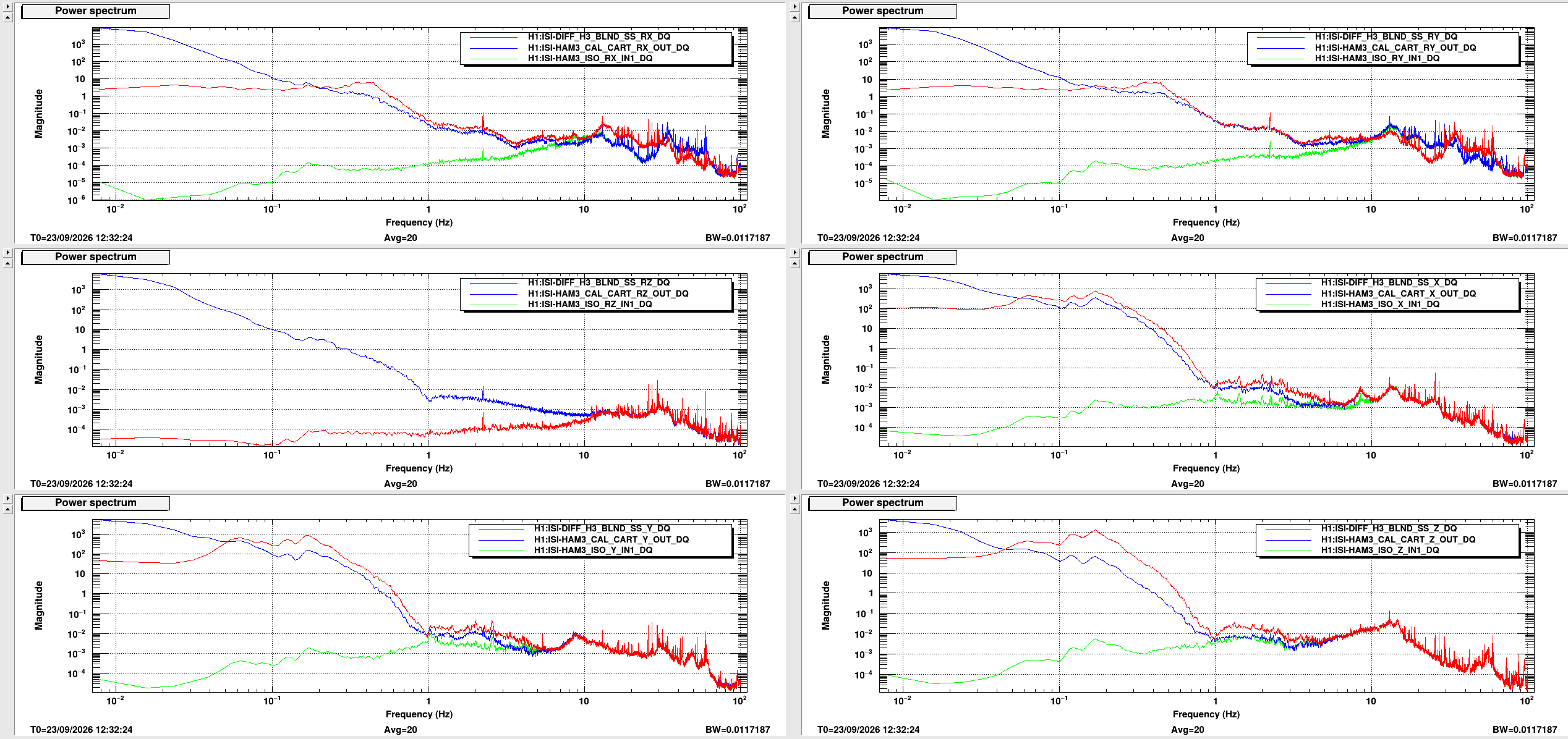
We have started looking at the synthetic supersensors we created in seiproc for SPI commissioning and there are some things going on there I don't understand. For the 2 attached plots I look at 3 different versions of the table motion or loop error point, some calibrated GS13 CAL channels, the synthetic supersensors and the ISO loop inputs. For each subplot, red is the supersensor, blue is CAL CART GS13s, and green is the ISO in, first image is HAM2, second is HAM3, they weren't taken at the same time, so the spectra don't look exactly the same. I (probably naively) would expected all of these too look the same, with a caveat about sensor correction for the supersensor channels, the cps used there is before the sum with sensor correction, so the GS13 CAL and supersensor not matching between .1 and a few hz for X,Y and Z is because of that. What I (and I think Brian and Jeff) don't understand is why the ISO IN channels don't match. The input to the iso loops should just be the sum of the blended cps +senscor and gs13s. The blend filters I put in seiproc to construct the synthetic supersensor are the same ones we run nominally on the ISI. For the rotational degrees of freedom these should be the easiest to understand, but RX & RY for HAM2 and HAM3 are very different. Not sure what is going on. I had found one case of wrong sensors connected to filters in seiproc for HAM2 Z, but that has been fixed.
I have checked the signal routing out of the ISI master blocks to ipc senders to ipc receivers in seiproc and down to filter modules that generated the supersensors and haven't found any more errors, but it's a lot to look through. I have also spot checked that the right filters are installed in a number of places where supersensors don't look right, and have not found any errors so far there, either. I will try to keep looking. One of the next things I will do is read all the filters in matlab and plot them there, to make sure that all the filters are right.
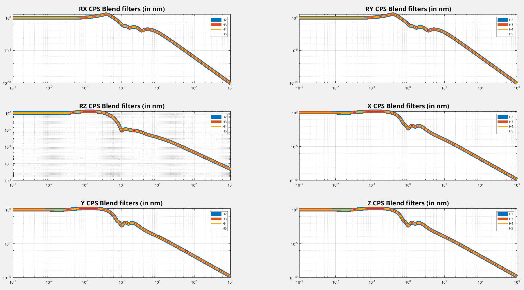
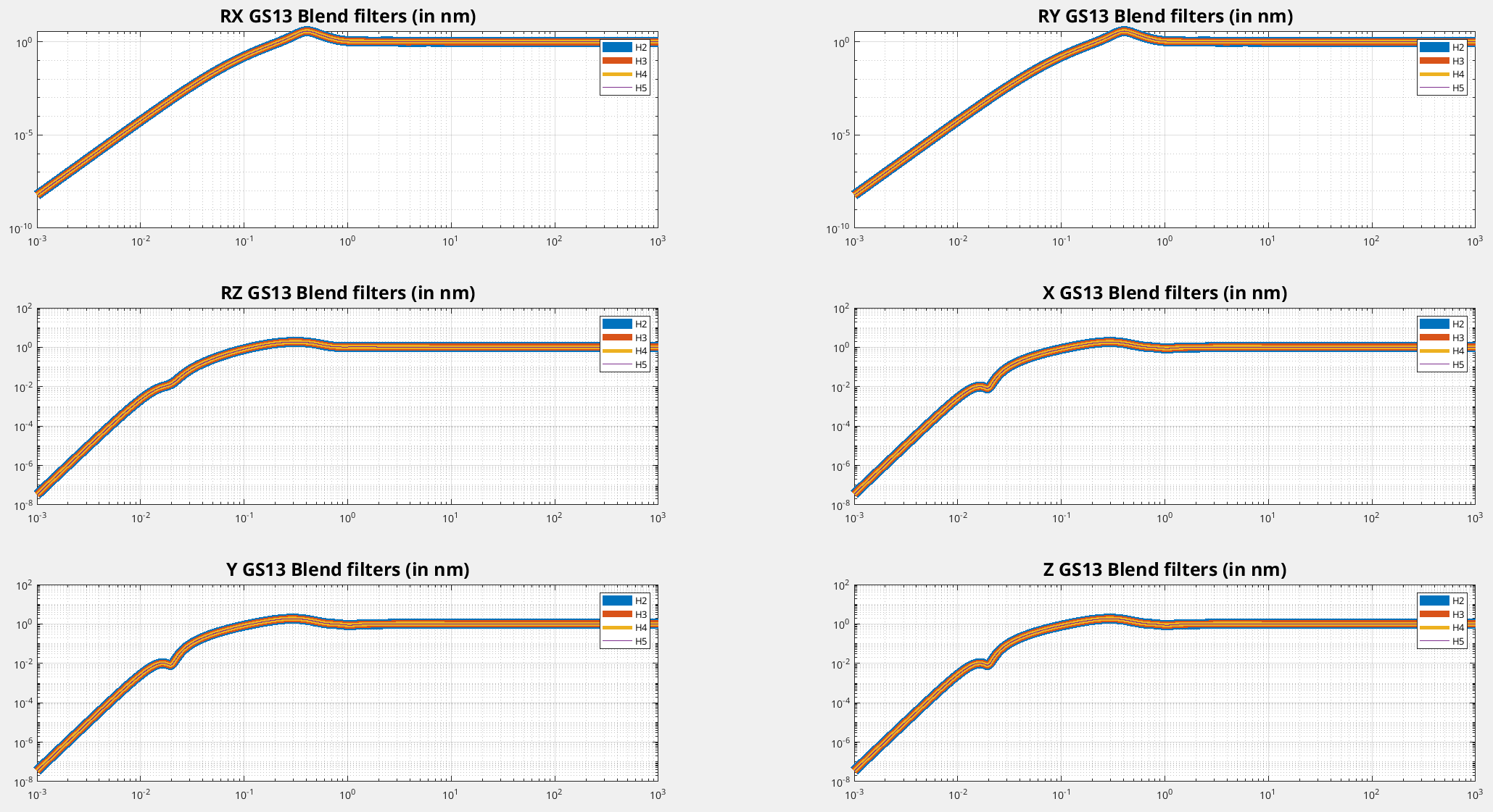
I just checked the blend filters. As far as I can tell, all of the blends loaded into seiproc for these channels are correct.
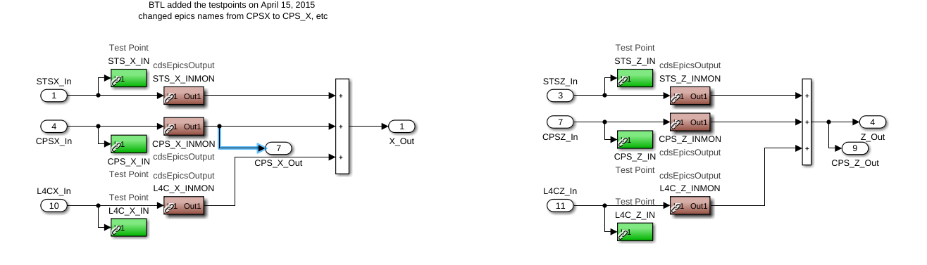
To remove the confusion caused by the sensor correction, we will change the pick off point for the cps one that includes the sensor correction signal. This will only matter for the X,Y and Z dofs. Attached screenshot shows the change, the X pickoff on the left is the current before sc sum, Z on the right is the new pickoff point downstream of the sc sum.
I think this is probably an issue of loops limited by sensor noise. I just did a quick check on the platform at Stanford, and this shows up very clearly
(Tech Demo is fully isolated, passive measurement with the 0p6 blend on stage 2, looking at the X DOF. No sens corr from the ground)
My CPS sensors are not as good as the aLIGO versions.
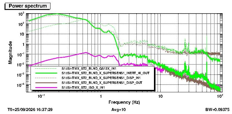
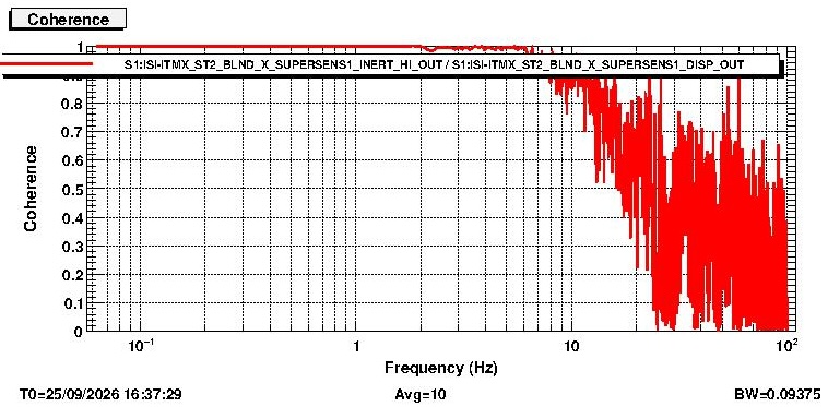
2 plots, first with various signals, second with some coherence
Story: figure 1: Look at the inputs and outputs of the CPS and GS13 signals in the blend being used (blend #1) . The filtering looks as expected, the CPS gets a low pass (brown dashed to brown solid), and the GS13 gets a high-pass and a calibration conversion from velocity sensor to disp (ie (flat at 1 nm/sec above 1 Hz, scaling as f^2 from DC to 1 Hz) -> 1 cnt/nm) - green dashed to green solid.
The magenta signal is the sum of these two sensor signals, and the sum is very much below either signal up to about 10 Hz. So - these signals are entirely coherent below 10 Hz, and they cancel. This is likely because each sensor is adding noise, the loop is supressing the in-loop noise by imposing it as motion on the table, and now both sensors see the motion. See T2500279 for math about this.
The second plot shows the coherence between the CPS filter out and the GS-13 filter out. indeed, they are very, very coherent.
--
So - There is sensor noise, big deal. The sensors are limited by their noise and so is the platform. This is not news. You should be wary about believing what in-loop sensors tell you. duh.
BUT - it would be very useful to make a differential signal on HAM2-HAM3 from the onboard sensors to compare with the SPI. We obviously need to think about a reasonable way to do this. Using the supersensor while we drive the tables should be fine because the sensors are not noise limited. During normal operation we should think a bit more...
(sorry for the terrible image quality)