Written by Yuta, posted by Koji, while he is waiting for his ligo.org account:
In order to get the frequency noise from alignment fluctuation better than few Hz, the X arm should be aligned whithin ~0.02 urad. This requirement could be relieved by adjusting the sideband frequency.
[Motivation]
In a low finesse cavity, PDH signal from HOM adds an offset to the locking point of 00 mode. So, if the cavity alignment fluctuates, HOM content fluctuates and it will be converted into the frequency noise. This frequency noise was estimated for the current Xgreen situation.
[Method]
1. Calulate beam translation dx and tilt dtheta from ETM/ITM misalignments using the following formula;
dx=(R2*(R1-L1)*a2+R1*(R2-L2)*a1)/(R1+R2-L)
dtheta=(-R2*a2+R1*a1)/(R1+R2-L)
where
L1=L*(L-R1)/(2*L-R2-R1)
L2=L*(L-R2)/(2*L-R2-R1)
and a1,2,R1,R2,L is ETM misalignment, ITM misalignment, ETM RoC, ITM RoC, and cavity length.
2. Calculate HOM content upto 1st HOM using the following formula;
U00 power = (1-0.5*(dx/w0)**2-0.5*(dtheta/alpha0)**2)**2
U01 power = np.abs(dx/w0+i*dtheta/alpha0)**2
where w0 is the cavity wasit radius and alpha0 is the divergence angle.
Note that this calculation is only valid for small misalignment (dx < w0 and dtheta < alpha0).
3. Find zero crossing point of PDH signal for each mirror misalignment to get the dependance of zero crossing point on mirror misalignment.
4. Calculate derivative of 3. to get the coefficient for alignment induced frequency shift (in Hz/urad).
The parameters I used are the same as the ones listed in alog #9381, except for L=3994.5m (see alog #9386)
[Result]
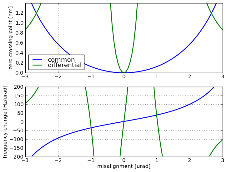
1. zerocrossingPDH_sb24_4MHz.png: Upper plot shows the shift of zero crossing point by cavity misalignment. Lower plot shows the coefficient for alignment induced frequency shift.The blue curve is for ETM/ITM misalignment in v-shape (soft-mode-like). The green curve is for ETM/ITM misalignment in //-shape (hard-mode-like) and is valid only for misalignment < ~0.5 urad.
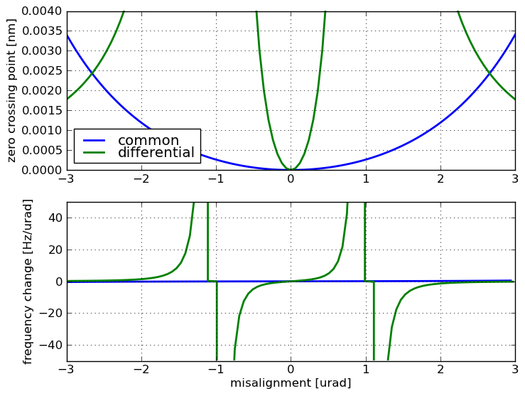
2. zerocrossingPDH_HighFinesse.png: Same plot for ETM transmission of 1%.
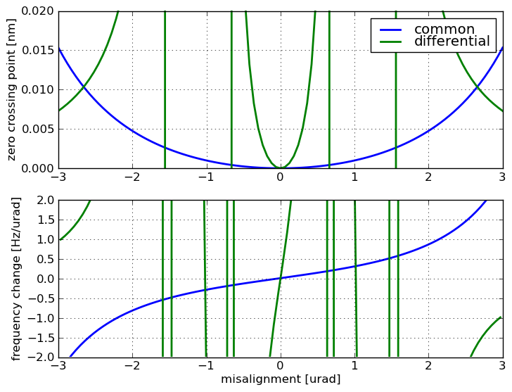
3. zerocrossingPDH_sbadjusted.png: Same plot for the adjusted sideband freqeuncy. The sideband frequency was adjusted to the precision of 1% to get minimum frequency noise (the zero crossing of PDH signal from 01 mode right at the 00 resonance).
[Discussion]
The following discussion is valid when the requirement for the frequency noise is few Hz and mirror angular motion is ~0.1 urad.
1. If we don't change anything, DC misalignment should be better than ~0.02 urad.
2. If we had high finesse cavity, requirement for the DC misalignment was ~0.8 urad.
3. If we can adjust the sideband frequency by 1%, the requirement for DC misalignment is relieved by 2 orders of magnitude.