[Koji Yuta]
On Friday afternoon, an RF amplifier unit with 3f (27/135MHz) diplexer (D1300989) and a 4ch demodulator unit
with 2f (18/90MHz) diplexer mod (E1300899) were installed to R2U27 and R3U8, respectively.
- The RF diplexer amplifier D1300989 S1400079
The module was fixed at U27 of the R2 rack and cabled up. Test signals were applied from an RF signal source via the installed TNC-N cable.
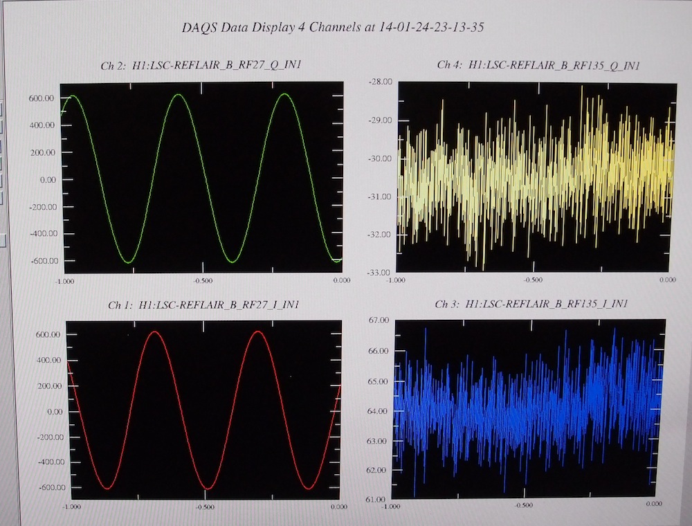
Quick check of the 3f chain has been done:
1) Applied a -40dBm (6.3mVpp) signal at ~27.5MHz to the input cable => obtained the output of 2.5Hz with the amplitude of ~1200Vpp (attachment 1)
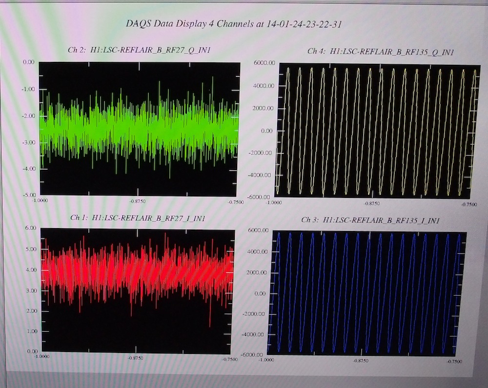
2) Applied a -50dBm (2.0mVpp) signal at ~136.5MHz to the input cable => obtained the output of 270Hz with the amplitude of ~11500Vpp (attachment 2)
There could have been the whitening filters turned on. So the response should be done again with more careful tuning of the input frequency.
- The RF diplexer amplifier D1300899
The demodulator was modified by Dick and tested by Yuta. The test proceduer is here. E1400033
The module is installed to the R3U8 for AS18 and AS90. There are LO signals labeled Ch1/2/3.
However, the diplexer channels for 9/18MHz are CH3 and CH4. So we need to confirm what the
correct channel assignment should be. This will affect the ADC channel assignment.
The V1 version in the dcc represents the as-built.