J. Oberling, R. Short, T. Shaffer
This morning we swapped the temporary SPI shutter cable, for the shutter in the SPI pickoff path on the PSL table, with the permanent one. Once the old cable was removed we fed it out of the PSL enclosure wall penetration to TJ, who then fed the permanent cable into the PSL enclosure for us (thank you, TJ!). The cable was secured in the same was as the temporary cable was, see attached pictures. We tried to physically move the cable into the ALS beam path and were unable to do so; at rest the cable is ~2.5" from the ALS path and the closest we could get it was ~2", so the cable is well secured and unable to drift into the ALS path. This cable had been successfully tested with a spare shutter before installation, but due to the ongoing CDS upgrade we were unable to test it with the installed shutter; this will be done once everything is back up and running. This completes LHO WP 13464.
TITLE: 07/28 Day Shift: 1430-2330 UTC (0730-1630 PST), all times posted in UTC
STATE of H1: Planned Engineering
OUTGOING OPERATOR: None
CURRENT ENVIRONMENT:
SEI_ENV state: CALM
Wind: 4mph Gusts, 2mph 3min avg
Primary useism: 0.03 μm/s
Secondary useism: 0.13 μm/s
QUICK SUMMARY:
Big item today/next few days is the RCG Upgrade, followed by access system work (taking down lasers), and this morning is cleanroom moving around Biergarten.
Last night, Betsy transitioned the LVEA to Laser Safe (Operations Phase...lasers can be on, VAC/Tables CLOSED). This Morning for the Access System work, we will be full on Laser Safe (Upgrade Phase...lasers OFF, VAC/Tables CLOSED)
IMC OFFLINE / JAC is DOWN. Just took SEI_ENV to MAINTENANCE. Will need to take SUS & SEI to desired states for the RCG work when we get the word.
WHOOPS!
Just noticed I forgot to hit "POST" for my Summary yesterday (We were transitioning to Laser Safety at "shift change"...and I was also trying to figure out how we shift change...since this is the first EVE shift I've had a hand-off for for a while! :)
TITLE: 07/27 Day Shift: 1430-2330 UTC (0730-1630 PST), all times posted in UTC
STATE of H1: Planned Engineering
INCOMING OPERATOR: Ryan C Oli
SHIFT SUMMARY:
Today was last full day before the big CDS RCG work starting tomorrow. With that, JAC crew worked on final checks. There were checks on subsystem SDFS. HAM7 SUS work continued. CDS did prep work for tomorrow. Toward the end of the shift Betsy worked on transitioning the LVEA to SAFE. And I'm handing off to Oli.
LOG:
Pending Filter Files:
h1calcs had a modified filter file waiting to the loaded. The running filter file was last loaded 16jul2026, H1CALCS.txt was modified at 10:52 27jul2026 and not loaded. I made a local copy of the modified file, then removed the changes by doing a subversion revert. This cleared the CFC flag on h1calcs.
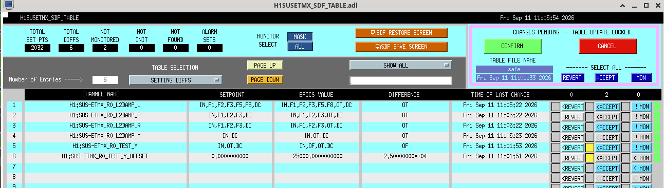
SDF Diffs:
Several models have outstanding SDF diffs (screen shots attached below)
| model | num diffs |
| susmc2 | 2 |
| susam | 8 |
| susomcab | 6 |
| susom1ab | 16 |
| susom2ab | 8 |
| susom3ab | 16 |
| isibs | 11 |
| isiham3 | 1 |
| isiham7 | 54 |
| calinj | 1 |
| calex | 1 |
Got some screen shots of a few different SDF Diffs.
I took these screenshots after Corey had already taken the SUS to SAFE state.
Also the LASER Stop button had already been pressed.
From what I can tell, I think we are mostly in a good spot for SDFs. The few items to note:
The two SDF screens we have are out of date. There have been many models added or names changed that we have not kept up with, and made this a bit harder. We will update these asap.
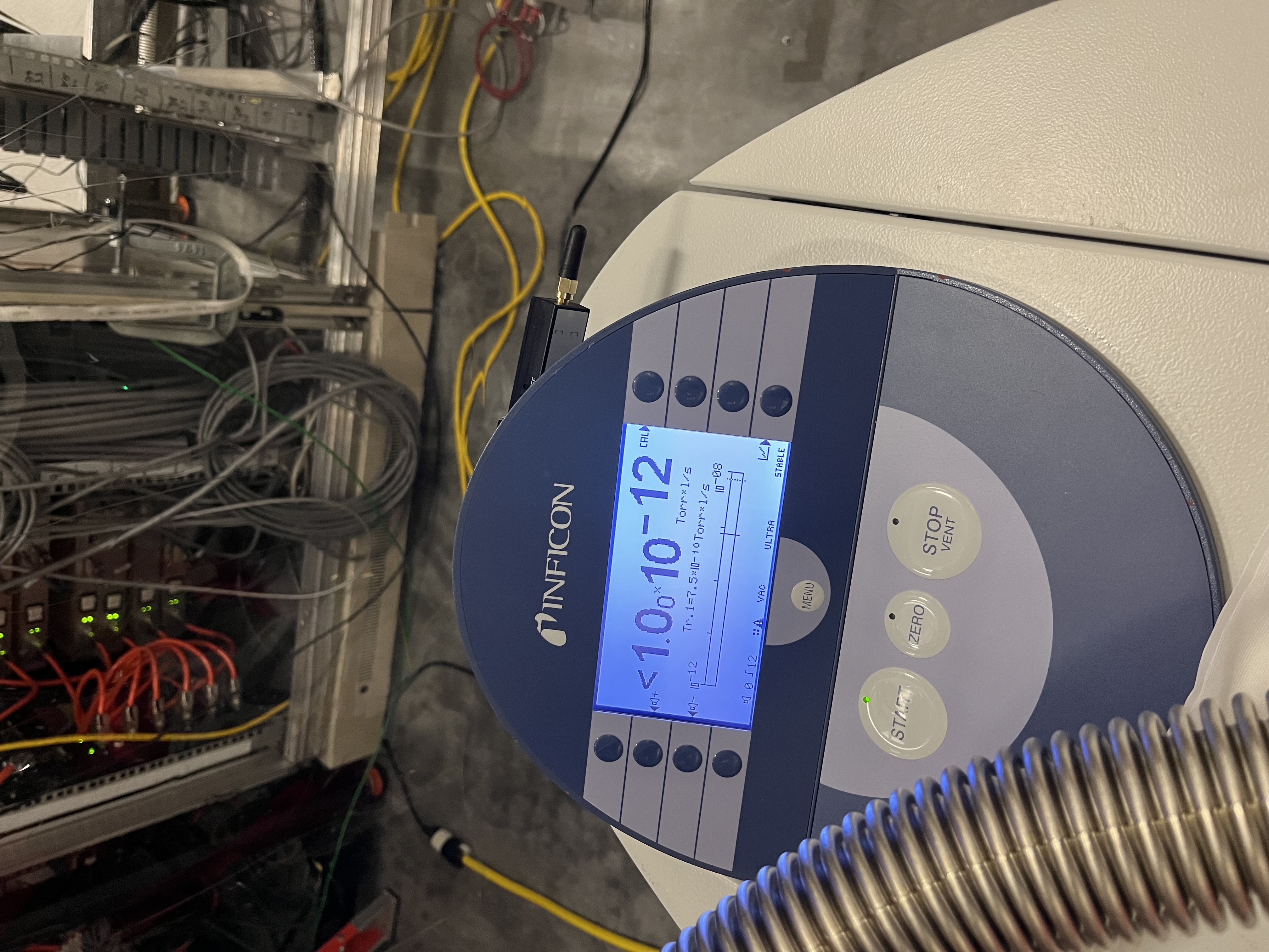
During the annual inspection of the LN2 tanks, we found that the LN2 tank for CP3 had a high vacuum jacket pressure (110 mtorr), see alog 90283.
We placed an ISP500 on the pump out port to get the jacket pressure back below 10 mtorr, this took ~30 hours of pumping to go from 110 mtorr to 9 mtorr.
No other LN2 tank needed pumpdown.
Closing WP 13448
Keita K, Khanh V, Jennie W
Summary: JAC angular control loops work now. We had some set backs this morning and eventually had to change some wiring at the IOT1 table but we have re-measured the phasing, re-measured the sensing matrix and now locked the 4 asc loops.
We tried to get our loops to converge this morning but we were seeing not much change in the loop outputs for large WFS gains (40000 eventually) and then eventually we could not see the two loops we tried (DOF1_P which feeds back to pitch and DOF2_P which feeds back to JM1) makign any improvement to the JAC transmitted power even if we changed the sign.
Keita and I checked the JAC phasing with the template at userapps/ioo/h1/templates/dtt/JAC_WFS_phase.xml and after checking the phase of the TF between the JAC length servo error point and the wavefront sensor error signals he realised that some of these were phased with the wrong sign. I did not think to check these in our previous round of phase measurements last week.
As a check of the signs in the ASC loop we slewed the beam to different quadrants on WFS A and B using JM1 and realised that the degrees of freedom on WFS A were swapped. I found a mistake in the WFS A DC input matrix where pitch and yaw were swapped. This is now fixed and I double checked these input matrixes were correct for both WFS sensors and the WFS B DC screen.
Using our previous phasing template JAC_WFS_phase.xml we used the picomotors in front of each wavefront sensor to check the wavefront sensor quadrant response to the 8Hz length signal. That is, we checked which wavefront sensor quadrant showed the highest magnitude response at 8Hz to the QPD quadrant the beam was in.
Quadrants 1 and 4 in each wavefront sensor show a maximum response to the beam being in quadrant 1 and 4 respectively. Quadrants 2 and 3 appear to be mis-matched between wavefront sensor and qpd. This holds for both WFS A and WFS B.
Keita and I went to the IOT1 table and unplugged WFS A segment 2, the channel H1:JAC-WFS_A_I2_INMON went to 0. The same was true for segment 3 and the channel H1:JAC-WFS_A_I3_INMON. This test was the same for WFS B also.
Since the table feedthrough was the easiest place to swap cables (it is hard to reach the back of the demod boards in the rack so we can't easily do it there) we went ahead and swapped them here.
Checks using the previous method with the 8Hz signal on the length and slewing the beam only into one quadrant of the WFS showed that this cable swap has fixed things.
I want to go back later to try and trace this DOF flip down, wondering if it might be in the jac simulink model or in the demod board connections.
After this swap we re-tuned the WFS phasing after recentering the WFS (with JAC locked). Then we re-measured the input matrix using the method from this (alog #91189), except we did not divide the matrix by the largest coefficient.
Keita and I checked over filters that Sheila had put in for PZT and JM1 feedback. We changed the poles at 0.8 and 0.85 HZ in pitch and yaw to be 0.83 Hz to match the zeros in the JM1 locking filters. We also tuned the gain of the exitsing filters to give a UGF of around 0.1 Hz.
After loading the new coefficients Khanh and I closed each degree of freedom in the ASC in turn. We kept tuning the gain up as the loops were converging very slowly. The final loop settings are shown here.
Here is the ndscope showing the loops converging and making the transmitted power higher.
(Jordan, Travis, Gerardo)
We removed and replaced the AIP for BSC6, no real complications while doing the work. However the joint at the AIP and the isolation valve has a tiny gap towards the bottom, we started pumping down on the system and it appears to be a solid union, we will go and visit tomorrow and see how the pressure is doing. On a side note we did find a flex metal hose that has a leak, it has been removed from circulation.
Went through and consolidated some sdfs for the output arm suspensions. These were for SR2, SRM, SR3, OFI, OMC, OMs, and FC1. Some suspensions had had their sdfs accepted while in SAFE, so I reverted those changes since they were all really just OFFSETs being off and OPTICALIGN sliders being off.
Jenne, Wanda V, Gizem K
Wanda and Gizem arrived today to help set up the DAS (distributed acoustic sensing) system that we're going to test for a few months. We're borrowing DAS interregators from EarthScope, and using spare dark fibers that go down the arms. The DAS will measure strain changes in the fibers. We've got 2 models of DAS interregator on site, however only commissioned one today. Both models are eye-safe, and have been registered with the LHO LSO.
Since we need to connect to the fibers that are buried along the inside of the arms, the interregators are set up in the MSR close to the fiber junction box.
Fil did the actual connection to the LIGO fiber box, connecting some short 10m fibers that Wanda brought. We're using fiber #24 on Xarm (the fiber junction box calls this Right) and fiber #24 on the Yarm (the junction box calls this Left). Gizem took OTDR (optical time delay reflectrometry) measurements of each of our 4km fibers (one on the Xarm, one on the Yarm). The reports are attached here. One of the connectors (likely at the junction box) on one of the arms is a little lossy (0.6 dB loss), but since it's the junction box we're just going to live with it. Also, one of the splices at the midstation is better than the other (I think it's the Yarm that is better). More details are in the attached pdfs from the OTDR measurements.
We elected to just use rack 120V, rather than the UPS 120V, since we don't have long enough UPS-specific power cables. The power here on site is plenty good quality for the DAS.
We watched the data live on the monitor that is set up with the interregator in the MSR, and indeed it's working! We're going to leave it running overnight and have a look tomorrow at the data, particularly to see the quiet time in the middle of the night.
The attached photo is of the setup we've got on the far side of the MSR. The black case is the Febus DAS interregator, and we've got a 21 TB hard drive attached to collect the data. The fibers go up in the overhead tray, then down to the junction boxes which are at the very top of that first rack.
Tomorrow we will start work on the following to-do items:
Elenna, Oli
We spent some time figuring out SDFs for the BBSS. It should be all good to go.
A couple of notable channels that will need to be figured out at some point are:
I've attached a pdf with the full list of sdf diffs that we accepted. The notable channels listed above are highlighted as * and **
Just want to add a note that for MICH locking we have been doing so successfully without oplev damping. We'll have to monitor once we get to PRMI and DRMI locking, but for now leaving the OLDAMP gains at zero is ok.
The Y2L gain seems like a spot position change, but I'm not aware of any spot position control on the beamsplitter specifically.
Ryan C, Rahul
In preparation for our second replacement of the PSAMS, we have taken SUS ZM5 out of HAM7 chamber and staged it on the table next to it. We took the bottom stage PSAMS out of the suspension cage - this unit has wires shorting inside the mirror housing.
Tomorrow morning we will start replacing it with the unit CIT has shipped us - which was originally installed in ZM5 (LHO) but broke down two weeks ago (Strain Gauge wire leads got loose inside), then got fixed at CIT and re-shipped to us with 65 in-lb torque.
Camilla, Rahul
SUS ZM2 in HAM7 chamber needed a pitch offload since it was using up a lot of DAC output. This morning we went to HAM7 chamber and at first confirmed the beam alignment and its position on the irises. Then I entered in HAM7 chamber and locked the suspension and unlocked the pitch adjuster screw. At first I gave it a full 1 turn anti-clockwise making ZM2 pitch down (and then unlocked the suspension) and Camilla confirmed that the alignment looked better but perhaps we overshot by a small amount. I retracted by 1/4 turn (thus making 3/4 turn anti-clockwise in total) and then the beam looked good on the iris. Before exiting the chamber I locked the screw for pitch adjuster and checked if all EQ stops were set free from the suspension chain.
Finally Camilla adjusted the alignment sliders on ZM2 for fine tuning it.
I took a quick chamber side transfer function measurements and the suspension was found to be healthy.
Here is Rahul inside HAM7, next to ZM5.
While I was fine tuning the alignment after this offload, I realized that the PSAMs setting was wrong. It appears that while this ZM2 work was happening that the ZM2 strain gauge reading has been shifted. We still have the same ΔV of 5V but the range used to be 1.2 to 6.2V plot and now is 4.6 to 9.6V plot. CIT has possibly seen this before in T2300426 but the effect was less.
Our nominal was 3.15V before, now I'm assume it should now be 6.55V (4.6V + (3.15V - 1.2V)). We will confirm this with beam scan measurements in chamber.
Ryan and I went to ZM2 PSAMS strain gauge at 6.55V and took data in 2 similar locations to in 91142. The beam size lis very similar to expected so we think ZM2 is fine, just the strain gauge now has an offset. Will look at the data in more detail tomorrow.
The data we took is attached. This plot shows the old data with SG at 3.15V in light/dark green and yesterday data at 6.55V in red/orange, It is very close. Also attached is the data taken 0.5V above and below the nominal SG values, both before when nominal was 3.15V (in blue/green colors) and now when it is 6.55V (in orange/purple/red colors). We conclude that the new nominal is << 0.5V from the old nominal. We are fine to stick with 6.55V as ZM2 PSAMS and can treat this as the old 3.15V.
Alignment sliders for the "new ZM2 position" are now P +300, Y -155.. Maybe we could do a little more fine tuning of the retrorefection and need to measure the power through the OPOS.
Ryan S, Camilla