Today I did a quick tune-up of the PSL FSS alignment, as the TPD had been trending down and remote alignment wasn't bringing it back to its usual level (an indication an on-table alignment tweak is needed). I began by taking a quick power budget of the FSS beam path:
The single-pass diffraction efficiency is roughly where it normally is, but the double-pass diffraction efficiency is lower than usual. To correct this I slightly tweaked mirror M21 to tweak the double-pass alignment. After the tweak:
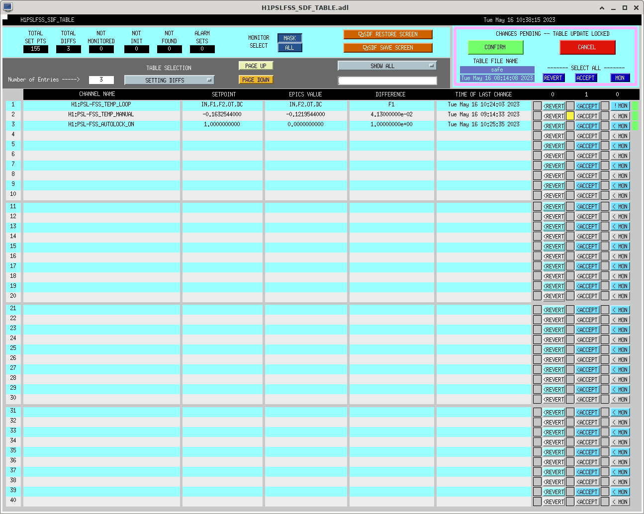
While not as high as we've seen in the past, this is close enough to where we generally run so I began recovering the RefCav. The alignment was far enough off that I had to lock the RefCav manually (this generated an SDF diff for H1:PSL-FSS_TEMP_MANUAL, which I accepted), then used the picomotors to tweak the alignment. In then end, I ended up with a RefCav TPD of 0.961 V. Finally, I adjusted the alignment into the RefCav RFPD and took locked and unlocked measurements for a quick visibility calculation:
I then left the enclosure and turned on the ISS. With the enclosure environmentals off and the ISS on, we now have a RefCav TPD of ~0.980 V. I've attached a screenshot of the accepted SDF diff from the manual RefCav locking; only the highlighted SDF difference was accepted, the other two differences are due to the RefCav being unlocked with the ongoing CER power supply work, which took down the RF distribution system and unlocked the PMC and RefCav. They will go away once the RefCav is locked at the end of maintenance. This closes WP 11201.
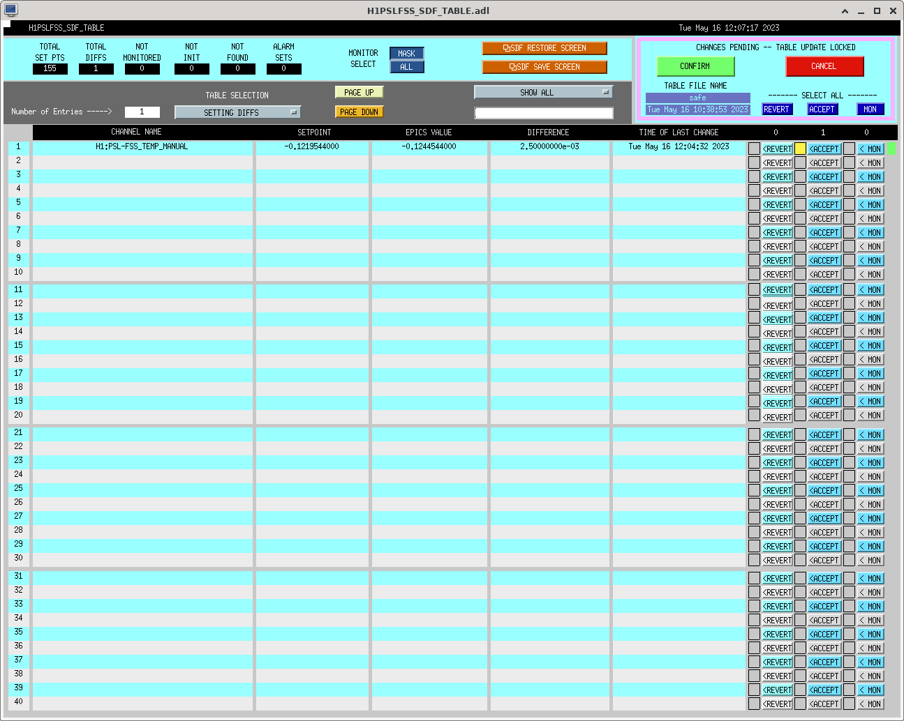
When re-locking the RefCav after RF was powered back on, I had to do it manually at first. It would catch, but then oscillate and would not stop and the autolocker would not engage the temperature loop. Once I re-locked manually and manually engaged the temperature loop, the oscillations stopped. The manual re-locking necessitated a change in H1:PSL-FSS_TEMP_MANUAL again, with corresponding SDF diff, so I acccepted it and attach a screenshot here. Will keep an eye on the RefCav to see if this behavior with the autolocker continues.
Tue May 16 10:10:00 2023 INFO: Fill completed in 9min 59secs
Richard confirmed a good fill curbside.
Due to some concerns raised by Evan Hall regarding vibration and noise from the # 1 supply fan at End X, I have switched from Fan 1 to Fan 2.
Tagging ISC, PEM, and DetChar -- this is a follow-up action taken now that we've found that the detector is particularly sensitivity to scattered light from the ETMX cryo baffle; see LHO aLOGs 69598 from Evan, and 69603, Andy's ID that it may be this fan that Bubba has now turned off as indicated in the above aLOG. The game plan: since improving the isolation / damping of the cryo baffle would require an end-station vent which we're not willing to do, we're instead looking to reduce the input motion to the cryo baffle's isolation system.
Last night after this change, the detector was left in observing mode for roughly 9 hours. This data that does not contain any visible 4 Hz glitching (see attached spectrogram). Additional checks of data during daytime hours would be helpful to confirm that the 4 Hz glitching is no longer an issue, but this is a promising sign.
D. Barker, C. Gray, J. Kissel, B. Weaver, T. Shaffer In order to prepare for the work Marc & co. are doing today re-organizing the DC power supplies to the ISC and SQZ racks work permit (WP 11193), we thought hard about the racks and subsystems impacted by that work. As such, we've taken the following actions (in the order listed): - IMC -- was locked, un-managed the IMC_LOCK guardian, and brought the state request to OFFLINE. - Filter Cavity -- was locked on green, brought the SQZ manager to DOWN - The following computer systems for ISC models are using ADCs and DACs from the similarly named IO chassis are powered by the power supplies in the WP -- including even some (again, but not all) CHANS_NOT_MON, :: h1iopomc0 >> This IO chassis is in rack SQZ-C1, whose +24V power is going to be changed to be supplied by a different power supply (needed due to actions 3 and 7 listed in WP) - h1omc - h1omcpi :: h1lsc0 >> This IO chassis is in rack ISC-C1, whose faulty -18V power supply is going to be replaced (needed due to action 8 listed in WP) - h1lsc - h1lscaux - h1sqz - h1ascsqzfc :: h1asc0 >> this IO chassis is in rack ISC-C1, whose faulty -18V power supply is going to be replaced (needed due to action 8 listed in WP) - h1asc - h1imcasc - h1ascsqzifo So, - we browsed through (though did not peruse) the SDF systems for the above listed models, confirmed that there were no SDF diffs for these model's monitored signals (and even some). Didn't find any, but accepted the unmonitored, guardian controlled, signals for the h1omc just so we start from a better place (e.g. the DARM offset was set at -42 rather than the modern 9.7). - Finally, we asked Dave to power down these IO chassis safely by first removing them from the Dolphin Network, and then shutting down all the front-end processes, and he has now done so (see LHO:69630). We're ready for ISC rack power supply work!!
WP 11193 The primary motivation for today's work is to truly isolate the DC power supply for new, segregated h1omc0 IO chassis that houses only the new 524 kHz low-noise ADC which reads out the OMC DCPDs -- i.e *the* DARM gravitational wave sensors -- from known loud RF source generators, like Bekchoff chassis and the RF distribution system. That rack, SQZ-C1, had been powered by a cobbled together mish-mash of available DC power supplies in the DC power rack H1-VDC-C2, which powers lots of other things including RF sources, which -- we suppose -- are polluting and down-converting the OMC DCPD (the DARM) sensitivity. So, technically, you might say this work falls under the scope of ECR E2200441, and IIET Ticket 25756. This covers actions 1, 2, 3, and 4 below. The secondary motivation is to continue the campaign of replacing ailing and failing power supplies. I'll leave it to Marc to aLOG what actually happens today (cite the old addage "plans are out of date as soon as you make them"), but for historical reference, here's the list of changes he's planning on doing plus some context as I understand it, and a gathering place for all of the drawings and serial numbers involved. Actions: * This swap is to keep the SQZ and ISC supplies grouped together. 1 - Add a +/-24V tap to the C4 junction box above H1-ISC-C4, connect tap to internal +/-24V source. # Impact: TEMPORARY BAD: ISC-C4 must get powered down, GOOD: segregating the h1omc0 # IO chassis power (in SQZ-C1) from RF distribution system, less lines in DARM 2 - Move +/-24V sequencer cable from C3 junction box to new C4 junction box +/-24V. # Impact: TEMPORARY BAD: ISC-C3 must get powered down, GOOD: segregating the h1omc0 # IO chassis power (in SQZ-C1) from RF distribution system, less lines in DARM 3 - Move H1-SQZ-C1 cable in H1-VDC-C2 Power Rack from U26 to U34 RHS, set U34 RHS Kepco to +24V. # Impact: TEMPORARY BAD: SQZ-C1 must get powered down, h1omc0 IO chassis must get # powered OFF, GOOD: h1omc0 IO chassis gets this dedicated power supply, less lines in DARM 7 - Install new power run from H1-VDC-C2 to H1-SQZ-C1 for +24V supply for the segregated SQZ-IO [h1omc0] chassis. # Impact: TEMPORARY BAD: SQZ-C1 must get powered down, h1omc0 IO chassis must get # powered OFF, GOOD: h1omc0 IO chassis gets this dedicated power supply, less lines in DARM * balance load between the two Beckhoff +24V power rails 4 - Move H1-ISC-C3 cable in H1-VDC-C2 Power Rack from U34 to U26 RHS, set U26 RHS Kepco to +24V. # Impact: TEMPORARY BAD: ISC-C3 must get powered down, GOOD: as stated in Marc's work permit, # balancing the DC power to Beckhoff chassis, and a cable rearrangment fall out of Action 3 above 5 - Move +24V H1-ISC-C3 Breakout Rail input cable to old H1-ISC-C3 +24V junction box above rack. 6 - Move ISC-Beckoff +24V cable from IO-ALS & IO-LSC power and to the new +24V power rail powered from H1-ISC-C3. * repair failing power supply 8 - Replace H1-ISC-C1&C2 -18V RHS with new supply. # Impact: TEMPORARY BAD: ISC-C1 and ISC-C2 must get powered down, GOOD: noise source from failing power supply mitigated Systems Affected: ISC-RF Generation ISC-C3 & ISC-C4 ISC-Signals Conditioning ISC-C1 & ISC-C2 ISC-Beckhoff in ISC-C3 SQZ-IO Chassis in SQZ-C1 SQZ-C1 - Primary Functions: New home for Segregated OMC IO Chassis (and AA Chassis) and SQZ system's Beckhoff chassis - Wiring diagram: D1100683 for Bekchoff, New Segregated OMC IO Chassis Location Not indicated in D1900511 - Graphical layout: D1600513 for Beckhoff, New Segregated OMC IO Chassis Location Not indicated in D1600513 - Serial Number: S1800536 H1-VDC-C2 - Primary Function: +/-18 and +/-24 V DC power supplies for many PSL, ISC and SQZ racks (and +/- 18 V for SUS field racks, SUS-R1, SUS-R2, SUS-R3, SUS-R4) - Designation of which power supply powers which rack D2300167, page 7 - Serial Number: S1301896 H1-ISC-C1 - Primary functions: Audio Frequency ("Fast") Signal Conditioning for LSC and ASC IO chassis, and the IO chassis themselves - Wiring Diagram: D1900511, pages 1 and 2 - Graphical layout: D1001427 - Serial Number: S1301876 H1-ISC-C2 (Not involved in today's work) H1-ISC-C3 - Primary functions: (Radio Frequency) RF distribution and CER IO Chassis Timing Fanout - Wiring diagram: D1900511, pages 6 and 7 - Serial Number S1301878 - Graphical layout: D1001427 - Note: timing system is powered by different power supplies that the work planned today, so the work today should not impact CER timing system. #crossfingers H1-ISC-C4 - Primary functions: RF generation and distribution system RF oscillators and DEMODs used by PSL, IMC, ALS, SQZ, LSC, ASC, etc. - Wiring diagram: D1900511, pages 8 and 9 - Graphical layout: D1001427 - Serial Number: S1301879
Additional Effects From This Morning's Power Supply Work For The ISC RF Racks:
See LHO:69652 for Marc's description of what was actually completed. In short, they did NOT do Actions 7 -- isolate the h1omc0 IO chassis on its own power supplies, nor did they do action 8 -- replaced the failing power supplies that support ISC-C1 and ISC-C2.
WP11193
In prep for Marc's IO Chassis power work, on h1omc0, h1lsc0, h1asc0 all models were stopped and these FE were fenced from the Dolphin fabric.
See further info in LHO:69631.
Mon May 15 10:12:00 2023 INFO: Fill completed in 11min 59secs
Travis confirmed a good fill via camera.
TITLE: 05/16 Day Shift: 15:00-23:00 UTC (08:00-16:00 PST), all times posted in UTC
STATE of H1: Observing at 123Mpc
CURRENT ENVIRONMENT:
SEI_ENV state: CALM
Wind: 12mph Gusts, 9mph 5min avg
Primary useism: 0.03 μm/s
Secondary useism: 0.12 μm/s
QUICK SUMMARY:
H1's currently OBSERVING, but just popped out for the Magnetic Injection (1445utc) and the lock clock is at 9h55m. PI24 just had an alarm. On the CDS Overview I see some red from Excitations, ADC, Overflows (some are from Magnetic Injections & possibly in-lock SUS charge measurements. H1DARM stopped on nuc30, and then crashed when I tried restarting....reopened via the visible terminal which was behind dtt window that had the command line ready to go.
While LLO were not Observing, I took some SQZ data to help better understand our SQZ angle for future overnight tests. Our squeezing hasn't been great over the last few days, we expect as our NLG and power though the SHG have decreased, we will go onto SQZT0 tomorrow.
Naoki, Sheila, Vicky. It was great that Camilla did these meausurements last night!
OPO TRANS DC POWER = 39.6 uW. According to calibration on 2/3/23, which has been pretty trustworthy, this is about NLG = 3.92, so generated SQZ = 9.24dB.
Based on the no-sqz data at this time, IFO losses are below 35%, and more like 20-30%. These sqz/asqz levels suggest either significant 50% squeezer losses (15-30% excess sqz losses from ifo losses), or that our NLG is mis-calibrated/mis-tuned due to wrong opo temperature at the time.
If we had only the known levels of squeezer injection losses (say common 20-30% losses with ifo + additional 7% sqz injection losses, total ~30% loss), I'd expect we'd have seen ~7.5-8 dB asqz, and over -3.7dB sqzed noise reduction, which was clearly not the case.
Assuming fixed/real NLG, adjusting losses to match observed sqz/asqz. With NLG = 3.92, this gives generated SQZ = 9.24dB. To only see Anti-SQZ = 6.5dB and sqz = -2.5dB, suggests the squeezer sees 45-50% total losses, so like 15-30% excess of ifo losses.
Given these SQZ/ASQZ levels, calculate NLG and losses. Best-case for losses, an NLG=3.3 and losses 42% would be sensible. This is still excess 10-20% sqz losses from ifo losses.
What was our NLG? Today Naoki measured NLG=3.75 after several DAQ restarts. This would need about 50% sqz total losses, 15-30% excess sqz loss from ifo losses.
Potentially the opo co-resonance temperature is mistuned for red/green co-resonance, given that I'm not sure we re-tuned the OPO temp optimally with this lower NLG and the recent LVEA temperature drifts. Maybe our AS42 offsets are also bad, we have not updated them in a while, and there have been many computer restarts last week. As well, we've had FC alignment/ASC changes; we've checked for clipping but maybe with recent computer restarts it is worth double-checking. We'll check everythign again after today's sqzt0 table work, and see if we can reconcile these numbers. We can try to more often quickly check asqz/mean-sqz to better understand our losses.
I checked the logic and removed the weighted the edge between SQZ_ASC and FREQ_INDEP_SQZ in SQZ_MANAGER so it should now go straight to FIS if it is requested. It can also go between FIS and FDS as icky and I previously added.
Looking into why SQZ_FC was slow (3 minutes) getting from FIS to FDS, see attached:
As the FC goes from FIS --> FDS, the FC guardian is bringing FC2 from MISALIGNED --> IR_LOCKED. But in the process of physically moving FC2 back, it is free-swinging, and I wonder if maybe the CLF glitches through FC resonance in this time. The CLF going through FC resonance kicks the LO loop, which kicks TTFSS, and in turns brings down the LO loop, causing SQZ_MANAGER to go back to SQZ_READY_IFO, since it looks like the LO loop failed. When we're locked next, we can check if the LO loop can stay locked while the CLF glitches through, and if it can, maybe the guardian brings down the LO loop pre-emptively even if it doesn't have to.
Maybe we don't care to switch faster between FIS --> FDS. But if we do, I wonder if we could just tune the FC out of band, as far as the RLF-CLF can go. Or, we can bring FC-IR back with bdiv closed, or open with the LO loop unlocked. If we need to do this for upcoming sqz scans, I think we can smoothen out this transition.
To comment about the losses quoted above -- I think the losses were weirdly high b/s squeezer was in a not optimal way, related to our SDF mess after computer restarts, maybe our low NLG and higher CLF powers we happened to be using for a week or so, and other semi-random technical problems that have popped up over the last 1-2 weeks. I think our previous measurements of 3.5-4dB SQZ exclude losses of order 50%, when the squeezer is operating nominally and things are "normal". But we will check asqz/sqz more regularly now, to help track losses.
TITLE: 05/16 Eve Shift: 23:00-07:00 UTC (16:00-00:00 PST), all times posted in UTC
STATE of H1: Observing
SHIFT SUMMARY:
LOG: Leaving the IFO in observing, has been locked 2h30. Elenna plans to take the IFO briefly out of Observing ~1am to take LSC FF injections.
03:07 UTC Lockloss 1368241693
Adrian was running an injection on H1:PEM-CS_GDS_6_EXC, it came up on the CDS model GDS table but not on the OPS > TEST POINTS screen, see attached. Tagging CDS.
| Start Time | System | Name | Location | Lazer_Haz | Task | Time End |
|---|---|---|---|---|---|---|
| 22:53 | VAC | Jordan & Gerardo | Mid X | N | Dropping off parts | 23:15 |
| 23:03 | PEM | Robert, Anamaria | EY | N | EY Shaker move | 23:50 |
| 23:03 | COMM | Elenna | CR | N | Mich OLG | 23:24 |
| 23:24 | PCAL | Tony | PCAL Lab | local | PCAL (stepping past LVEA change room for laptop) | 23:46 |
| 23:57 | PEM | Robert, Adrian | LVEA | N | East Bay PEM speaker set up | 00:13 |
| 02:14 | PEM | PEM Team | CR | N | EY shaker injections with ETMY A2L moves | 03:07 |
| 03:07 | IFO | Lockloss from EQ | ||||
| 03:21 | PEM | Adrian | CR | N | PEM Magnetic Injections while locking/first minutes of NLN | 05:21 |
| 06:19 | SQZ | Camilla | CR | N | SQZ angle adjustments | 7:15 |
Once we got to observing and ADS was converged, we couldn't go to Observing as the IFO guardian was reporting ISC_LOCK "NOT OK". ISC_LOCK looked okay, it was arrived in NLN and reporting DONE, see attached medm screens and guardian states.
IFO went to Observing on it's own at 05:13UTC. The logs (attached) show that nothing happened in ISC_LOCK at the time IFO got requested to go from WAITING_FOR_NODES to OBSERVE.
The IFO node and ISC_LOCK node were functioning correctly, but we'll need to make a change.
ISC_LOCK was not OK=True (1) because one of its subbordinates was not OK, VIOLIN_DAMPING. The violin guardian finished its 'monitor pause' timer and then transitioned to DAMP_VIOLINS_FULL_POWER at 5:12:58UTC where it then went into its OK=True (1). ISC_LOCK and The IFO node quickly followed and 6 seconds later we were in Observing.
I time machined the Guardian Overview screen to 05:12:57UTC and you could see the violin guardian not OK. This node didn't show up in the IFO list of not ok nodes because it's currently in our exclude list. This clearly creates an issue since it is managed by ISC_LOCK and all of ISC_LOCK's subbordinates need to be OK in order for ISC_LOCK to be OK. I confirmed with Rahul that we don't need to go to the DAMPING_ON_SIMPLE state to adjust modes in full power anymore, so I've taken the VIOLIN_DAMPING node out of the exclude list.
Elenna, Camilla. We were wondering why our X-arm green locking signal isn't 1 anymore: Green H1:ALS-C_TRX_A_LF_OUT_DQ level reduced from 1.0 to 0.9 on 29th-30th August 2022.
During this 30 August 2022 Tuesday maintenance we had troubles locking ALSX (alog 64742) and during maintenance Daniel reduced the ALSX laser current/ measured power (alog 64752), see attached. This explains the change, maybe we already knew this at the time.
IFO has been locked for 4h30. Currently in commissioning with the PEM team actively shaking EY. Range is 80Mpc, low due to these injections.
At the start of April, Jennie Wright adjusted the DARM BLRMs filters to make them accurate for O4 (similar to SQZ in 66753). Since then we could make some more updates, see attached template for BLRMs today. This was while PEM was injecting at low frequency, but BLRM#5 needs a couple of lines removing.
Jennie's template is located in /opt/rtcds/userapps/release/lsc/h1/templates/DARM_BLRMS.xml and the BLRMS medm is accessed via sitemap > LSC > RANGE BLRMS
Adrian, Erik, Fil, Johnathan
The PEM CS radio receivers have been marked as faling on LIGOcam for awhile. We entered the MSR and unplugged and re-plugged the RF spectrum analyzer box mounted to one of the racks there. The remote UO PEM team (Ben, Matthew) report that this has cleared up some of the errors they were seeing trying to get the sensor reporting as working online. We restarted the box on May 15 at 16:20 local time.
I took an OLG of MICH afte we entered NLN. In the past we have set this UGF to be around 7 Hz. My measurement showed a UGF closed to 5 Hz. We have very little phase margin on that side, so I increased the gain by 3 dB to get us back to 7 Hz UGF. Measurement is saved in "/opt/rtcds/userapps/release/lsc/h1/templates/MICH/MICH/MICH_OLG_NOISE_FULL_LOCK_NLN.xml".
The gain increase was placed in lownoise_length_control. Old gain was 2.3, new gain is 3.2.
The nominal settings for ITMY mode05/06 has stopped working past few IFO locks and both the modes are gradually growing. The nominal setting had a -30 deg phase filter engaged with a gain of -0.01. I tried flipping the sign but the mode was still growing. Hence I switched off FM2 (-30 deg phase filter) and applied a positive gain, which looks to be working (during the last lock) - see screenshot of the ndscope which shows both the modes damping down slowly (both narrow and broad band monitor filters). Given below are the setting which I will try in the next lock and if everything goes fine then I will make the changes in lscparams and accept them in the SDF.Observe file.
IY05/06 FM1 + FM10, Gain +0.01
Also, for IY07 someone found the mode to be growing with -60deg phase filter engaged (I see a comment on lscparams). I tested it this morning and found it to working fine with the -60degree phase filter. I will keep an eye on this mode but at the moment I am going with the following filters and gain,
IY07: FM1+FM2+FM10 Gain +0.1
Accepted the changes for IY07 on SDF.OBSERVE, screenshot is attached below.
I can confirm that the new IY05/06 settings work well for multiple locks. They can be guardianized!
I have confirmed the above settings in the lscparam.
Attaching a plot from last night (6 hours of damping went fine).
I have calibrated the CHARD and DHARD in-loop error signals using the L2 witness and L3 oplevs.
I use a similar method to obtain the calibration that I have used in calculating the REFL sensing matrix. I turn on notches in all ASC loops at 8.125 Hz, so I don't have to consider loop effects. I inject into CHARD/DHARD at the "SM" injection point at 8.125 Hz (3000 exc counts). I obtain the transfer function from a test mass, such as ETMY L2 wit to the sensor, such as REFL A RF9 I (10 averages, coherence ~0.99). This gives me a result in WFS cts/ microradian of L2 motion. I have previously measured (and modeled) the L2 wit microradian to L3 oplev microradian transfer function, and I use that to convert from L2 urad to L3 urad (73 uradL2/uradL3 pitch, 45 uradL2/uradL3 yaw). These signals are also normalized by PSL input power (76W for these measurements). The DHARD signal is purely AS A RF45 Q, whereas the CHARD signals are a weighted sum of all four REFL I signals (see CHARD input matrix for values).
DHARD P = 4.2e-11 rad/ct
CHARD P cal = 8.8e-11 rad/ct
DHARD Y cal = 5.2e-11 rad/ct
CHARD Y cal = 4e-11 rad/ct
The resulting in-loop RMS for each HARD loop are as follows: DHARD P 0.32 nrad, CHARD P 1.6 nrad, DHARD Y 0.36 nrad, CHARD Y 1.3 nrad.
These results are similar to values Marie Kasprzack estimated for Livingston ASC in 2021 (see slides 6 and 7 of G2100751). However, they are very different from values that Rana estimated recently at LLO using a much different method, see LLO:64562.
Rana’s method calibrated the WFS with respect to the cavity axis angle, while this method is with respect to the angle of a test mass. Since the g factor of the arm cavity is close to 1, the former is much larger than the latter.