Naoki, Camilla, Vicky
For O4, we have swapped the CLF path's M5 mirror optic back its original 5:95 beam-splitter. This is the design (D1201210), and how it will be for O4. CLF ISS settings have been accordingly to our recent CLF ISS OLG measurements, with AOM RF @ 25.7dBm, and so ISS gain at 23dB (May 2023, LHO:69268). CLF_LAUNCH PD beam-splitter ratio has been updated and SDF'd according to our table measurements with the Thorlabs power meter (screenshot).
Some history of swapping the CLF BS/mirror:
-- July 2022. When we had the broken CLF fiber on HAM7 in Summer 2022, we replaced the CLF BS 5:95 to a mirror to get enough CLF power to lock, LHO:63893, ~July 2022.
-- Dec 2022. After fixing the fiber feedthrough, we swapped it back to the 5:95, LHO:66260.
-- Late-Jan 2023. LHO:67038, we swapped the CLF path back to a mirror to investigate how high-CLF levels can inject technical noise and limit squeezing.
-- Late-April 2023 68991+ 69084, Nutsinee and Daniel made interesting measurements of CLF intensity noise in DARM, related to RF AM at the CLF frequency, which is projected something like a factor of 8 below DARM. They installed an RF intensity noise monitor, LHO:69013, that'll live on SQZT0, so we can continue to monitor RF AM -- note: this intensity noise monitor is currently demodulated using the homodyne demod board e.g. SQZ-HD_DIFF_RF3_DEMOD_RFMON, so we will not be able to use the homodyne for now.
-- Some summary alogs looking at CLF noise due to seeding or AOM RF drive power: LHO:67038, 67068, 67210. It seemed to us then that, driving the AOM at high RF powers was better.
-- LHO:67219 Feb 2023, our most recent NLG sweeps on the homodyne measured up to 5.5 dB SQZ on HD, and suggested there was some technical noise about 10dB below shot noise, alongside ~25% loss and ~15 mrad phase noise.
Today during lock I adjusted the demodulation phase of the SRC1 ASC loop to see if I could see improvement in DARM optical gain. Given that we are needing such a large SRCL1 offset to retune SRCL and adjust the DARM spring, it is worth considering if the SRC has alignment offsets that are affecting these parameters. AS A RF72 is the interferometric sensor for the SRC.
I stepped the four demod phases for the quadratures of the WFS and monitored kappa c and cavity pole. Looking at past locks it appears that both kappa c and the cavity pole change by about 2% during thermalization. I decided that a good metric of success would be witnessing changes in kappa c great or less than the usual 2% change of thermalization. I first increased the demod phases by about 30 degrees. Kappa c increased during this time by 2% only. To confirm, I undid the change in phase and saw no corresponding change in kappa c. I then decreased the demod phase from nominal by 30 degrees. I also saw no change in kappa c. I have reverted these changes.
I have attached a scope showing the various traces I mention during this test.
I think it's worth trying this test one more time after the IFO has thermalized and the kappa c has settled.
GPS start of test: 1367712405
GPS stop of test: 1367717069
TITLE: 05/09 Eve Shift: 23:00-07:00 UTC (16:00-00:00 PST), all times posted in UTC
STATE of H1: Lock Acquisition
CURRENT ENVIRONMENT:
SEI_ENV state: CALM
Wind: 23mph Gusts, 17mph 5min avg
Primary useism: 0.04 μm/s
Secondary useism: 0.14 μm/s
QUICK SUMMARY:
IFO status : Relocking in Find IR.
The attached figure shows the 26 days trend of the offset of camera servo. Apart from PIT2, the offset changes by a few count which seems reasonable. However, the offset of PIT2 changes by ~120 count in different lock. There seem to be two offset trends which are -155 and -274. The PIT2 controls the X arm SOFT using ETMX camera. I am not sure what this offset change means.
EDIT: Jenne pointed out that it could be because the SDF in safe.snap reverts the offset to bad value. I checked the SDF and found that the offset is set to -274 in safe.snap. I changed the offset to -155 and accepted it in SDF.
TITLE: 05/09 Day Shift: 15:00-23:00 UTC (08:00-16:00 PST), all times posted in UTC
STATE of H1: Lock Acquisition
SHIFT SUMMARY: Made it back to NLN after maintenance for 35min. No initial alignment was done, but we did have to run Check MICH. We lost lock very suddenly for reasons unknown so far. Relocking now.
LOG:
| Start Time | System | Name | Location | Lazer_Haz | Task | Time End |
|---|---|---|---|---|---|---|
| 15:05 | Fac | Chris, contractors | LVEA | n | Vinyl flooring | 19:07 |
| 15:06 | VAC | Jordan | EY | n | Running turbo pump | 18:16 |
| 15:07 | Fac | Mitch, Randy, contractor | EY | - | Wind fence | 19:09 |
| 15:21 | PSL | Jason, Ryan S | PSL enc | Local | Alignments, measurements | 19:15 |
| 15:22 | PEM | Fil, Adrian | LVEA | n | Mircophone checks (1,2...) | 18:33 |
| 15:23 | Fac | Kim, Cindi | EX | n | Tech clean | 16:54 |
| 15:26 | TCS | Camilla | EY, EX | n | Turn off HWS lasers and cameras | 16:06 |
| 15:26 | VAC | Travis | EY | n | Hepta pump work | 17:50 |
| 15:30 | Fac | Christina | CS | - | Moving pallets | 17:08 |
| 15:39 | SUS | Ryan C | EX | n | OpLev charge measurement | 16:57 |
| 15:56 | CDS | Marc, Fernando | CER | n | Power supply fan swaps | 18:02 |
| 15:56 | VAC | Mike Z, Janos | LVEA | n | Parts hunt | 16:50 |
| 16:23 | CDS | Jonathan, Jamie | - | n | GDS/DMT work | 17:23 |
| 16:37 | CDS | Dave, Daniel | - | n | H1IOPLSC0, SQZ, OMC model restarts | 17:37 |
| 16:39 | Fac | Chris | EY, MY, CS, MX, EX | n | Famis checks | 19:14 |
| 16:42 | SEI | Jim | Office | n | HAM2/3 HEPI FF measurement | 18:04 |
| 16:54 | Fac | Kim, Cindi | LVEA | n | Tech clean | 18:46 |
| 17:23 | ENG | Betsy | LVEA | n | Take measurements on LVEA floor | 17:59 |
| 17:51 | VAC | Travis | LVEA | n | Looking for parts | 18:01 |
| 17:53 | VAC | Norco | MX | - | LN2 fill (CP5&6) | 19:27 |
| 18:15 | Slow | Daniel | CR | n | Beckhoff restart | 18:25 |
| 18:29 | CDS | Marc | EY | n | Power cycle Beckhoff chassis | 18:49 |
| 18:32 | SQZ | Daniel | LVEA | n | Put back equipment | 18:38 |
| 18:33 | PEM | Fil, Adrian | EY, EX | n | Plug in coils | 19:27 |
| 18:59 | CDS | Fernando, Marc | EX | n | Parts find | 19:20 |
| 20:17 | VAC | Travis, Jordan, Janos | MX | n | Hepta work | 21:19 |
| 22:00 | SEI | Jim | Office | n | HAM3 FF testing | ongoing |
| 22:50 | PCAL | Rick, Tony | PCAL lab | local | PCAL measurement | ongoing |
The ADF locking logic was moved from the squeezer model to the IOP model. This should allow us to run an ADF line faster than 8kHz. The ADF PLL servo has been reenabled, but the part that locks the oscillator to an excitation is broken and requires another model restart.
The omc model was updated with any unused ADC channels removed for good.
Unfortunately this was not done on Tuesday 09 May. We have rescheduled this for 16 May.
Comparing our LHO data attached, from March 30th when Dan changed the OM2 PSAMS (alog 68270) to Wen's LLO plots here, from his slower overnight tests (LLO alog64714).
For a similar OM2 temperature change of ~20degrees, we see:
Could repeat this test with slower steps overnight with ADF on ~100Hz and constant SQZ settings.
Dan, Andrew and Derek also note some glitches during the last OM2 TSAMS test at LHO and that the alignment was changing a lot (alog 68270).
J. Oberling, R. Short, R. Savage
Today we went in to finish the power measurements and PD calibrations we were unable to finish last week. We began by measuring the IOO EOM output, with the ISS ON and OFF and PMC Refl with the ISS OFF:
This all matched up with the MEDM readings (at the time), so we next went to measure PMC Trans (to check that we did/didn't mess something up with that calibration). While we were taking the measurement, the PMC became really noisy and transmitted power dropped to ~22W. We tried to re-lock it a few times and it behaved the same each time. Turns out that when coordinating our work with CER power supply swaps on Monday, we missed that one of the power supplies being swapped was powering the RF sources for ISC, which of course took down the 35.5MHz RF for the PMC and the 21.5MHz RF for the FSS RefCav; with no RF we can't lock the PMC. Oops. At this point I decided to check if there was any contamination on the PMC mirrors, and found the main PMC_Out window to be fairly dirty (no laser damage spots, thankfully). We drag wiped until clean; it took roughly 8 attempts, dragging lightly to (hopefully) not disrupt PMC alignment. RF was still down, so while that work was finishing up we moved on to measuring more power in leakage beams between Amp2 and the PMC:
Combining the above with last week's measurements of Amp2 Out (137.8 W), HPA rejected beam #1 (0.6 W), ISS diffracted beam (4.4 W) and PMC IN (127.9 W), we are still missing ~4.1 W of power somewhere (we should have ~132W at PMC In, instead of 127.9 W). Again, we found no leakage/ghost/etc. beams or otherwise with 4W in it, everything looks as it should and all are dumped accordingly. Total mystery at this point.
By this time the RF was back, so we went back to the PMC. Something really odd happened that we cannot explain. Upon first relock, the PMC was only outputting ~92W and the output beam shape was not Gaussian; it almost looked like a 00 with a 20 superimposed on top of it. The PMC reflected power was also really high at ~30W, but the change in output beam shape I have never seen before and cannot explain. We called Rick to bounce some ideas around, and while we were talking the PMC transmitted power slowly improved and the output beam shape began looking like a 00 again. It took almost 1 hour before the beam looked like it did before we lost RF, with ~107.8W transmitted at the end. During this time we touched almost nothing; we did not tweak beam alignment, or touch mode matching lenses. Thinking that maybe the drag wiping moved the PMC, we did push it around in its mount a little (it wouldn't move, as designed) and saw no change. None of us had any explanation for this behavior. Once the beam shape and output power had stabilized, we checked the PMC In mirror and decided to clean it as well; it had a decent bit of scatter and a bright spot on it. Cleaning it reduced the brightness of the spot a little and was scattering less, but otherwise changed very little. We also checked beam alignment through the EOM (reduced power using IO_MB_HWP1) and found it unchanged (so the PMC did not move). We then took one last measurement of EOM Out at 107.2 W (we recalibrated that PD upon leaving the enclosure, as the MEDM was reading ~3W higher than our power meter measurement).
To finish up, we measured the output voltage of the PMC locking PD (beam alignment into the PD was checked and found good), with the PMC locked and unlocked:
Highest visibility we've measured yet, but when we compare PMC Trans and Refl with PMC In we're only transmitting 84% of the power and reflecting 13%, implying ~3% loss in the PMC. Unclear why the reflected power is higher than the visibility would indicate. We also adjusted the ISS PD DC voltages, as they were reading higher than we like (10.3V on PDB, when we want 10V or slightly less); after adjustment PDA is reading 9.08V and PDB is reading 9.89V. We then re-centered the Bullseye PD, and left the enclosure.
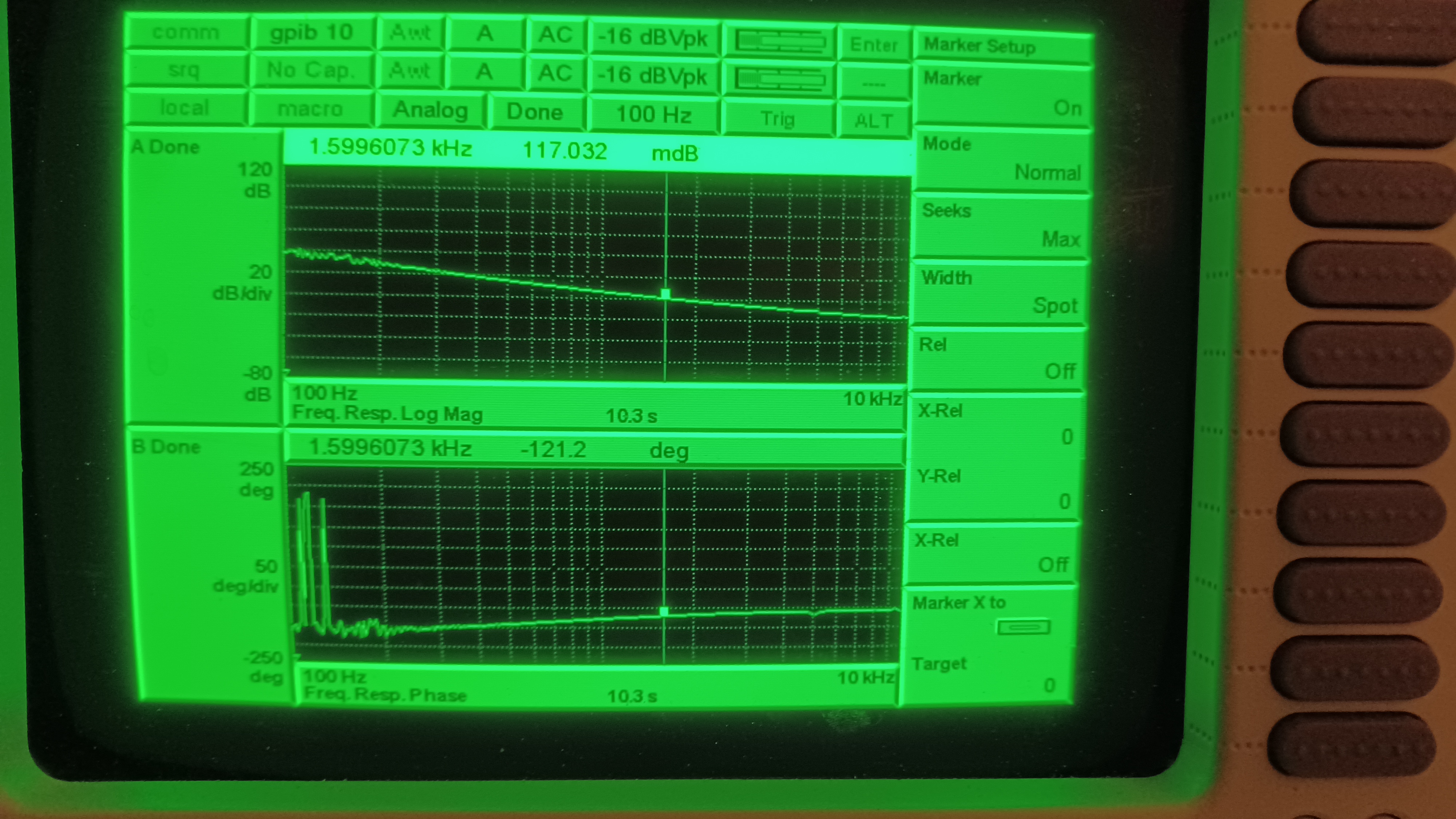
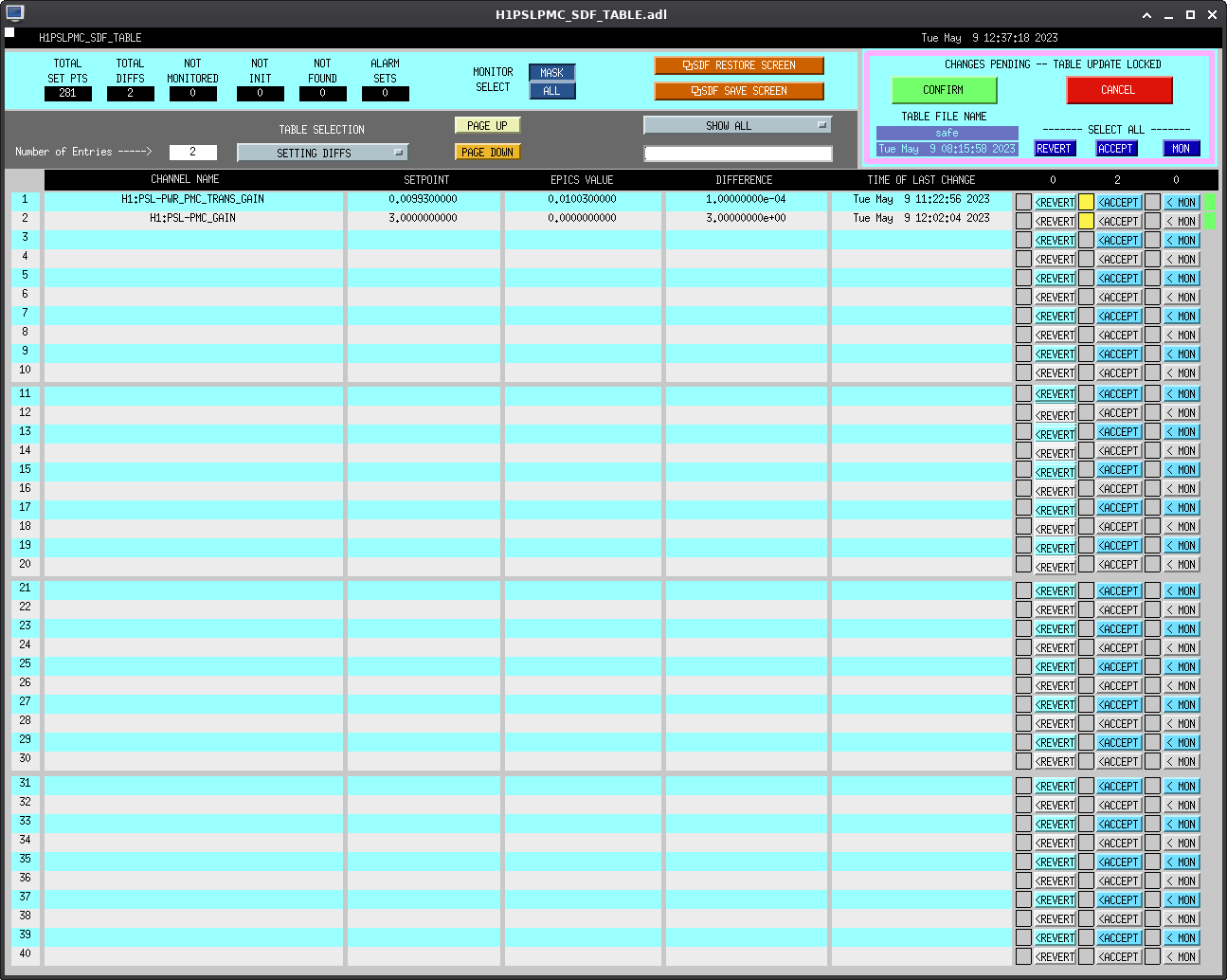
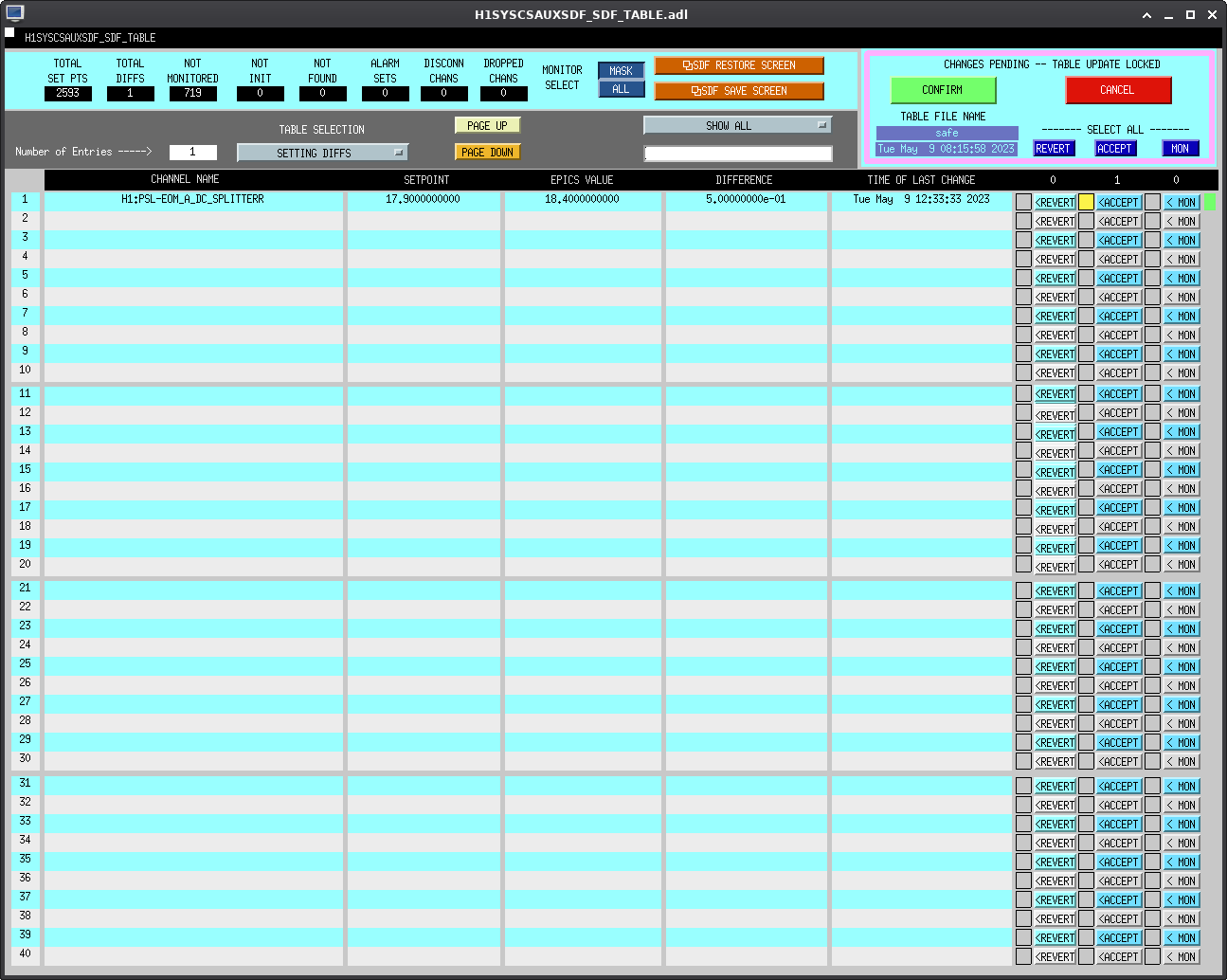
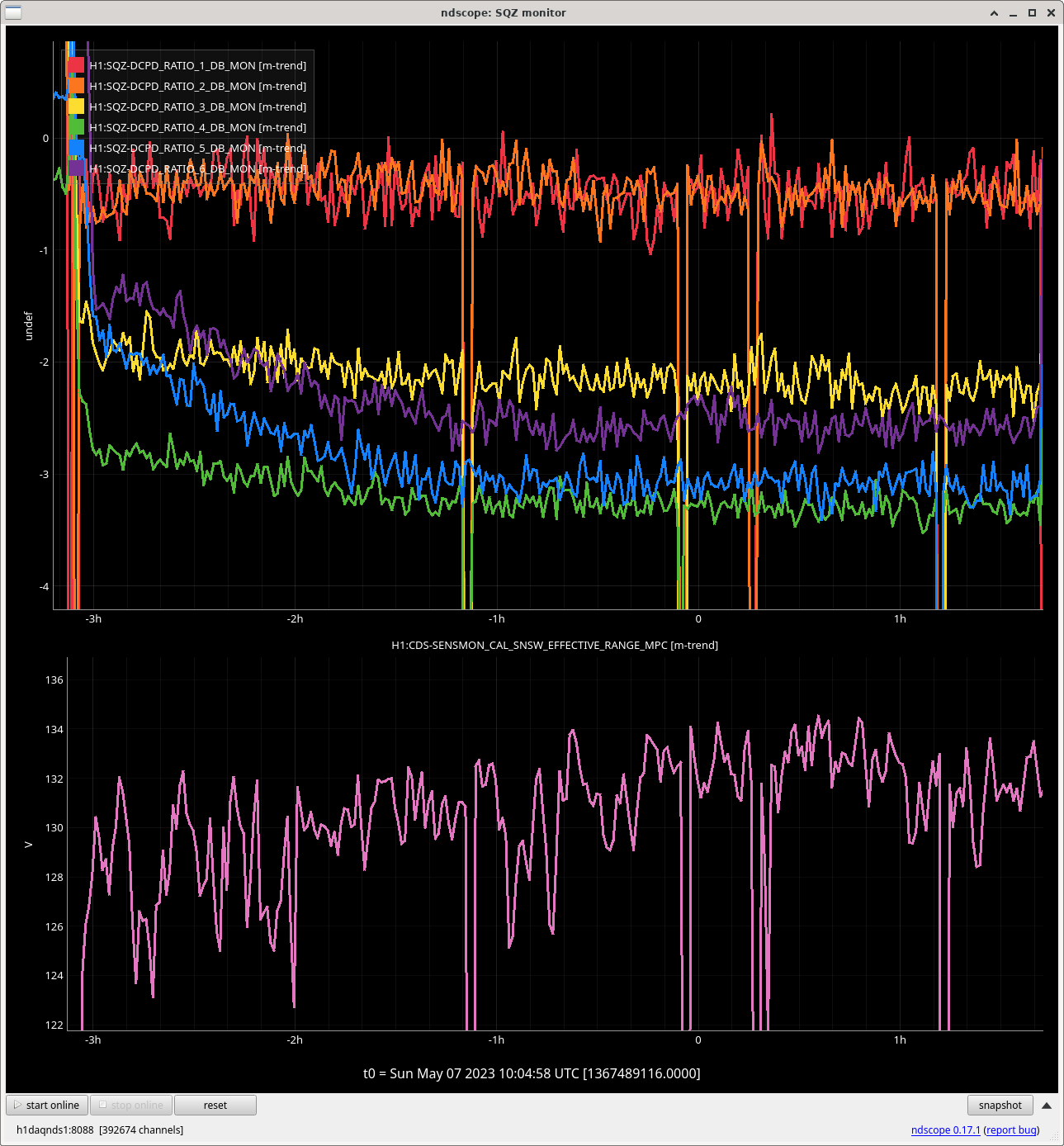
Due to the PMC oddness, we looked at the TF, and found the UGF at ~2kHz with ~60 degrees of phase margin. This is a little higher than we like (the new all-bolted PMC is supposed to have a UGF closer to 1kHz). We lowered the PMC gain slider from 3dB to 0dB, which gave us a UGF of ~1.6kHz with ~59 degrees of phase margin (see attached picture). To get closer to a 1kHz UGF we have to lower the light level on the PMC locking PD. As the maintenance window was over and it seemed to be happy where it was we did not do this; if things become unhappy at this operating point we can go back in and lower the locking PD light level. Back at the control room we recovered the FSS and recalibrated the EOM Out PD. Ryan tweaked the beam alignment into the RefCav which increased the TPD from 0.76V to 0.87V; we'll have to go back in and tweak the FSS beam path alignment to get the TPD higher. The ISS was re-engaged and its RefSignal adjusted until we had ~2.5% diffracted power (giving a RefSignal of -1.99V). All SDF diffs were accepted; Ryan has screenshots that he will post as a comment to this alog. We will monitor the PMC over the coming days to make sure all is well; it seemed pretty happy when we finished up. This completes WP 11164.
WP 11121
All site PEM microphones have been upgraded with a CCLD conditioning amplifier and pre-polarized microphone. New microphones are now powered off single power supplies set to 5V. Microphones were placed in same locations as old microphones.
The old H2 output HAM7 microphone is temporarily installed in the bier garden PEM area. Old HAM7 chamber has been removed. PEM group can decide on new location for microphone. Adrian Helmling-Cornell verified all microphones are working.
F. Clara, A. Helmling-Cornell
WP 11083
Cabling for the Magnetic Injection Coils complete. Locations for each coil listed below:
The injection signals are run from a PEM AI chassis to an audio amplifier. Amplifier is powered on/off by a Pulizzi (switchable AC power port). Currently the Corner Station Vertex and EX VEA units are not connected to a Pulizzi. Both amplifiers were left powered on with drive signal set to 0V. Pulizzi units should not be disconnected as we plan to run injections on Tuesday mornings. Pictures attached of two installations.
F. Clara, A. Helmling-Cornell
J. Kissel, T. Shaffer
While recovering the IFO, we noticed that the ASDs of the PCALX and PCALY on the front wall DARM_FOM looked odd and DIAG_MAIN reported issues with PCALY optical follower servo (OFS). Hearing that there was Beckhoff restarts at the end-stations today, we checked in with the PCAL screens. Indeed, a standard toggle of the OFS loop enable buttons (H1:CAL-PCAL{X,Y}_OPTICALFOLLOWERSERVOENABLE) needed after beckhoff work cleared the issue and the usual spectrum of calibration lines came back up as expected.
I have added sqz angle adjustments to the THERMALIZATION guardian that Gabriele made to servo the PRCL gain (alog 68948). SQZ angle will be adjusted from 165 to 145 degrees over the first 90 minutes of the IFO's lock. This is based on the SQZ Angle Adjustments tests in alog 69055.
In the SERVO_PRCL_GAIN state of the THERMALIZATION guardian, just before SQZ is injected, H1:SQZ-CLF_REFL_RF6_PHASE_PHASEDEG will be set to 20 degrees (SQZ_CHANGE) higher than nominal. Over 90 minutes (SQZ_THERM_TIME), the angle with be linearly taken to 145 degrees (sqzparams.SQZ_ANGLE). Adjustments to final sqz angle should be saved to /sqz/h1/guardian/sqzparams.py as SQZ_ANGLE and THERMALIZATION reloaded (only reload during lockloss).
Hope that this will increase H1 range at the start of the lock, if this isn't the case, we can revert these changes.
Due to a typo in the guardian code, I restarted the THERMALIZATION guardian so that the SERVO_PRCL_GAIN actually started 5 minutes later than it should have done for this lock.
Given the recent update of the SRCL offset to -290 this past week (69402), it looks like our ideal squeeze angle when thermalized has changed quite a bit from before, when Camilla found a good squeeze angle for that IFO configuration. Here are trends of rotating the sqz angle a bit, watching the 1.3kHz ADF line phase-rotate (oops, we should probably look at the ADF magnitude, ie the IQ_RMS, as well; that will tell us if we're "squeezing" at the ADF frequency), the sqz blrms, and the range. We will probably want to update the "thermalized" angle in sqzparams.py.
Many maintenance activities today, but they are now complete and we are starting to relock.
Jenne, Camilla, Naoki
The ADS error signals are the demodulated DARM control signals at dither frequency, which are not 0 even without the ADS lines. Since people sometimes get confused, we modified the camera guardian so that the ADS demodulation gain is turned off and the ADS error signals get 0 when the camera servo is used.
The daqd was restarted around 12:21 localtime.
F. Mera, M. Pirello
Replaced Aging Kepcos with upgraded supplies in H1-VDC-C2 CER Mezanine Power Rack. Racks affected:
H1-ISC-C3 +/-18V, +/-24V (all RF chassis)
H1-ISC-C2 +/-18V also H1-ISC-C1 uses this +/-18V, now documented. (Signals Chassis)
H1-ISC-C2 Slow Controls +24V (this is all beckhoff and acromag in ISC-C2 sans Corner 6 and Corner 2)
H1-SQZ-C1 Slow Controls & OMC IO Chassis +24V (Entire squeezer rack in CER)
We also found that Slow Controls Corner 6 & Corner 2 are powered by the IO Chassis ASC, LSC +24V supply, so these two did not go down during the swap.
Keywords: aging ageing