david.barker@LIGO.ORG - posted 10:09, Saturday 06 May 2023 (69381)
Sat CP1 Fill
Sat May 06 10:05:20 2023 INFO: Fill completed in 5min 19secs
Images attached to this report

Sat May 06 10:05:20 2023 INFO: Fill completed in 5min 19secs
TITLE: 05/06 Day Shift: 15:00-23:00 UTC (08:00-16:00 PST), all times posted in UTC
STATE of H1: Calibration
CURRENT ENVIRONMENT:
SEI_ENV state: CALM
Wind: 3mph Gusts, 1mph 5min avg
Primary useism: 0.01 μm/s
Secondary useism: 0.12 μm/s
QUICK SUMMARY:
- IFO was locked at NLN for 1:13 (acquired at 13:41 UTC)
- All observe SDFs are cleared, so I flipped the intention bit to OBSERVING @ 14:46 UTC
- CDS/SEI/FOM/DMs all look good
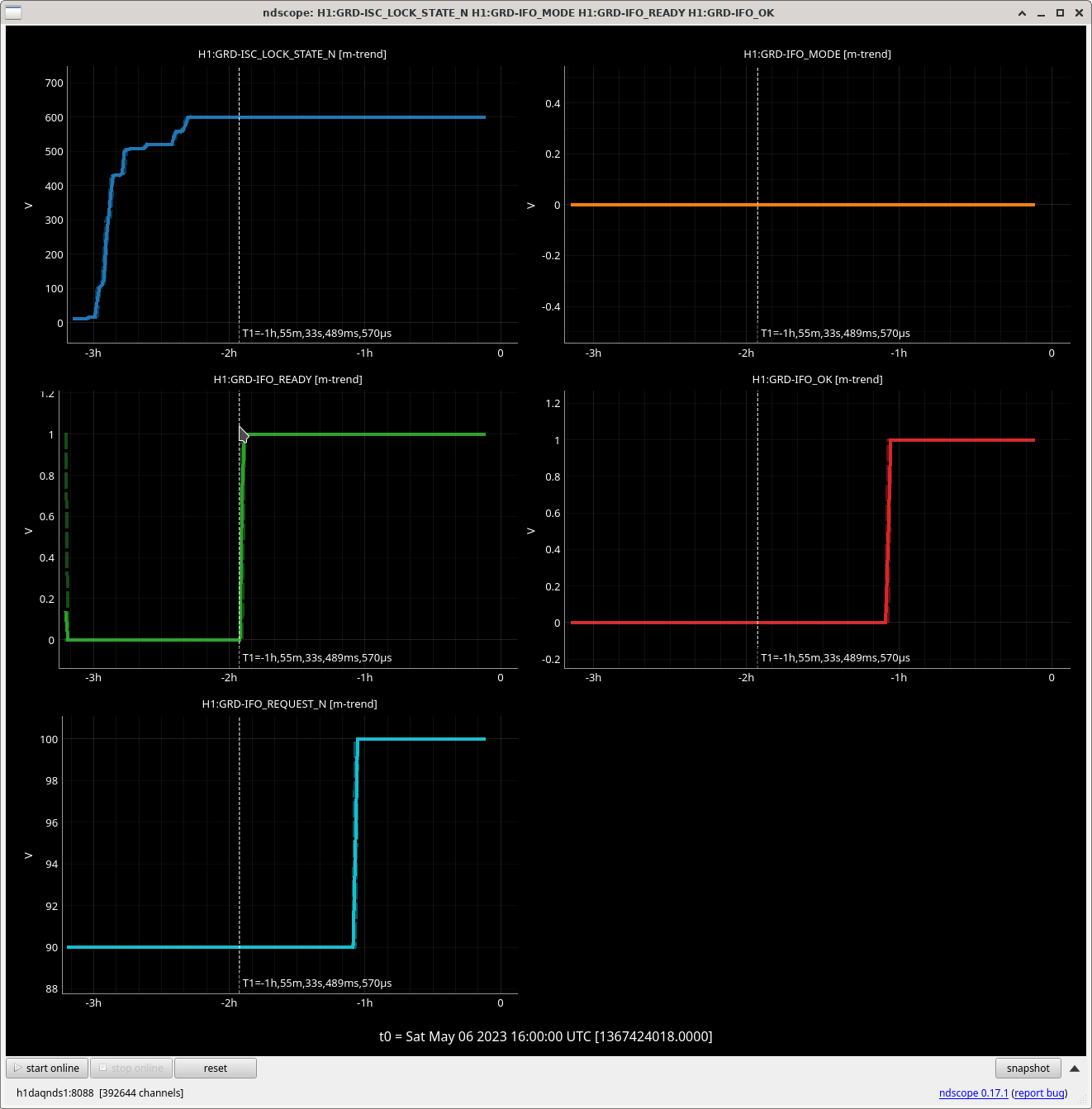
I was mistakenly under the impression that changing the IFO_MODE from Managed (1) to Auto (0) was enough for the IFO to change to OBSERVING (H1:GRD-IFO_OK = 1) once the IFO was READY. As the Guardian Overview shows, this is not enough, I also should have taken the Intention bit (H1:GRD-IFO_REQUEST) to OBSERVE for this to work. I didn't do that when I left Friday night as we were doing a calibration suite (69362) but I could have done as the IFO_READY flag would not have actually taken us to Observing until calibration was finished.
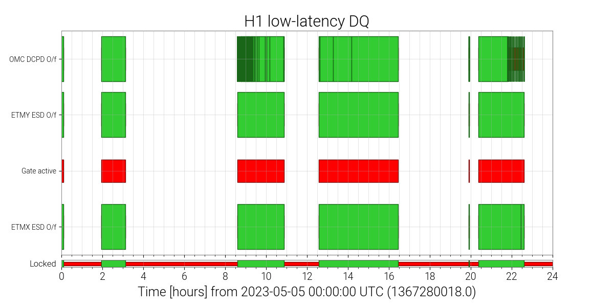
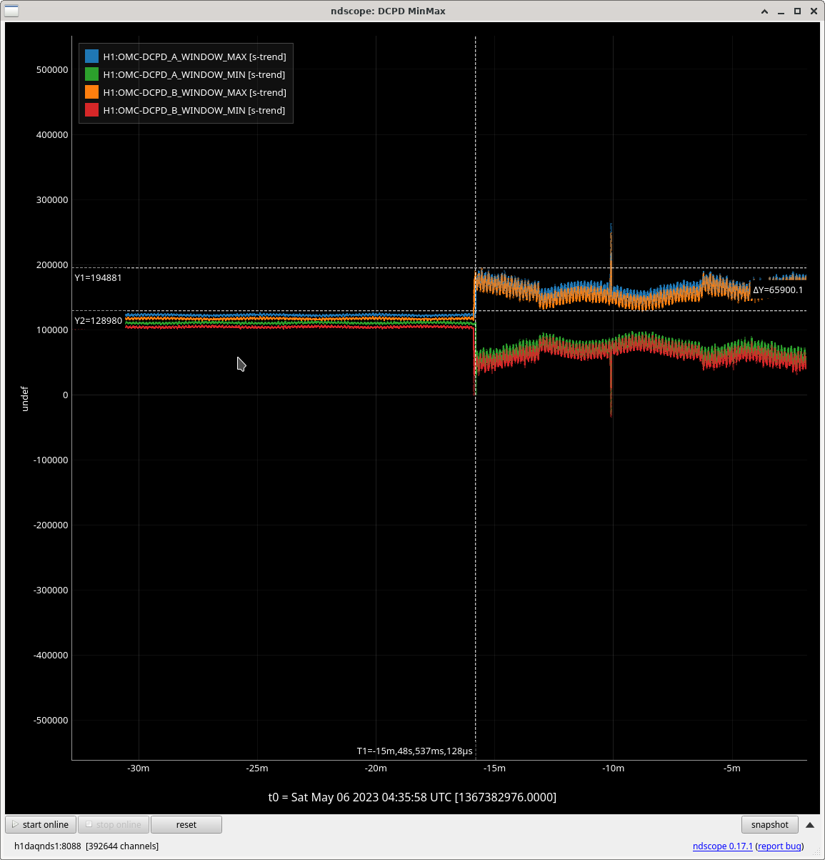
Tito Dal Canton from PyCBC reported that there are periods with many ADC overflows of the DCPD in the last few days. This is probably due to the increased DARM offset alog 69358. See attached plots of the DQ vector. There's no obvious effect on the spectrum or the glitchiness, so it must not be a severe overflow. But at least some of the searches are using this as a veto and aren't analysing the data.
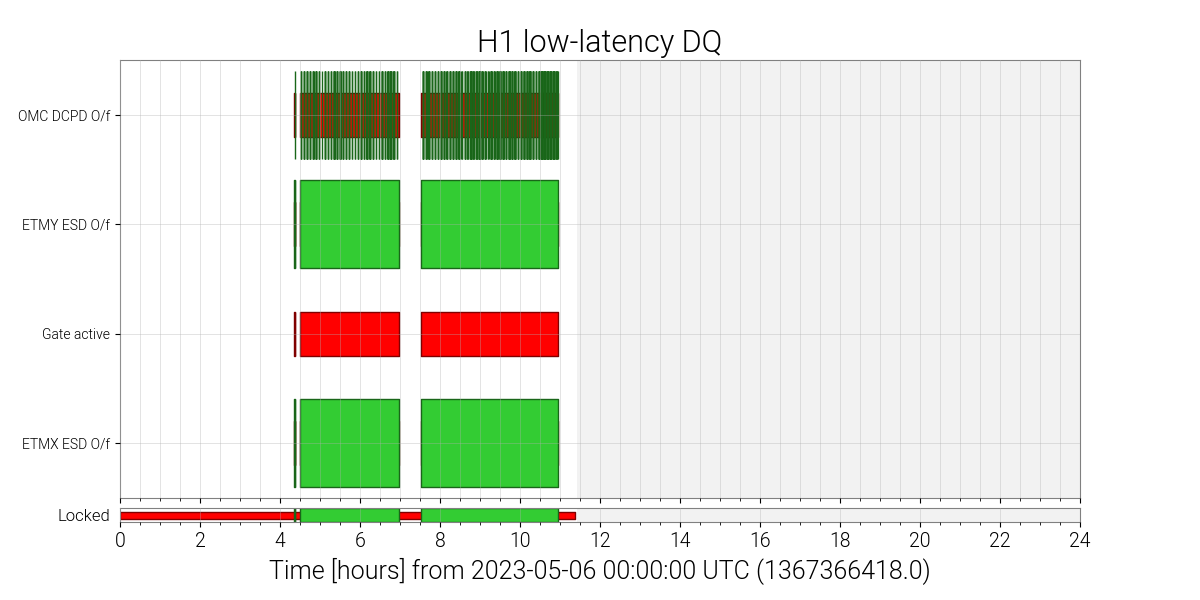
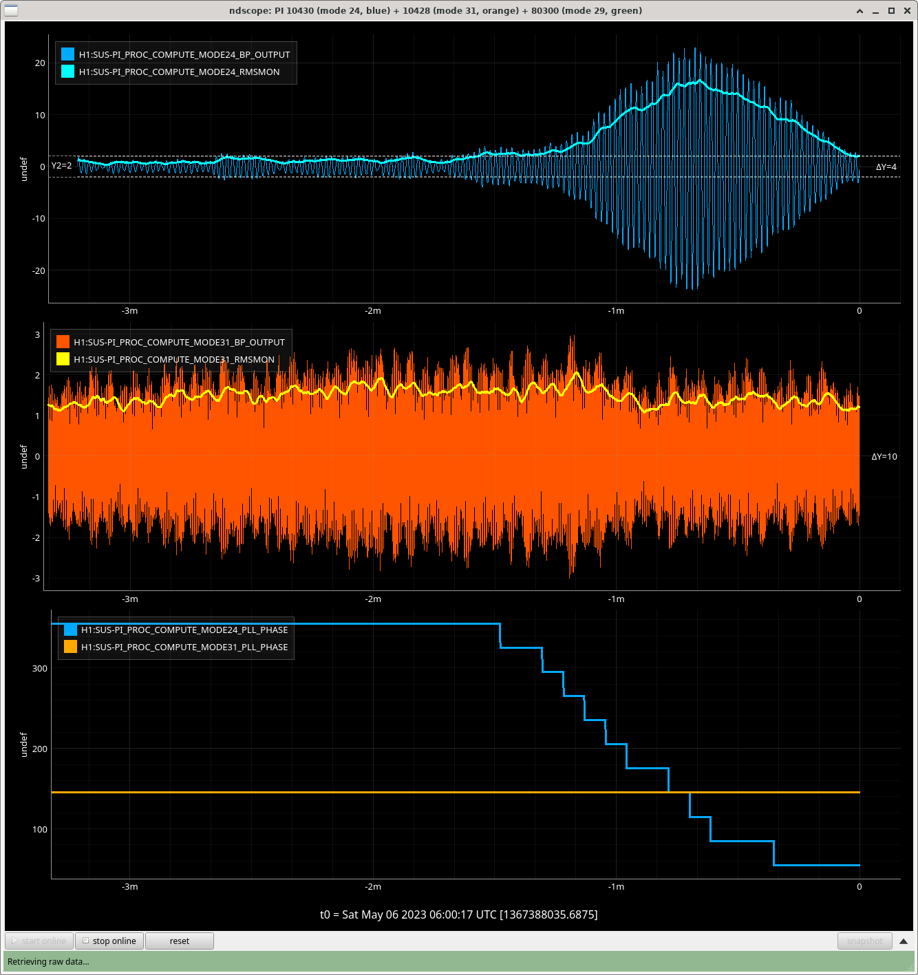
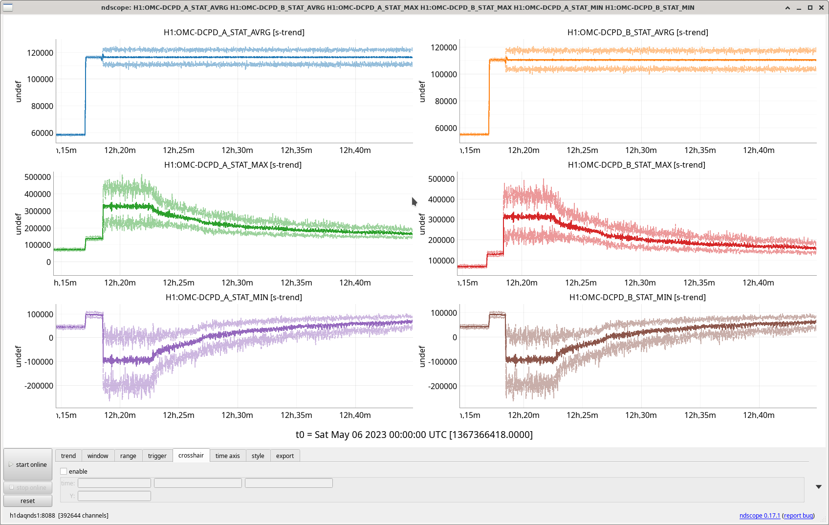
What is this triggered on? The attached plots show the DCPD min/max monitors for the same time. There are saturation events at the beginning (violin modes) and at the end of locks (lock loss), or during lock attempts, there are no saturations visible once the instruments have stabilized. One can also see some larger values during the most recent lock, which are still below saturation and which might be violin modes or parametric instabilities.
The plotted channels are 16 Hz EPICS channels that are caluclated in the front-end using data at the full converter rate (219 Hz). For each DCPD channel 4 18-bit ADC channels are getting summed to form a 20-bit word. Saturation happens once the sum channels reach ±219 counts. Since individual ADC offsets and gains could be slighlty different, a saturation monitor should propbably trigger around ±500,000.
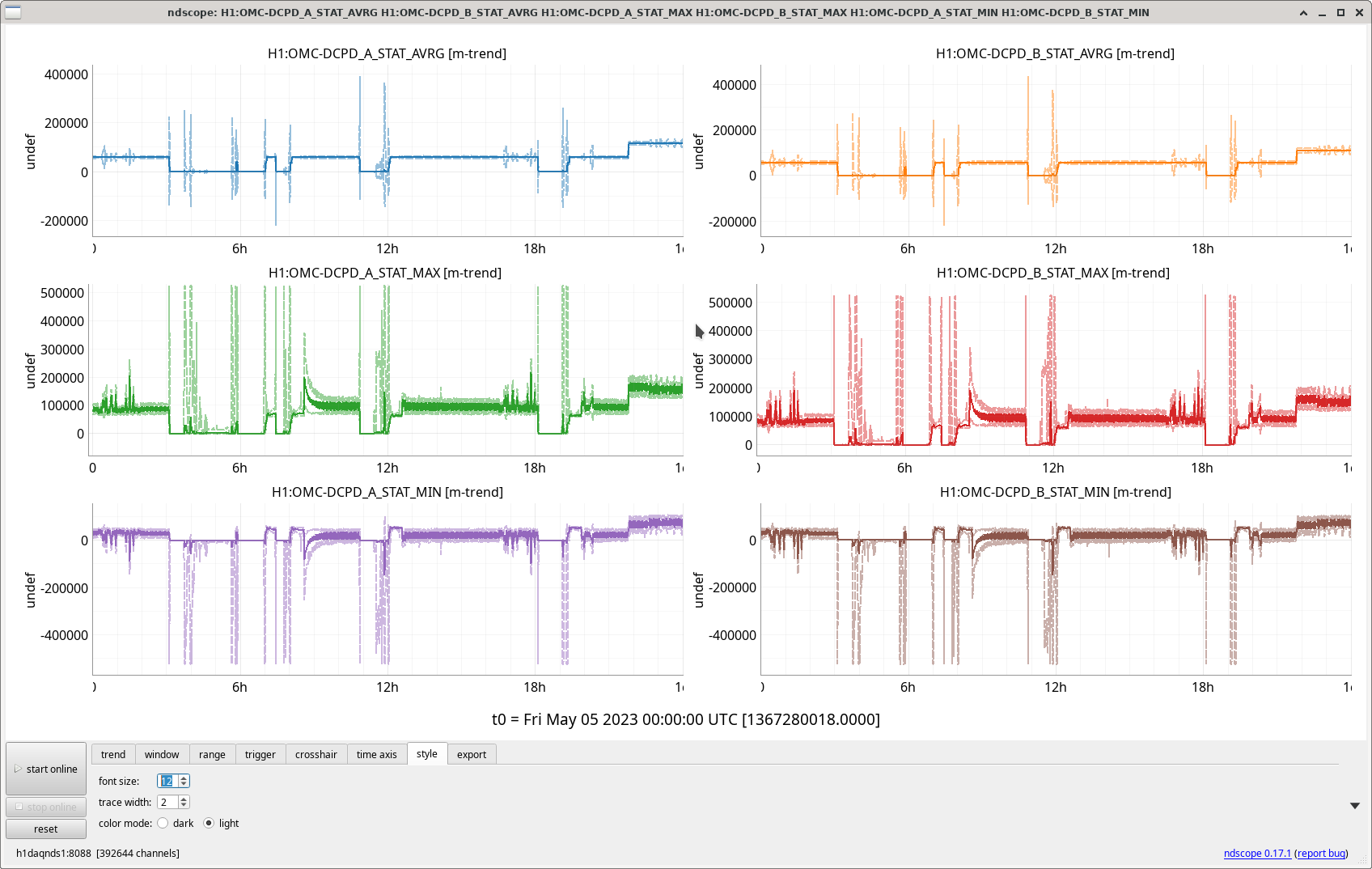
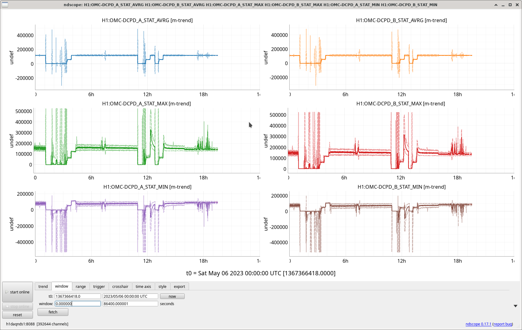
It will just be using the overflow channel calculated in the front end, H1:FEC-8_ADC_OVERFLOW_0_12 and 0_13 for DCPD A and B. The Simulink models that are exported show those as the only ADCs for the DCPDs, but they haven't been updated since 2022-07. Looking at the traces closely, the overflows do seem to be reported whenever STAT_MAX goes over ~2^17.
No sure what this indicates, seems wrong. Use H1:FEC-179_ADC_OVERFLOW_0_x with x = 0, 1, 4, 5, 8, 9, 12, and 13 instead.
Indeed, filling out Daniel's description:
This is one of the major changes to the detector for O4 -- the OMC DCPD signal processing chain is entirely different.

At LHO, we're reading out the same two in-vacuum OMC DCPDs with
    - A brand new low-noise transimpedance amplifier
    - A brand new whitening chassis
    - *no* analog anti-aliasing filter, but making 4 analog copies of the two input voltages
    - digitized with a brand new, lower noise, 18- (instead of 16 bit), 32 channel (instead of 16) ADC, sampled at 524 kHz, in an entirely new "segregated" IO chassis,
    - whose digital signal is created with a brand new real-time code Input-Output processing architecture -- whose DCUID is 179, hence H1:FEC-179_ADC_OVERFLOW_0_x with x = 0, 1, 4, 5, 8, 9, 12, and 13  -- that is "sampling" the 524 kHz voltage from the ADC at 65 kHz (i.e. grabbing 8 samples each 65 kHz clock cycle)
    - a new time-stamping system correlated with the DAQ, such that the data is *time stamped* as though its 5x 524 kHz clock cycles (i.e. 9.6 usec) behind all other data in the CDS architecture

After digitization, each channel's 4 copies are coherently summed, then divided by 4.0 in order to average the signal coherently across the 4 ADC channels (and thus improving the noise further by reducing the coherent digitization noise by sqrt(4)). Then, each averaged channel is
    - signal conditioned in new filter banks (running at 524 kHz)
        H1:OMC-DCPD_A0
        H1:OMC-DCPD_B0
    where the signal conditioning includes conversion from ADC counts back into milli-amps of current from the DCPDs via
        i. inversion of the measured transimpedance amplifier response
        ii. inversion of measured analog whitening response
        iii. inversion of the ADC "gain", now 2^18 ct / 40 V
        iv. two digital anti-aliasing filters, one for 524 kHz to 65 kHz, and one for 65 kHz to 16 kHz
and then that down-sampled, conditioned 524 kHz is shipped over inter-process communication to the old h1omc front-end model (with DCUID 8  -- i.e. H1:FEC-8_ADC_OVERFLOW), where it marries with identical 16 kHz digital infrastructure from O3 (save the *lack* of signal conditioning in 16 kHz the H1:OMC-DCPD_A and H1:OMC-DCPD_B filter banks because their function is now in the 524 kHz IOP model).

Please check out LHO:67644 for all the current digital version of the OMC DCPD channels.

Apologies that we've not yet had time to present this formally to all members of the collaboration repeatedly, as it was not until ~2 months ago that all this was settled. Information is stil scattered across aLOGs, to be gathered for review documentation.
And, naturally, only a portion of this is true at LLO. (They're still using a 65 kHZ analog AA filter, not using segregated IO chassis, and they're shipping from the 524 kHz IOP model to 16 kHz OMC model directly, rather than over IPC so their 524 kHz data is stamped as though it is 3 524 kHz clock cycles = 5.7 usec *ahead* of all the other CDS channels).

Note, all of these changes are "calibrated out" of the data stream, so down stream data analysis need not know *anything* about this, nor treat the calibrated data stream any different.
But -- *that* why the number to look at for ADC saturation has changed.
We have found an issue, with the calculation of the ADC limit in user models. User models are not accounting for 18 bit ADC values, and are erroneously reporting ADC overflows.

IOP models do have the proper logic. Can you switch the channel you use to check for overflows to the one provided by h1iopomc0?

Example:  H1:FEC-179_ADC_OVERFLOW_0_12 instead of  H1:FEC-8_ADC_OVERFLOW_0_12
LOCK#1
After the IFO was locked 5h13, we lost lock at 01:06UTC from ASC changes.
Elenna loaded a new MICH filter after the lockloss.
LOCK #2
Had a tough time relocking (later we noticed it seemed like CHECK_MICH_FRINGES moved the BS the wrong way at around 2:00UTC). This BS move made the DIFF beat note too low (-30) for LOCKING_ALS. I attempted an initial alignment. Couldn't get XAMR IR locked eso exited from initial alignment. Reverted BS pointing to before CHECK_MICH_FRINGES and touched PRM during ACQUIRE PRMI. Finally locked again. Inputting 76W at 03:45 UTC and at NLN at 04:20UTC. Delay due to OMC_WHITENING limited needed to be changed, alog69371.
Observing at 04:35UTC. SDFs accepted:
At 05:59UTC we had the 10.4Hz PI ring up (PI # 24), I was notified via verbalalarms and it and was successfully damped by the PI_DAMPING guardian, no intervention needed, Vicky's alog 69318 changes were good. See attached plot.
| Start Time | System | Name | Location | Lazer_Haz | Task | Time End |
|---|---|---|---|---|---|---|
| 21:39 | COMM | Jennie.Naoki.Vicky | CR | N |
DARM spring and SCRL offsets, SQZ, FC alignments. |
01:08 |
| 03:22 | SQZ | Naoki | CR | N | Injecting SQZ during locking | 04:22 |
| 6:45 | SQZ | Camilla | CR | N | SQZ angle adjustments | 6:52 |
| 6:55 | CAL | Louis | Remote | N | Calibration | eta 7:30 |


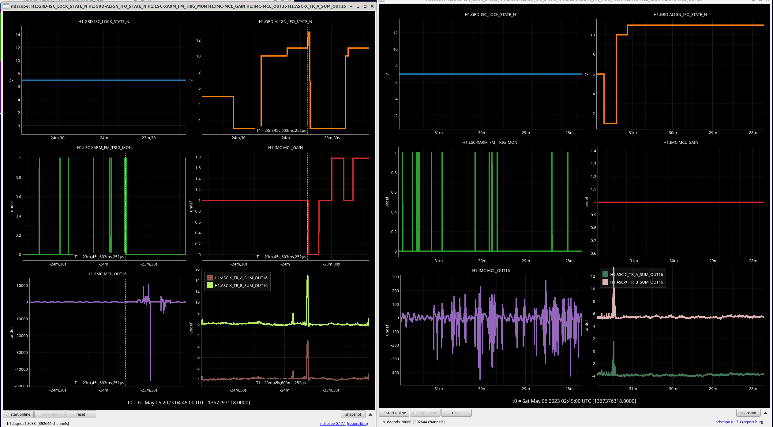
Notes on struggle Austin (69378) and I had for ACQUIRE_XARM_IR (state 11 of ALIGN_IFO) during INITIAL_ALIGNMENT. ALIGN_IFO is checking for LSC-XARM_FM_TRIG_MON to trigger and then it will turn off MCL gain and continue, since Friday evening this has triggered but not hed and ALIGN_IFO hasn't moved forward.
Plot attached comparing on the left a successful Initial alignment 2023/05/05 04:15 UTC verus on the right the failed alignment 2023/05/06 02:00 UTC. Light levels on the H1:ASC-X_TR_A_SUM_OUT16 while unlocked didn't get above their zero values.

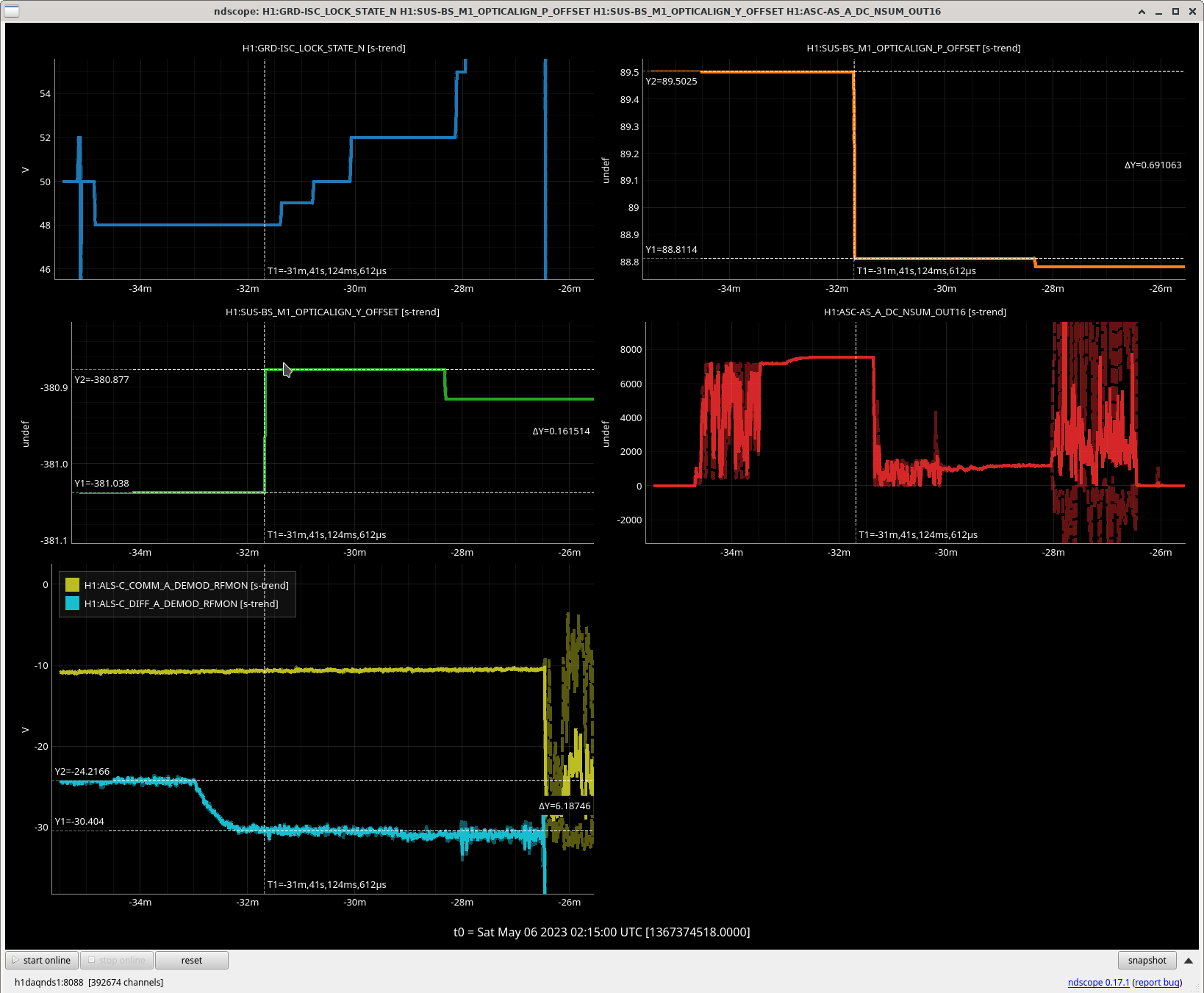
Attaching plot for time (2023/05/06 01:43 UTC) that CHECK_MICH_FRINGES reduced DIFF beatnote from -24 to -30. Not sure if this is expected.
Louis is starting Calibration Sensing Function as there has been a lot of IFO changes since Corey's alog 69345 measurements, list below. State of IFO before measurement attached.

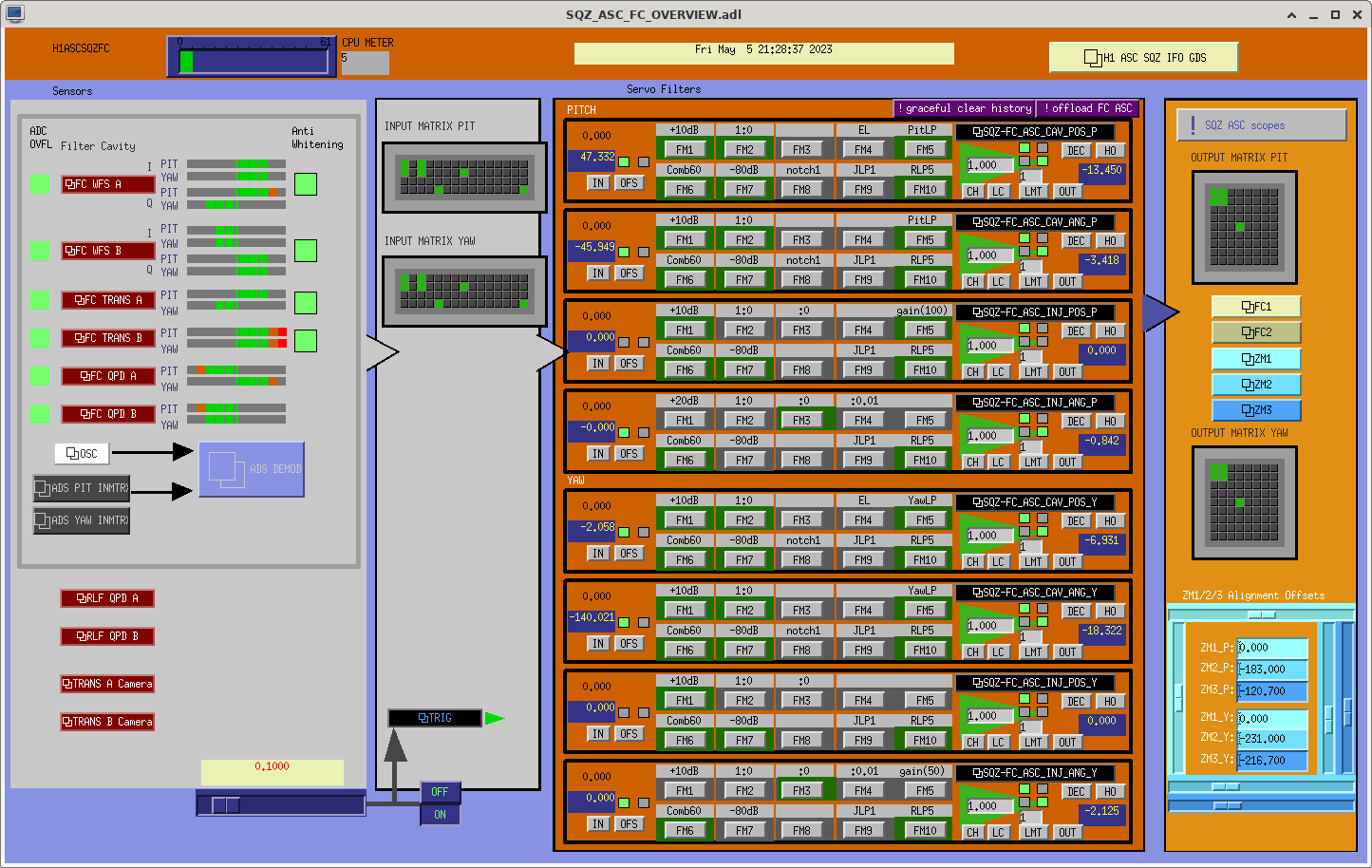
Naoki, Vicky
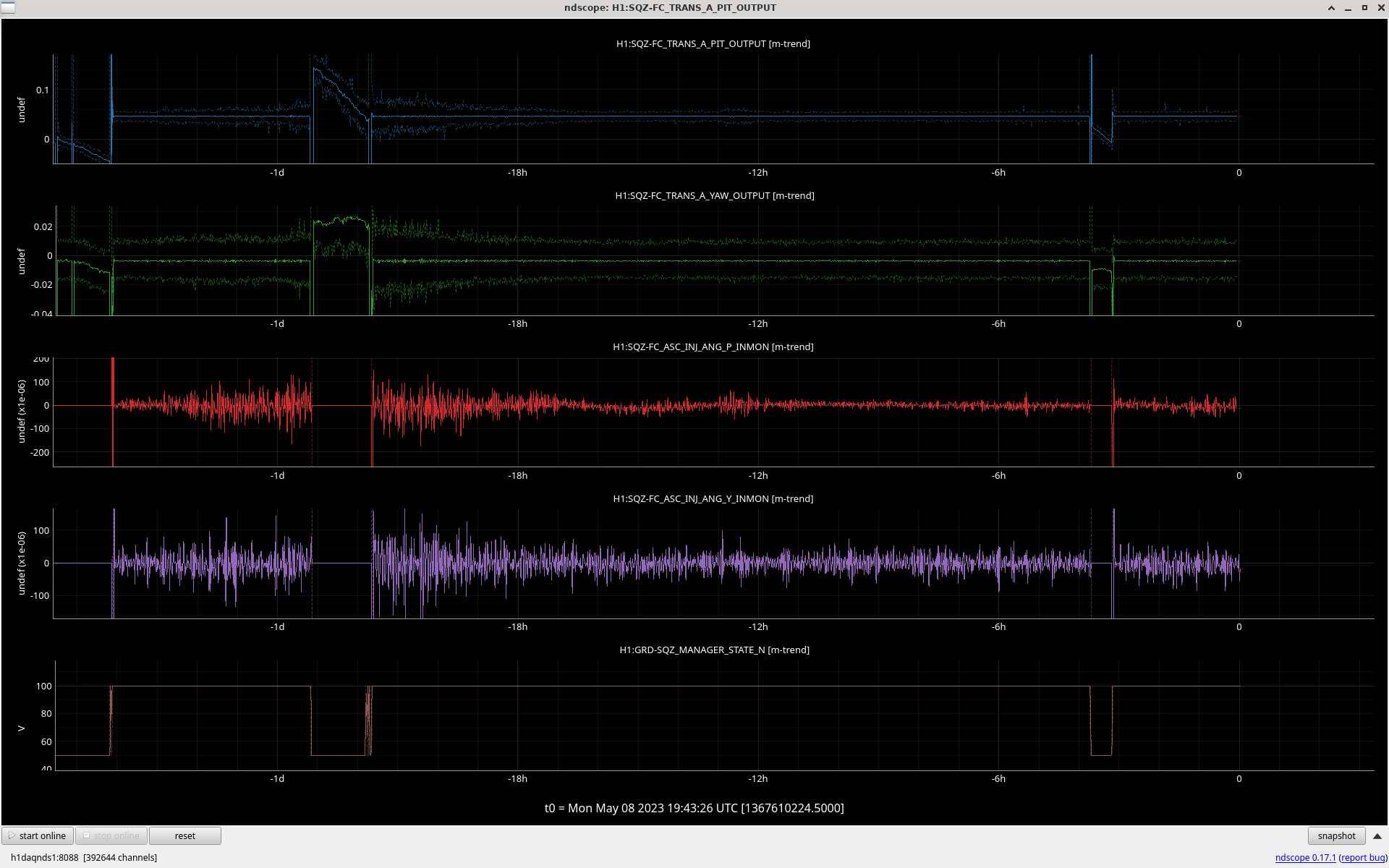
We successfully implemented the beam spot control with green QPD at FC trans by feeding back to ZM3 (Fig.1). The middle two are the green QPD P/Y signals and the bottom two are the error signals of the beam spot control P/Y. The cursors show the optimal green QPD offset for FC2 center which is decided in alog69338. After engaging the control, the green QPD signals settle to the optimal offset and the error signals become 0. The time scale of this control is ~1 min.
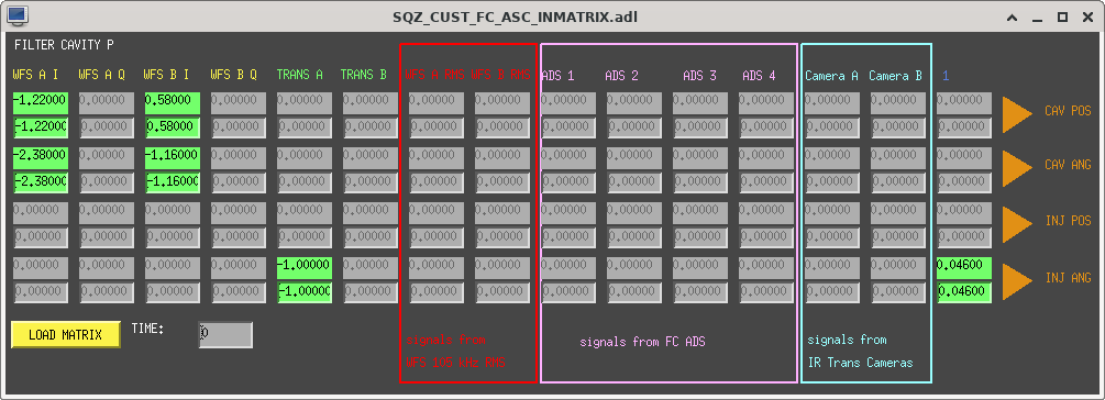
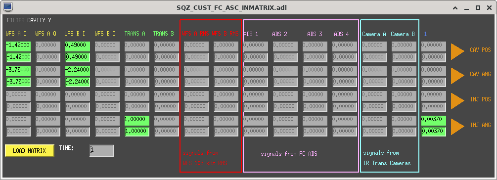
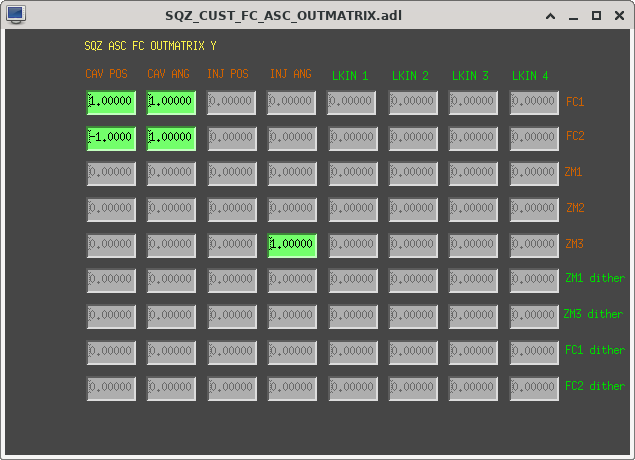
Fig. 2 shows the medm of FC ASC and Fig. 3-6 show the input/output matrix of FC ASC.
For stable FC green and IR lock with the beam spot control, we needed to clear history of filter bank of the beam spot control when the FC loses lock. Vicky added the clear history in down state of SQZ_FC guardian. The FDS with the beam spot control can be operated well by guardian.
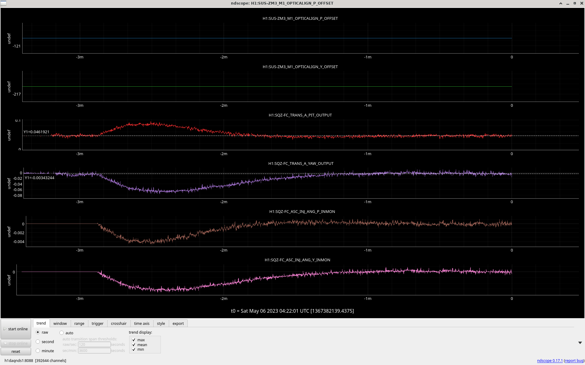

The attached figure shows the last 28 hours trend. The beam spot control works well when FC is working. I walked the green QPD offset by centering the FC2 when the beam spot control is engaged. The updated QPD offset is 0.07 for pitch and -0.0037 for yaw (yaw is not changed).
Elenna, Camilla, Vicky,
In our relock with OMC whitening changes (69350) PLUS a higher DCPD sum (69358), ICS lock kept us at OMC_WHITENING with the message "Violins are too high for whitening" but comparing violin levels (500Hz Violins on DARM were 4 x 10-16 m/Hz1/2 ) and DCPD levels in the last lock we realized we would be fine.
Elenna manually turned on the whitening and manualled us to NLN. Elenna updated the ISC_libary.check_for_violins_saturation(power='high') checker from her guesstimated factor of 6 (worked with higher whitening before higher DCPD offset) to a factor of 3.
DCPD signals with T-cursor when whitening turned on attached.
This one is cutting it pretty close!
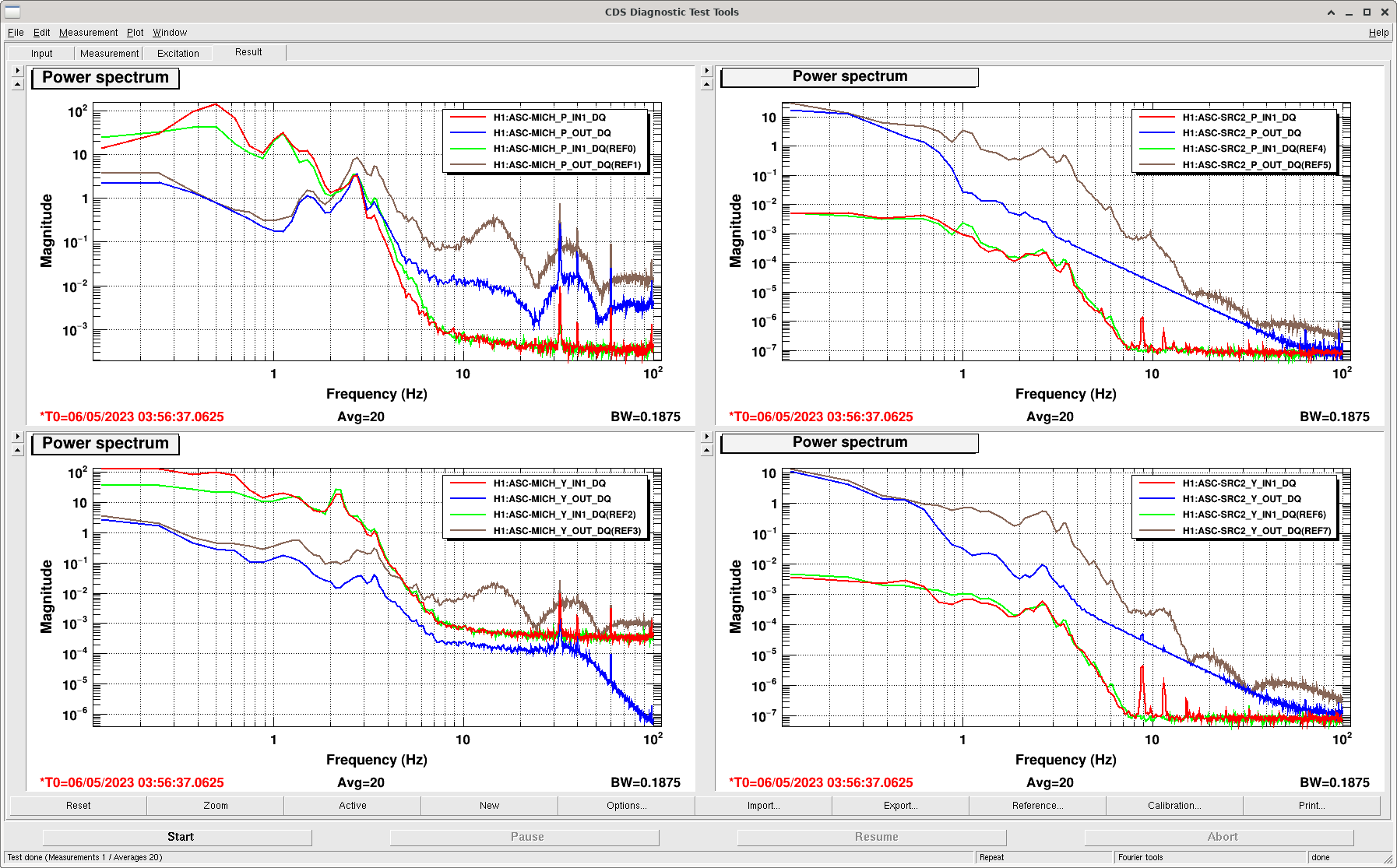
I have updated the SRC2 and MICH ASC controllers and cutoffs. The SRC2 P and Y controllers are the same that are applied to PRC2, with previous success (see 69108).
The MICH controllers are very different than before. I measured the MICH P olg recently and found it had a 2 Hz bandwidth, which seems high. The new controller reduces the bandwidth to 0.6 Hz. This allows us 24 dB less noise injection from 10-20 Hz. The MICH loops are now significant contributors to the ASC sub budget, so will be a significant improvement to ASC noise.
There is much more 0.5 Hz motion in the MICH P loop with this new controller engaged. The new loop has 16 dB of gain margin, so I increased the gain by 6 dB. There is still more 0.5 Hz motion than we are used to in MICH. It is not unstable. I will look into adjusting this loop design so we can improve the suppression at 0.5 Hz further but maintain some of the improved cutoff at 10 Hz. The MICH Y loop looks fine, although it also shows increased low frequency RMS.
All of these controllers are now guardianized. SRC2 is engaged in ENGAGE_ASC with the new controller and cutoff. The MICH loop is turned off briefly in OFFLOAD_DRMI to switch from AS 45 to AS 36, so I use that moment to switch over to the new controller and cutoff. I then increase the MICH P gain in PREP ASC to further suppress the 0.5 Hz motion.
In MICH P, FM7 now replaces FM8 and 10. In MICH Y, FM5 replaces FM7 and FM10. IN SRC2 P and Y, FM6 replaces FM7 and 9.
There is possibly small improvement in DARM between 10-20 Hz, but with all the other changes today, it is hard to tell.
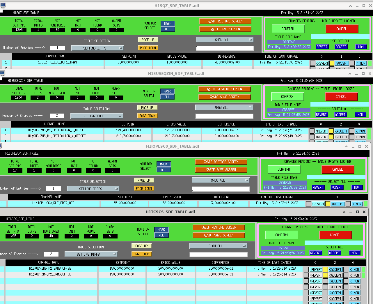
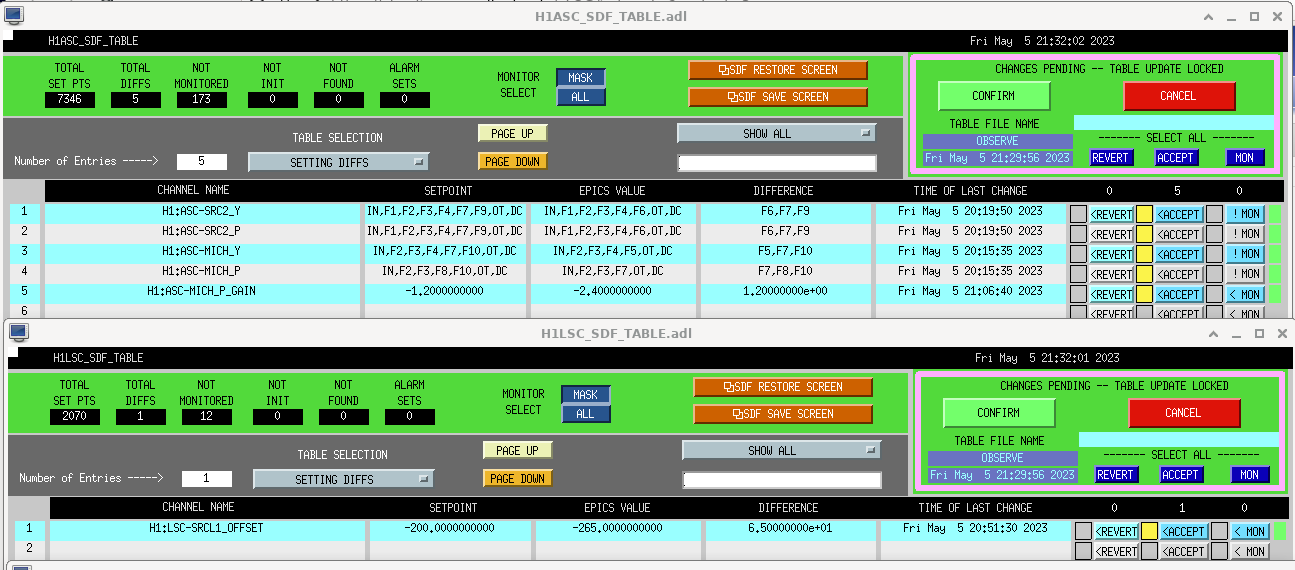
Attached screenshot of these changes accepted in sdf.
Vicky, Camilla.
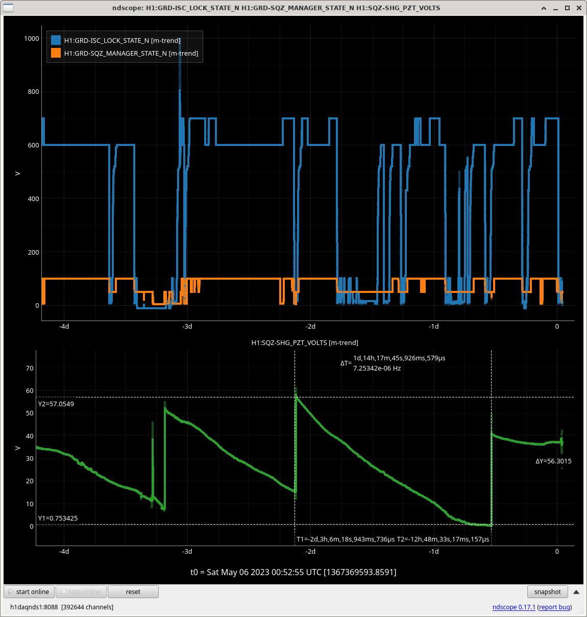
H1:SQZ-SHG_PZT_VOLTS is going from 55V to zero over ~40 hours, plot attached. In alog 68568 Vicky notes that when SHG PZT ran out of range, SQZ_MANAGER handles it fine, taking SQZ out of the IFO, relocking everything before re-injecting SQZ. But to minimize this happening during long locks we've added a checker in LOCK_SHG and SQZ_READY_IFO to check if H1:SQZ-SHG_PZT_VOLTS < 15, return LOCK_SHG and take the SQZ_SHG guardian to DOWN back to LOCKED, which puts the PZT voltage in the middle of it's range.
Jennie, Jenne, Vicky, Camilla
After setting the DARM offset to 40mA I took another set of SRC tuning measurements, where I changed the SRCL1 offset and measurement the sensing function at low frequencies with Craig's noise_recorder functions. Data folders and figure folders are listed in the table and the sensing function measurements for each are attached in order of detuning (whereas the table is in time order). The first measurement was done when we were around 2hr 51 mins thermalised and the -265 count measurement when we were 3hrs 52 mins into lock. Camilla and I picked out this offset as giving the flattest sensing function (ie. no detuning). I want to do some smoothing of the data tomorrow to make it clearer, however.
| SRCL1 OFFSET | DARM Injection Time | PCAL > DARM Time | DARM measurement | PCAL > DARM measurement | Data Folder | Figures Folder |
| -200 | 1367361681 | 1367361890 |
/ligo/gitcommon/noise_recorder/data/darm_noise/202305051541/darm_noise_srcl_src1_-200cts_40mA_more_POP_RF45_range-6_50_6_50_Hz_gps_start_1367361681.hdf5 |
/ligo/gitcommon/noise_recorder/data/darm_noise/202305051544/pcaly_srcl_src1_-200cts_40mA_more_POP_RF45_range-6_50_6_50_Hz_gps_start_1367361890.hdf5 | /ligo/gitcommon/noise_recorder/data/darm_noise/202305051541 | /ligo/gitcommon/noise_recorder/figures/darm_noise/202305051541 |
| -220 | 1367362508 | 1367362693 | /ligo/gitcommon/noise_recorder/data/darm_noise/202305051554/darm_noise_srcl_src1_-220cts_40mA_more_POP_RF45_range-6_50_6_50_Hz_gps_start_1367362508.hdf5 | /ligo/gitcommon/noise_recorder/data/darm_noise/202305051557/pcaly_srcl_src1_-220cts_40mA_more_POP_RF45_range-6_50_6_50_Hz_gps_start_1367362693.hdf5 |
/ligo/gitcommon/noise_recorder/data/darm_noise/202305051554 | /ligo/gitcommon/noise_recorder/figures/darm_noise/202305051554 |
| -300 | 1367363148 | 1367363333 | /ligo/gitcommon/noise_recorder/data/darm_noise/202305051605/darm_noise_srcl_src1_-300cts_40mA_more_POP_RF45_range-6_50_6_50_Hz_gps_start_1367363148.hdf5 | /ligo/gitcommon/noise_recorder/data/darm_noise/202305051608/pcaly_srcl_src1_-300cts_40mA_more_POP_RF45_range-6_50_6_50_Hz_gps_start_1367363333.hdf5 |
/ligo/gitcommon/noise_recorder/data/darm_noise/202305051605 | /ligo/gitcommon/noise_recorder/figures/darm_noise/202305051605 |
|
-350 |
1367364160 | 1367364348 | /ligo/gitcommon/noise_recorder/data/darm_noise/202305051622/darm_noise_srcl_src1_-350cts_40mA_more_POP_RF45_range-6_50_6_50_Hz_gps_start_1367364160.hdf5 |
/ligo/gitcommon/noise_recorder/data/darm_noise/202305051625/pcaly_srcl_src1_-350cts_40mA_more_POP_RF45_range-6_50_6_50_Hz_gps_start_1367364348.hdf5 |
/ligo/gitcommon/noise_recorder/data/darm_noise/202305051622 | /ligo/gitcommon/noise_recorder/figures/darm_noise/202305051622 |
| -265 | 1367365155 | 1367365406 | /ligo/gitcommon/noise_recorder/data/darm_noise/202305051638/darm_noise_srcl_src1_-265cts_40mA_more_POP_RF45_range-6_50_6_50_Hz_gps_start_1367365155.hdf5 | /ligo/gitcommon/noise_recorder/data/darm_noise/202305051643/pcaly_srcl_src1_-265cts_40mA_more_POP_RF45_range-6_50_6_50_Hz_gps_start_1367365406.hdf5 |
/ligo/gitcommon/noise_recorder/data/darm_noise/202305051638 | /ligo/gitcommon/noise_recorder/figures/darm_noise/202305051638 |
| -275 | 1367366250 | 1367366435 | /ligo/gitcommon/noise_recorder/data/darm_noise/202305051657/darm_noise_srcl_src1_-275cts_40mA_more_POP_RF45_range-6_50_6_50_Hz_gps_start_1367366250.hdf | /ligo/gitcommon/noise_recorder/data/darm_noise/202305051700/pcaly_srcl_src1_-275cts_40mA_more_POP_RF45_range-6_50_6_50_Hz_gps_start_1367366435.hdf5 | /ligo/gitcommon/noise_recorder/data/darm_noise/202305051657 | /ligo/gitcommon/noise_recorder/figures/darm_noise/202305051657 |
| -290 | 1367367974 | 1367368175 | /ligo/gitcommon/noise_recorder/data/darm_noise/202305051725/darm_noise_srcl_src1_-290cts_40mA_more_POP_RF45_range-6_50_6_50_Hz_gps_start_1367367974.hdf5 | /ligo/gitcommon/noise_recorder/data/darm_noise/202305051729/pcaly_srcl_src1_-290cts_40mA_more_POP_RF45_range-6_50_6_50_Hz_gps_start_1367368175.hdf5 | /ligo/gitcommon/noise_recorder/data/darm_noise/202305051725 | /ligo/gitcommon/noise_recorder/figures/darm_noise/202305051725 |
To run the DARM injection use noise_recorder/code/darm_noise_injection_caller.py
To run the PCAL to DARM measurement use noise_recorder/code/pcal_noise_injection_caller.py
To process use noise_recorder/code/darm_sensing_function_processor.py
To plot all sensing functions use noise_recorder/code/darm_sensing_spring_comparison.py, which is the png attached.
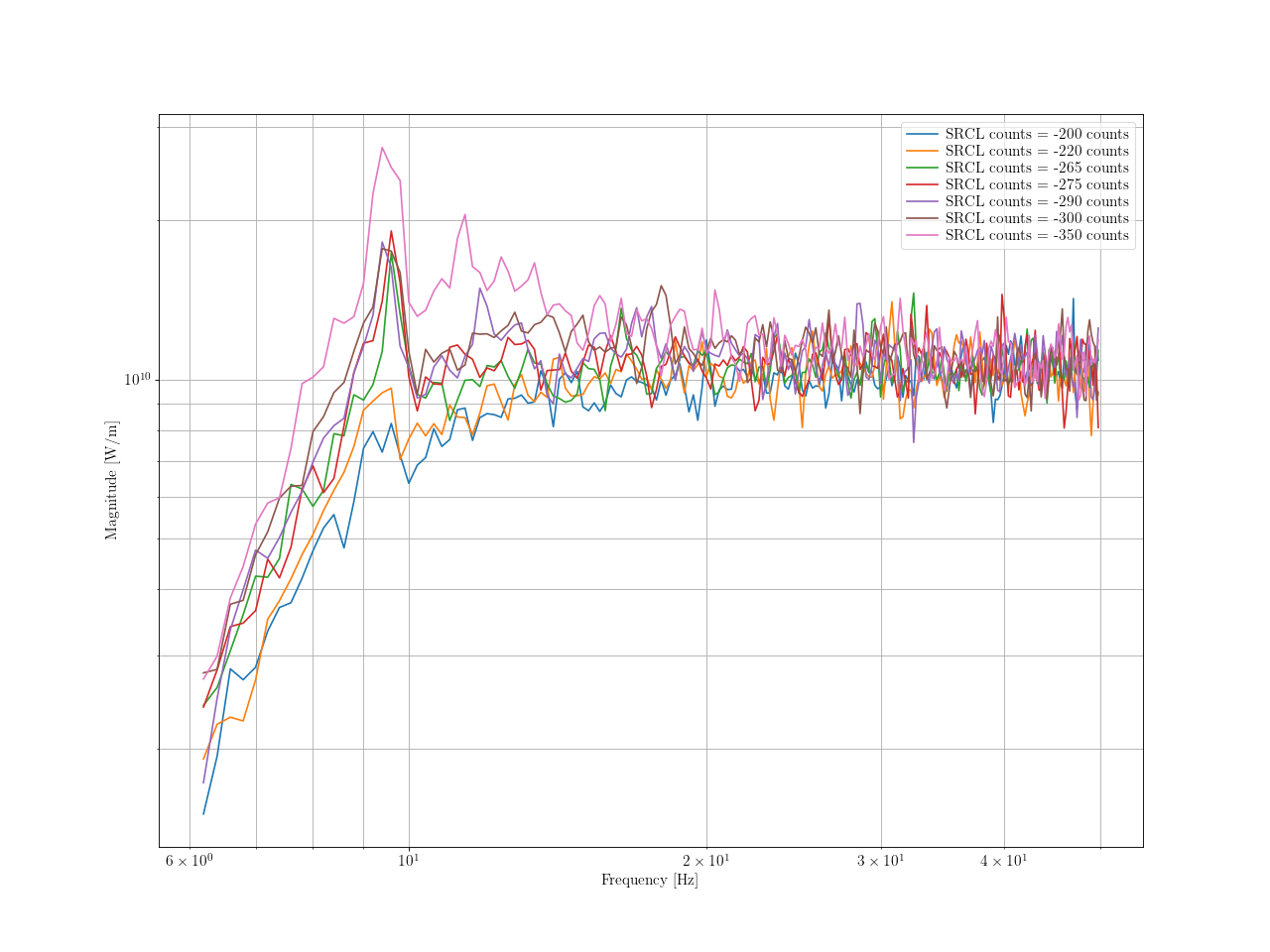
Elenna added this -265 offset to lscparams.py and I accepted in sdf. See attached.

Jennie, Naoki, Jenne, Elenna, Vicky
We took more measurements of 40mA vs. 20mA on the OMC SUM DCPD (that is, the DARM offset).
This is because our previous measurements did not correct DARM by the calibration at high frequencies, as the PCAL > DARM broadband transfer functions had low coherence at these frequencies.
The technique above 500Hz is thus to take a DARM ASD spectra and correct it by the peak height of the 1083 Hz PCAL line.
Measurement 1:
21:16:43 UTC
20mA (in OBS), so squeezing injected.
Ref0
Measurement 2:
21:38:42 UTC
20mA (IN COMMISSIONING), no squeezing.
Ref1
Measurement 3:
21:52:24 UTC
40 mA (IN COMMISSIONING), no squeezing.
Ref2
Measurement 4:
22:08:09 UTC
40mA (IN COMMISSIONING), squeezing injected.
Ref3
The measurements are saved in /ligo/home/jennifer.wright/git/DARM_offset/2023-05-05_2114UTC_H1_DARMSPEC.xml.
Attached are the scaled spectra (courtesy of Jenne).
Since the noise looks lower between 40mA no squeeze(brown) and 20mA no squeeze (green), we will go with this offset.
We are not sure why the 40mA, squeezer on trace looks so bad at low frequencies. There's not a way for the homodyne angle to produce the given change in the squeezing blue/pink traces, so that is likely the effect of something else on the squeezing. The most relevant comparison should be the no-squeezed DARM traces at different homodyne angles, green vs. brown.
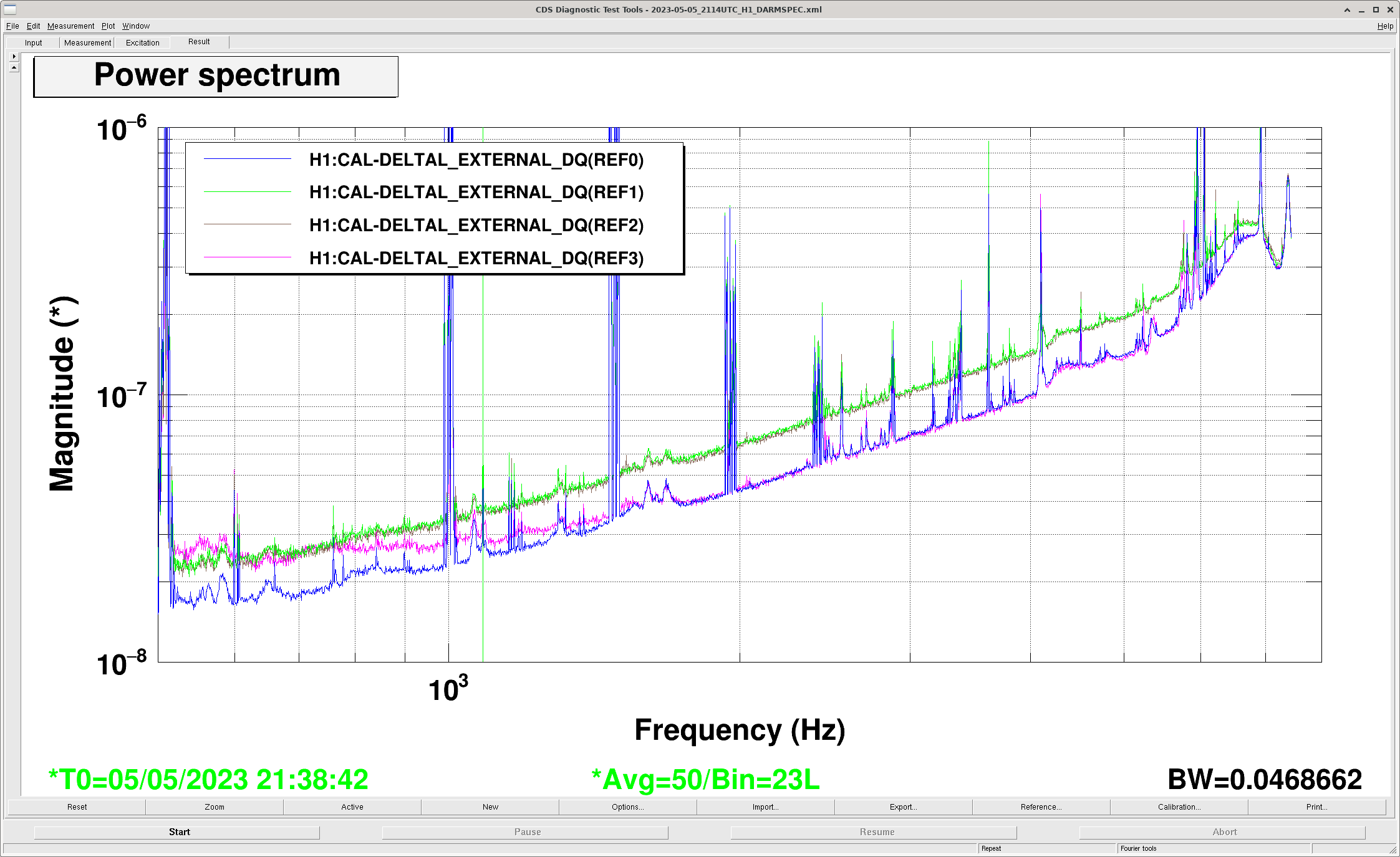
The pink trace, particularly when you look all the way to low frequency (not shown in this plot), includes a glitch time in it. Not a big deal, since the thing we were looking at here was a lot of the high frequency portion, where the glitch does not seem to be present.
After the IFO was locked 5h13, we lost lock at 01:06UTC from ASC changes. Had a tough time relocking (seemed like CHECK_MICH_FRINGES moved the BS the wrong way..) but now past ENGAGE_ASC_FOR_FULL_IFO.
Daniel Nutsinee
Added a new ADF OSC screen to the ADF overview.

While testing the "new" feature, the oscillator got stuck with nan outputs, meaning we no longer can use the ADF until we restart the h1sqz model. Dah.
With the DARM offset moving to 40mA total DCPD photocurrent (69358), this should correspond to an IFO readout angle of about -12 degrees, given the 1.7mA contrast defect (69361).
Using Craig's calculation of the homodyne / readout angle (65000), as a function of DCPD power level for a 1.7 mW of junk light (68859, 69361),
total_dcpd_light = 20 #mA # total dcpd mA level
contrast_defect = 1.7 #mA # this is a recently measured value
darm_offset_power = total_dcpd_light - contrast_defect
homodyne_angle = np.arctan2(np.sqrt(contrast_defect), np.sqrt(darm_offset_power)) #radians
homodyne_angle*180/np.pi #degrees
Here's the resulting homodyne angle for various DCPD powers:
| total dcpd light (mA) | homodyne angle (degrees), upper limit |
| 20 | -17.0 |
| 30 | -13.8 |
| 40 | -11.9 |
Attached here are some gifs of gwinc-calculated quantum noise for DARM with NO squeezing, rotating through some homodyne angles. The following NO-SQZ GPS times were used:

J. Betzwieser, D. Bhattacharjee, J. Kissel, R. Savage

Executive summary: More changes to calibration lines in order to commission the best answer out of the PCALXY comparison.

Based on the systems level compromises discussed on Friday last week about having the PCALX contribution to the PCALXY comparison right next to the 410.3 Hz PCALY line that's used for TDCFs (LHO:69175), I moved the PCALX comparison line from 410.2 Hz (0.1 Hz below 410.3 Hz) to 409.8 Hz (0.5 Hz below 410.3 Hz). LHO:69303.

After looking at the results from that move to 409.8 Hz, Joe, Rick, and Dripta re-discovered that there's a notch in the DARM loop at 410.3 Hz (see LHO:48530), which is a relatively wide elliptic bandstop (whose boundaries are 409.4 and 411.2 Hz, i.e. 410.3 +/- 0.9 Hz). That means the frequency response change of IFO's response function, C / (1 + G), is changing quite rapidly between the two 410.3 and 409.8 Hz frequencies. *That* means that the traditional, easy, side-by-side PCALXY comparison of lines to arrive at a ratio of amplitudes -- which assumes that the response function ratio isn't changing between frequencies -- becomes harder, and loop model dependent.

As such, yesterday, Joe, Rick, and Dripta got together and posted the proposal outlined last night LHO:69331, to move the lines that inform the PCALXY comparison entirely away from 410.3 Hz, such that the comparison is between
     H1:CAL-PCALX_PCALOSC8_OSC_FREQ    283.91       Already present as a "Systematic Error" line, but now louder, increasing amplitude from 200 to 2000 cts.
     H1:CAL-PCALY_PCALOSC4_OSC_FREQ    284.01       New PCALY line dedicated to this test, set with an amplitude of 1430 cts

I've implemented their proposal at of 2023-05-05 20:00 UTC.

Knock-on effects:
    - Because there's a new line on PCALY, I wanted to check whether we still have enough OFS range to drive the temporary, ER15 "thermalization" lines, driven by the CAL_AWG_LINES guardian. We do, so we're good there.
    - The new addition of 284.01 Hz PCALY *may* impact (bias) the demodulation (answer) of the 283.91 Hz PCALX systematic error line, given that that line's front-end DEMOD still uses a +/- 0.1 Hz wide SIG band pass, and 0.1 Hz corner frequency low pass, i.e. a 10 second FFT.
    - Because the systematic Error line is much louder, and has a new companion, equally loud "next door," the CW searches may be more likely to complain about sidebands and non-linearities not subtracted out.
    - Because I'm using a new PCALY oscillator, I need to double check that the GDS pipeline still safely subtracts this out in the GDS-CALIB_STRAIN_NOLINES channel.
    - This renders the DEMOD10 PCALX non-functional, since it's stuck demodulating the 409.8 Hz PCALX line that isn't there. Ideally, we'd convert PCALX DEMOD 10 to watching the new 284.01 Hz PCALY line, but that would require a front-end code change. Eventually, once we're done the 24.5 Hz PCALY thermalization line, then we can switch that PCALY DEMOD 4 over to using that.

Things that need to change in order to accommodate this move:
    (1) Accepted new oscillator settings in h1calex and h1caley SDF systems.
    (2) Modified the pydarm_H1.ini parameter file which now is up to version marked by git hash 156230c7. Parameters cal_line_cmp_pcalx_frequency and cal_line_cmp_pcaly_frequency have changed.
    (3) Pushed new DARM_ERR / PCAL and DELTAL / PCAL EPICs records at these line frequencies with the updated parameter file, using the command
        $ pydarm export --push --epics-only --model /ligo/groups/cal/H1/ifo/pydarm_H1.ini
    (4) Accepted them in h1calcs SDF.

Rick said he's going to take care of modifying the DEMOD SIG and low pass filters for the X Y comparisons as he needs.

Here's the latest list of calibration lines:
Freq (Hz)   Actuator               Purpose                      Channel that defines Freq             Since O3
15.6        ETMX UIM (L1) SUS      \kappa_UIM excitation        H1:SUS-ETMY_L1_CAL_LINE_FREQ          Amplitude Change on Apr 2023 (LHO:68289)
16.4        ETMX PUM (L2) SUS      \kappa_PUM excitation        H1:SUS-ETMY_L2_CAL_LINE_FREQ          Amplitude Change on Apr 2023 (LHO:68289)
17.1        PCALY                  actuator kappa reference     H1:CAL-PCALY_PCALOSC1_OSC_FREQ        Amplitude Change on Apr 2023 (LHO:68289)
17.6        ETMX TST (L3) SUS      \kappa_TST excitation        H1:SUS-ETMY_L3_CAL_LINE_FREQ          Amplitude Change on Apr 2023 (LHO:68289)
33.43       PCALX                  Systematic error lines       H1:CAL-PCALX_PCALOSC4_OSC_FREQ        New since Jul 2022 (LHO:64214, LHO:66268)
53.67         |                        |                        H1:CAL-PCALX_PCALOSC5_OSC_FREQ        Frequency Change on Apr 2023 (LHO:68289)
77.73         |                        |                        H1:CAL-PCALX_PCALOSC6_OSC_FREQ        New since Jul 2022 (LHO:64214, LHO:66268)
102.13        |                        |                        H1:CAL-PCALX_PCALOSC7_OSC_FREQ           |
283.91        V                        V                        H1:CAL-PCALX_PCALOSC8_OSC_FREQ           V
284.01      PCALY                  PCALXY comparison            H1:CAL-PCALY_PCALOSC4_OSC_FREQ        TURNED ON THIS ALOG
 ----       PCALX                  PCALXY comparison            H1:CAL-PCALX_PCALOSC2_OSC_FREQ        TURNED OFF THIS ALOG
410.3       PCALY                  f_cc and kappa_C             H1:CAL-PCALY_PCALOSC2_OSC_FREQ        No Change
1083.7      PCALY                  f_cc and kappa_C monitor     H1:CAL-PCALY_PCALOSC3_OSC_FREQ        No Change
n*500+1.3   PCALX                  Systematic error lines       H1:CAL-PCALX_PCALOSC1_OSC_FREQ        No Change (n=[2,3,4,5,6,7,8])
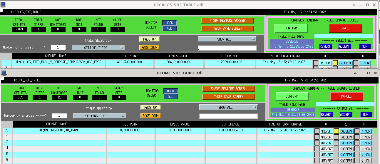
Accepted the new value of 284.01 for H1:CAL-CS_TDEP_PCAL_Y_COMPARE_COMPARISON_OSC_FREQ in sdf, screenshot attached.
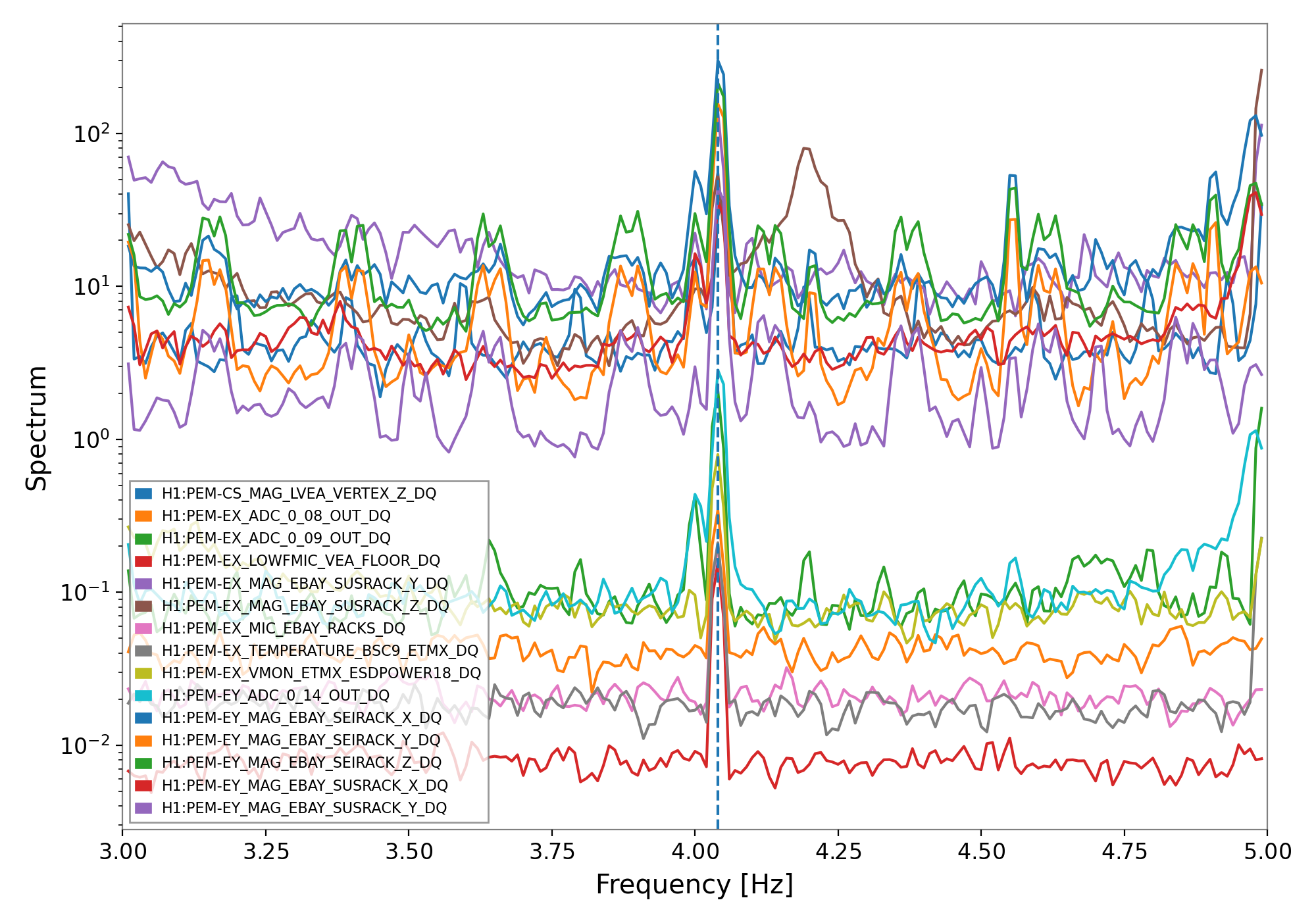
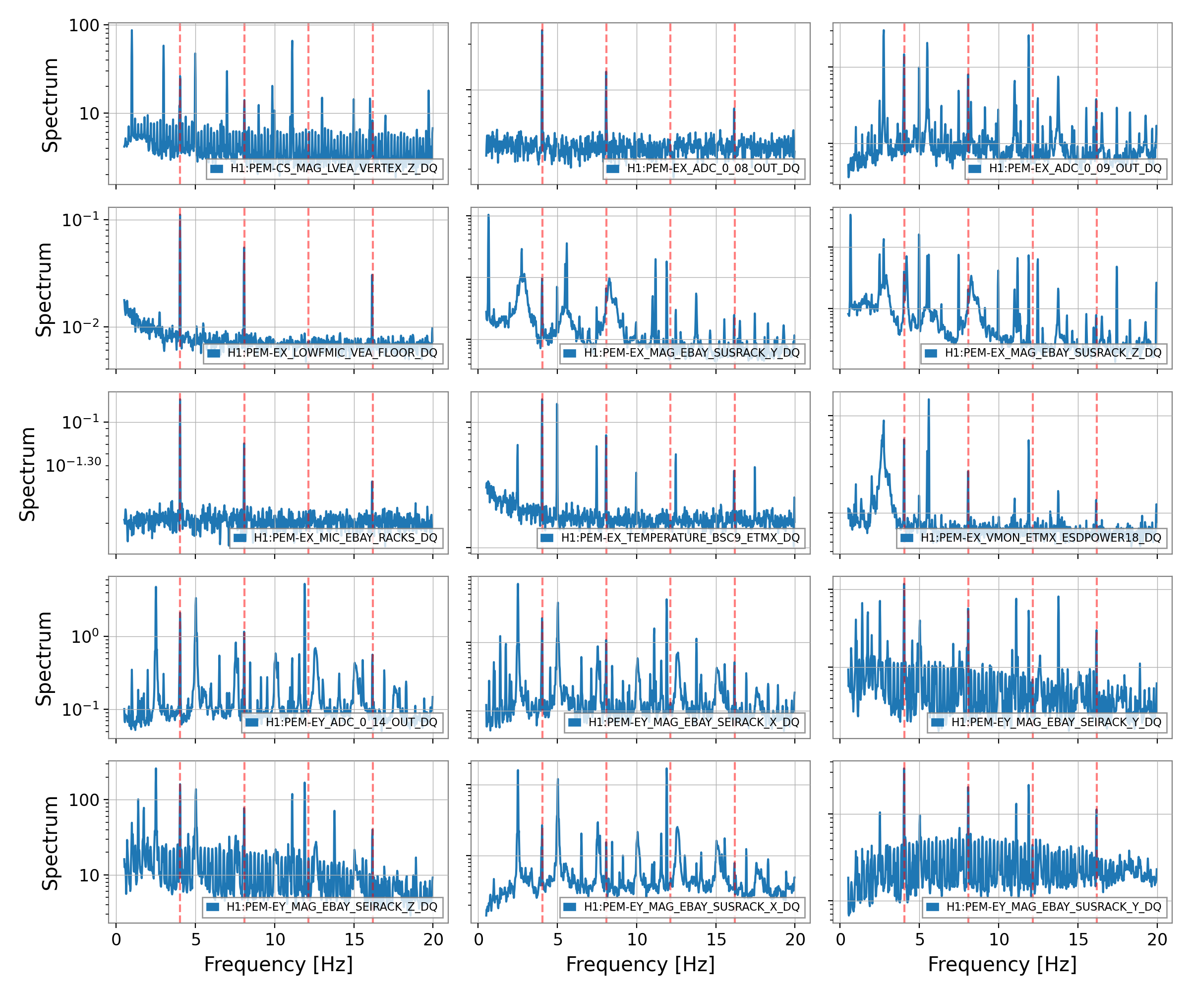
Unfotunately turning off the cosmic ray power supply did not remove the intermittent 4.05 Hz bumps in DARM, even though all the CS signals that showed a large peak at 4.06 Hz are now clean.
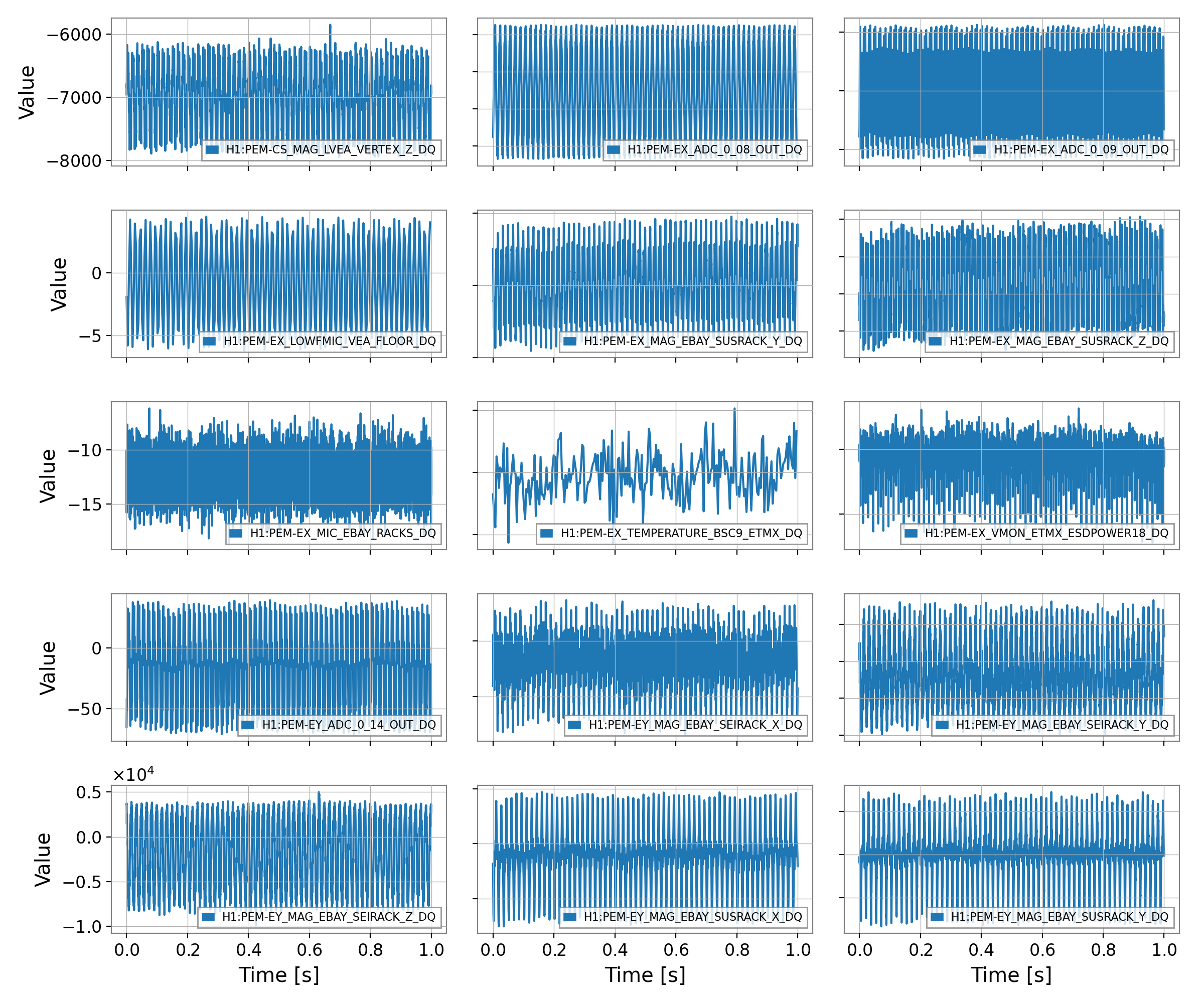
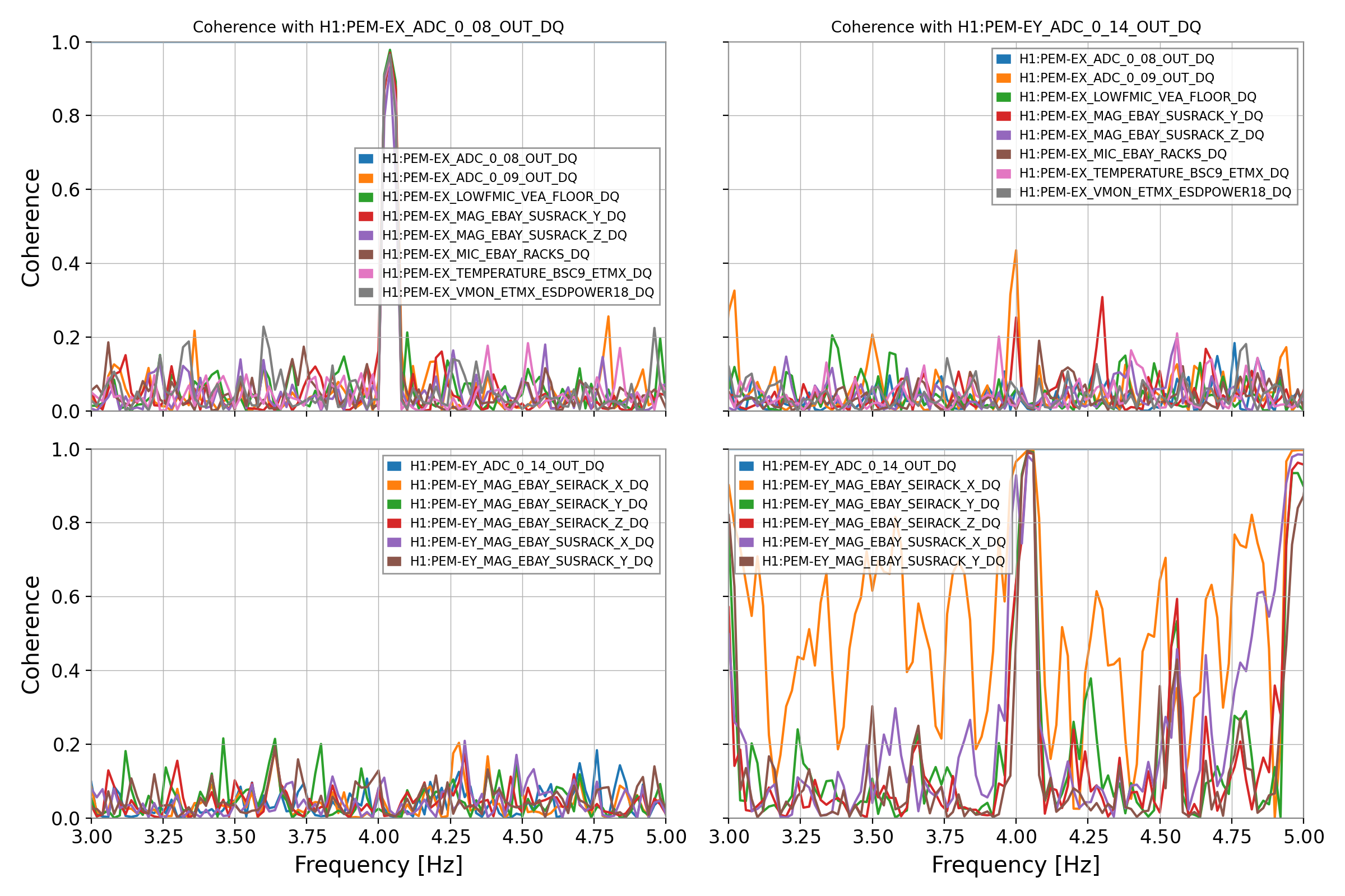
Looking again at all the signals that contain a peak around 4.05 Hz, we now have
          H1:PEM-CS_MAG_LVEA_VERTEX_Z_DQ 4.050 Hz
               H1:PEM-EX_ADC_0_08_OUT_DQ 4.040 Hz
               H1:PEM-EX_ADC_0_09_OUT_DQ 4.040 Hz
          H1:PEM-EX_LOWFMIC_VEA_FLOOR_DQ 4.040 Hz
         H1:PEM-EX_MAG_EBAY_SUSRACK_Y_DQ 4.040 Hz
         H1:PEM-EX_MAG_EBAY_SUSRACK_Z_DQ 4.040 Hz
             H1:PEM-EX_MIC_EBAY_RACKS_DQ 4.040 Hz
      H1:PEM-EX_TEMPERATURE_BSC9_ETMX_DQ 4.040 Hz
       H1:PEM-EX_VMON_ETMX_ESDPOWER18_DQ 4.040 Hz
               H1:PEM-EY_ADC_0_14_OUT_DQ 4.040 Hz
         H1:PEM-EY_MAG_EBAY_SEIRACK_X_DQ 4.040 Hz
         H1:PEM-EY_MAG_EBAY_SEIRACK_Y_DQ 4.040 Hz
         H1:PEM-EY_MAG_EBAY_SEIRACK_Z_DQ 4.040 Hz
         H1:PEM-EY_MAG_EBAY_SUSRACK_X_DQ 4.040 Hz
         H1:PEM-EY_MAG_EBAY_SUSRACK_Y_DQ 4.040 Hz
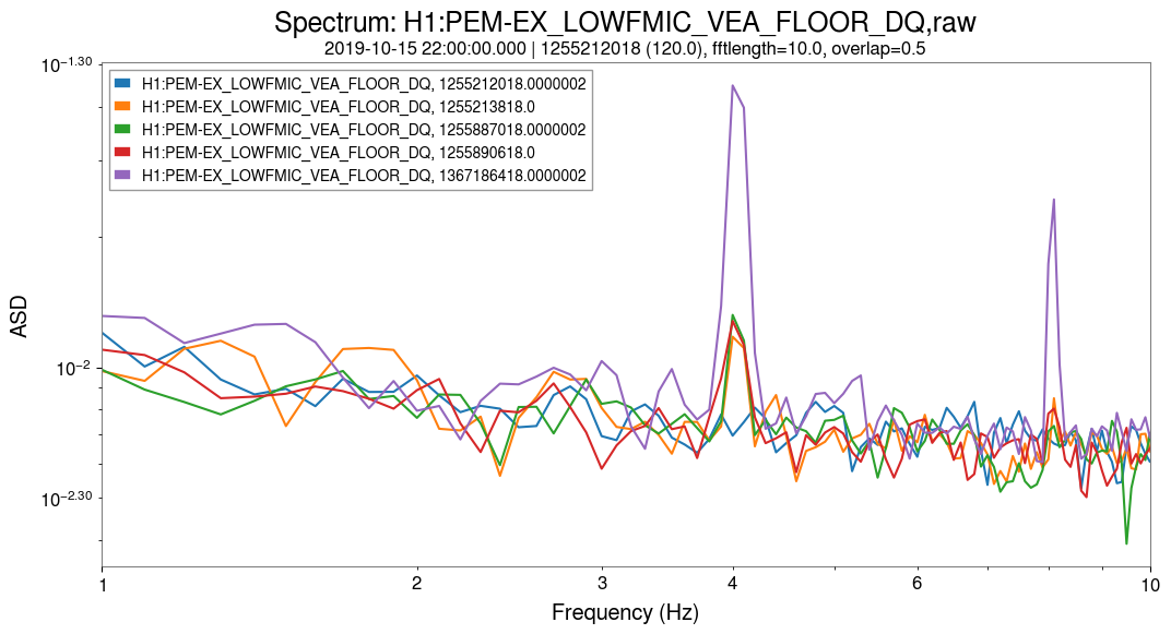
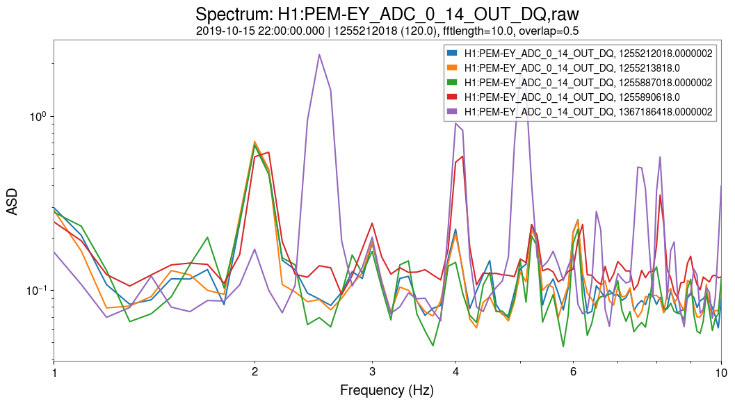
Attached plots shows spectra and time series. Although the frequency of all peaks is very close, EX signals are only coherent among themselves, and not with EY signals, and the other way around too. So it looks like at both end stations there is a source of 4.04 Hz that is local. Maybe a clue? Still, we don't have evidence that those sources are related to the DARM noise.
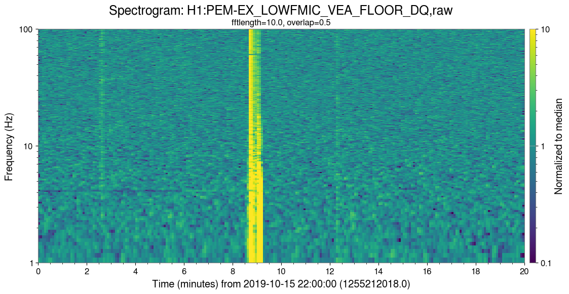
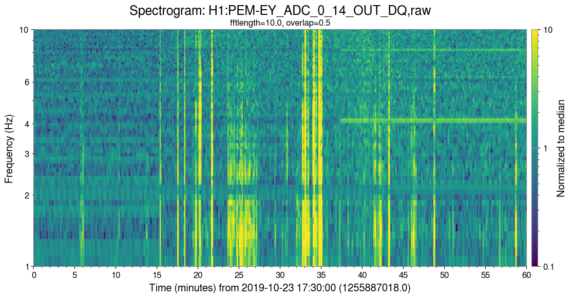
To help track down the source of these lines, I've been investigating the time this feature appeared in these channels. The two channels that were the first to have this feature are H1:PEM-EX_LOWFMIC_VEA_FLOOR_DQ and H1:PEM-EY_ADC_0_14_OUT_DQ, which both have had a 4 Hz line present since October 2019. The exact time of appearance for each is:
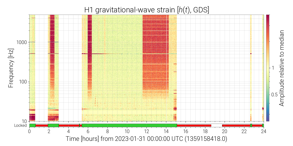
The attached spectrograms show the lines appearing at the above times. I have also includes plots of the channel spectra (plot 3 and plot 4) that show the 4 Hz line before/after these times, as well as a recent time (2023-05-03 22:00:00).
Looking through the alogs posted on these days, there may be an association to install work for BRS heaters. The related EX work (alog 52494) was on 2019-10-15, and the EY work (alog 52542) was on 2019-10-23. The time on both days roughly lines up with when the lines appeared.
The full day shift reports for these days are alogs 52495 and 52656. SInce these days were during the O3a-O3b commissioning break, there are a number of other activities that could be related.
I checked several spectragras from the summary pages during the last month of O3. There was no sign of the 4 Hz bumps.
Looking back at spectrograms since the restart, the first evidence I could find of the 4 Hz bumps is on January 31, 2023. I could not find any sign of the 4 Hz bumps in any lock stretch before that time
Under Robert's suggestion that this might have resulted from some alignment change of the beam at EX (LHO:69578), the ISC_LOCK guardian archives show the following A2L gain changes in January 2023:
The issue with trying to blame the 13 Jan gain change is that there were subsequent long locks with high sensitivity around 30 Hz that did not show the bumps.
Since January, there was also a retuning of the IY P2L/Y2L (commit 463245ed, see LHO:69082).
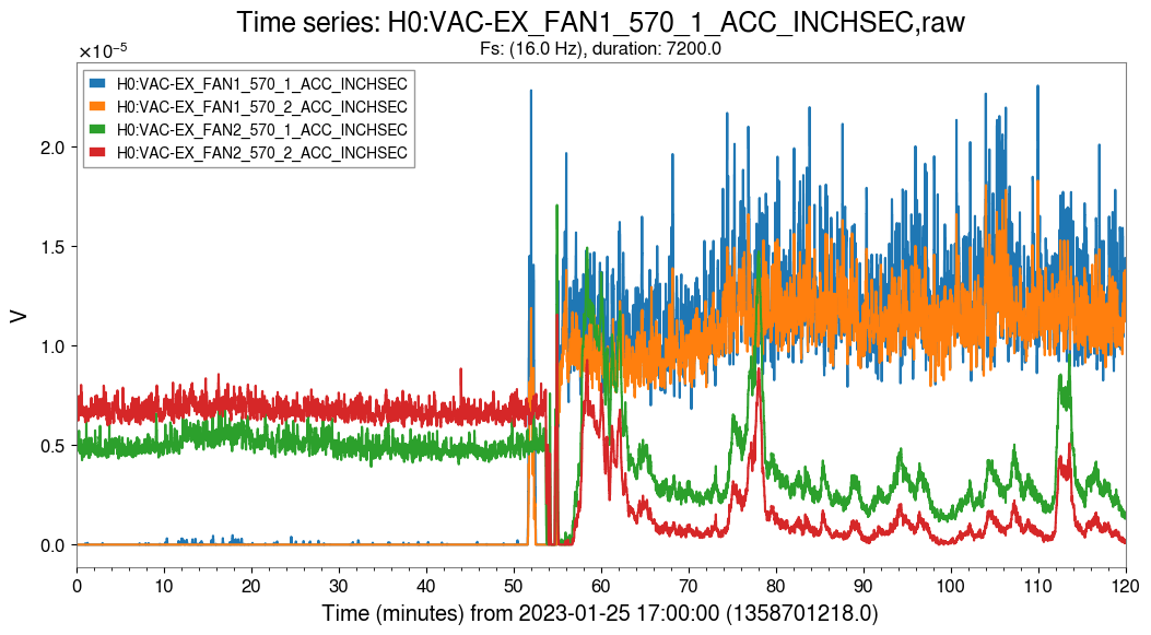
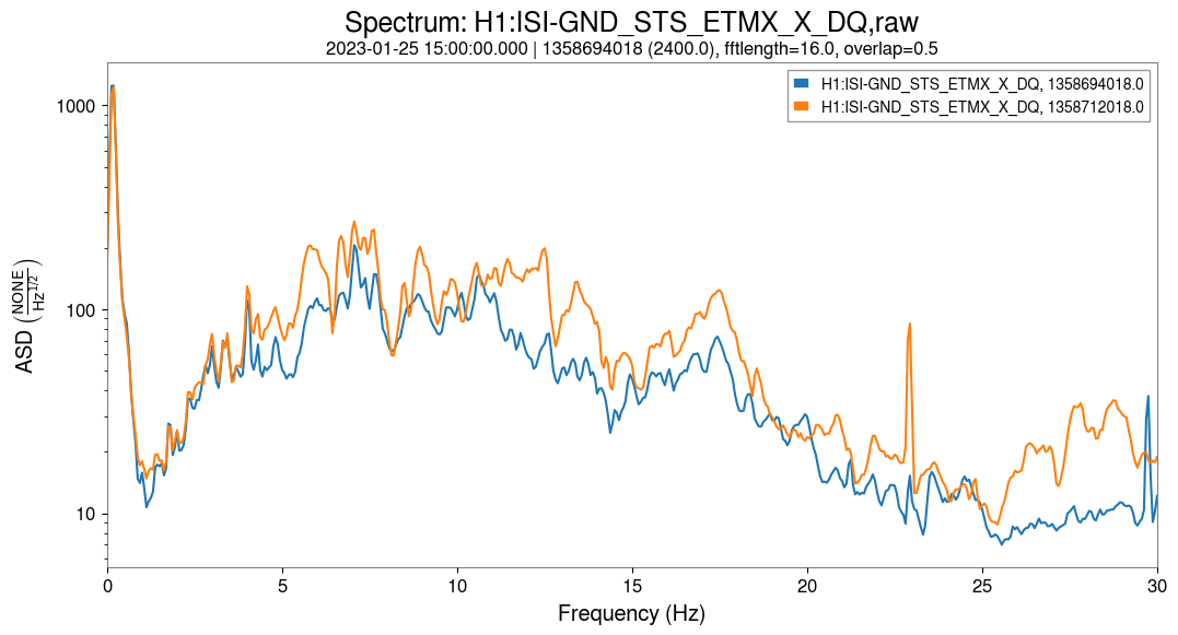
Some more clues — seems like the ground motion at EX from 3 Hz to 30 Hz experienced a step increase on January 25 and has not settled back down since then. The Güralps and STSs agree on this point, but as for what the ground motion was like in the fall of 2022 they seem to diverge.
Looking at the summary pages in fall of 2022 it seems like the bumps were intermittently present in DARM, e.g.: https://ldas-jobs.ligo-wa.caltech.edu/~detchar/summary/day/20220902/#gallery-6
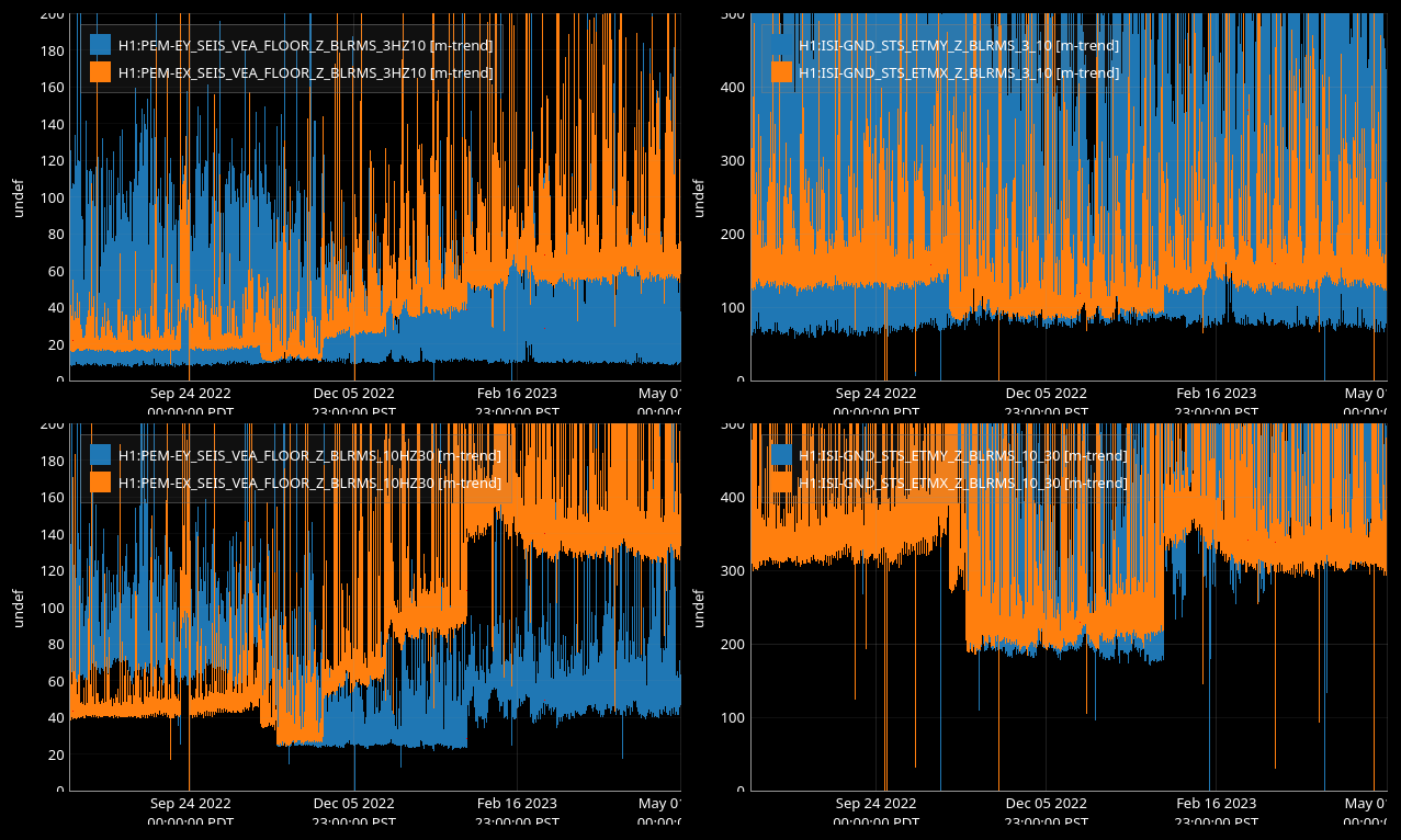
The increase in ground motion corresponds to turning on FAN1 at each of the end stations. Betsy points to alog 67055 indicating this work, and the change can be seen on the fan vibrometers (first attached plot). There is a peak at 22.5 Hz that pops up, and a broad increase in noise which includes the 4 Hz region, though not so strongly (attachment 2).