J. Betzwieser, L. Dartez, E. Goetz, J. Kissel

We've circled the wagons to try to understand why we're consistently getting things wrong when we try to update the "reference model DARM Loop transfer function values at calibration frequencies" (aka what the calibration group typically refers to as simply "EPICs Records") and get time-dependent correction factors (TDCFs) to the IFO's sensing and actuation functions that are *very* inconsistent with MCMC fit values for corresponding parameters (overall gain of the sensing function [often loosely referred to as the "optical gain"], coupled cavity pole frequency, and the actuation strengths for each of the three ETMX actuator stages). Namely, yesterday's attempt by Louis, LHO:68856 convinced us that we've fundamentally forgotten about *something* between O3 and O4, and it's manifested in how the latest version of pyDARM is written.

While we can't say that we've solved *all* of the issues, we have found and remembered the *a* major thing, and it has to do with the differences between how GDS calculates TDCFs and CAL-CS calculates TDCFs, and our valiant efforts to change the infrastructure for for O4, such that both are doing the same thing.

Here's the fundamentals of the TDCFs:
    (A) In order to determine things like the (relative) optical gain, cavity pole, we always need to find the transfer function between of DARM_ERR and PCAL, i.e. DARM_ERR / PCAL.

    (B) Both GDS and CAL-CS use demodulation techniques to find this transfer function, taking some version of the in-loop signals, DARM_ERR|_OMC and PCAL|_END, band-passing them, and beating them against a "local" oscillator to find I and Q, or real, and imaginary components of those demodulated signals, and then taking the coherent, complex ratio of the two sets to form the transfer function.

    (C) Both pipeline use the same reference model transfer function values (EPICs records) to divide out known stuff about the electronics, suspension dynamics, etc.

    (D) Both pipelins use the CAL-CS copy of the in-loop DARM_ERR signal, DARM_ERR|_CS. This signal is delayed by one 16 kHz clock cycle, exp(-1i*phi) as its shipped over inter-process communication from the OMC model to the CAL-CS model,
        DARM_ERR|_CS  = DARM_ERR|_OMC * exp(-1i*phi)        (1)
           or
        DARM_ERR|_OMC = DARM_ERR|_CS  * exp(+1i*phi)        (2)

    (E) There's been a constant point of confusion (discrepancy, or loss of institutional memory) that CAL-CS reads PCAL from corner station, PCAL|_CS, where GDS reads PCAL from the end-station, PCAL|_END,
        PCAL|_CS  = PCAL|_END * exp(-1i*phi)                (3)
           or
        PCAL|_END = PCAL|_CS * exp(+1i*phi)                 (4)

    and reconciling that between the two pipelines. In the O2-O3 era, we *thought* we reconciled the discrepancy by modifying the CAL-CS pipeline's PCAL demod phase, adding a negative phase that corresponded to the value (phase) of a one 16 kHz clock cycle delay at each calibration line frequency,
        phase = 180/pi*angle(exp(-1i*2*pi*linefreq*(1/16384 Hz)))
      You can see this adjustment every time we've had to mode a PCAL calibration line frequency, and enter in a new phase value LHO:48534, LHO:44005, LHO:31748, etc.

    (F) In April 19 2019, when we got bit one last time by this loss of institutional memory, and we vowed to "fix all this" and demand that "every part of both the GDS and CAL-CS pipeline should ingest the same thing, and compute the same thing, and use the same EPICs records" -- see IIET Ticket 12638, pydarm issue #17.

    (G) Between the end of O3 and now (yes, for 3 years), Evan's been championing a new version of pyDARM, and among many other improvements, we'd that hoped to resolve the issues with the computation of the EPICs records. In the last couple of attempts to "push" those EPICs records (LHO:68856), as well as attempts to move TDCF calibration line frequencies LHO:66268, the resulting TDCFs were wildly different from the MCMC fit values that we expect -- most typically in the optical gain, kappa_C, and the coupled cavity pole frequency, f_cc.

    (H) In July 2022 (LHO:64005), I added a channel to the frames, H1:CAL-DELTAL_REF_PCAL_DQ, which is a corner station copy of which ever PCAL we're using as our reference, i.e. PCAL|_CS -- such that the GDS pipeline *could* switch over to using the this version of the PCAL.

Now you're caught up with yesterday, when Louis and I sent out the bat signal to circle the wagons.

After comparing old EPICs records (not updated since O3) against new EPICs records (recently computed by modern pyDARM and a modern pyDARM model parameter set),
CLUE 1: Joe found that the *newly* computed reference model transfer function value for the so-called "PCAL Corrections" for the 410.3 showed a difference, only in phase, of 18.03 deg against the old values. It smelled suspiciously like double the phase delay expected to be put in the DEMOD PHASE, 9.02 deg,
    180/pi*angle(exp(-1i*2*pi*410.3*(1/16384))) = -9.0154,
    180/pi*angle(exp(-1i*2*pi*410.3*(2/16384))) = -18.031
Suspicious that we were double counting this delay, we went back to the O3 code that computed the PCAL corrections.

Remember, PCAL corrections are the offline corrections one needs to perform on any copy of any PCAL RX or TX PD channel in true DARM displacement caused by PCAL, DELTAL_PCAL, which includes the stuff that the front-end doesn't do to the channel before storage,
    * arm sign                  # a conversion of pcal force (which is in the minus
                                # longitudinal direction, in test mass suspension
                                # euler basis) to DARM force (PCALY makes negative
                                # DARM, PCALX makes positive DARM)

    * 1/f^2                            # the "rest" of the TST-stage force to TST-stage
                                       # displacement transfer function, which *acts*
                                       # like a "dewhitening" filter

    * 1 / (analog AA)                         # high frequency inversion of the response
                                              # of the 65 kHz analog AA filter for any
                                              # readback signal

    * 1 / (digital 65 kHz to 16 kHz delay)    # high frequency inversion of the response
                                              # of the 65 kHz to 16 kHz downsampling filter
But also, critically, where the copy of the pcal signal is used -- the corner station or end-station -- the pcal correction must also either include or exclude the exp(-1i*phi) clock cycle delay, as defined above in Eqs. (3) and (4).

The new pydarm code (as of git hash 20668eb4), has a method that produces this correction, compute_pcal_correction. Importantly, in that version, it has a boolean flag, where the user of the method can determine whether the user is correcting a PCAL|_CS or a PCAL|_END channel. When "endstation=False," then it's to be used for a cornerstation copy of the PCAL, PCAL|_CS, and it divides by one 16 kHz clock-cycle delay, which would create the equivalent of equation (4) from above,

    (pcal_sign *
     pcal_dewhitening /
    (pcal_analog_aa_hi_f * pcal_digital_aa) /
     end_to_calcs_response)

where end_to_calcs_response is either a transfer function of 1 (when endstation=True), or a one 16 kHz clock-cycle delay (when endstation=False).

Stumped, because this makes sense to us, we went to old O3 codesensing.py, line 215,

    pcalCorrection = signal.freqresp(pcaldewhitening, 2.0*np.pi*freq)[1] /              # 1/f^2
                     ( signal.freqresp(AAanalog, 2.0*np.pi*freq)[1] *                   # 1/(analog AA)
                     AAanalog_delay/abs(signal.freqresp(AAanalog, 2.0*np.pi*0.01)[1])   # (Some crap to fix a bad model of the analog AA)
                     * totalSensingDigital_freqresp                                     # 1/(digital AA)
                     * omcDelay_freqresp )                                              # A poorly named variable that resolves to a TF of 1

CLUE #2: we find that O3's pcal correction did not contain any advance or delay. We collectively recall: this variable was designed to be the correction to PCAL|_END channels, and did not consider the possibility of a corner station PCAL|_CS channels.

So "how did it all ever even work??" that drove us to the O3 code that made the EPICs record itself, which *used* pcalCorrection, in , lines 431 - 434

    EP9 = pars.Cpars.pcal.Pcal2DARMactSign *                   # arm sign
          sensProd.pcalCorrection[4] *                         # (1/f^2)*(1/analog AA)*(1/digital AA)
          np.exp(-2.0 * np.pi * 1j * freq[4] * 1/16384.0)      # exp(-1i*phi)

which reveals ... there's a delay in here! But ... GDS computes its TDCFs from PCAL|_END channels, so it doesn't need Eqs. (3) and (4) and shouldn't need any delay. And yet, both CAL-CS and GDS use this same EPICs record to compute TDCFs... CLUE #3: OH YEAH Eqs. (1) and (2) -- this so-called "PCAL_CORRECTION" EP9 (and their equivalent EPs at other frequencies) isn't actually *just* correcting PCAL, it's a correction to the DARM_ERR|_CS / PCAL|_END transfer function, because GDS reads in DARM|_CS, not DARM|_OMC, and thus needs Eq. (2).

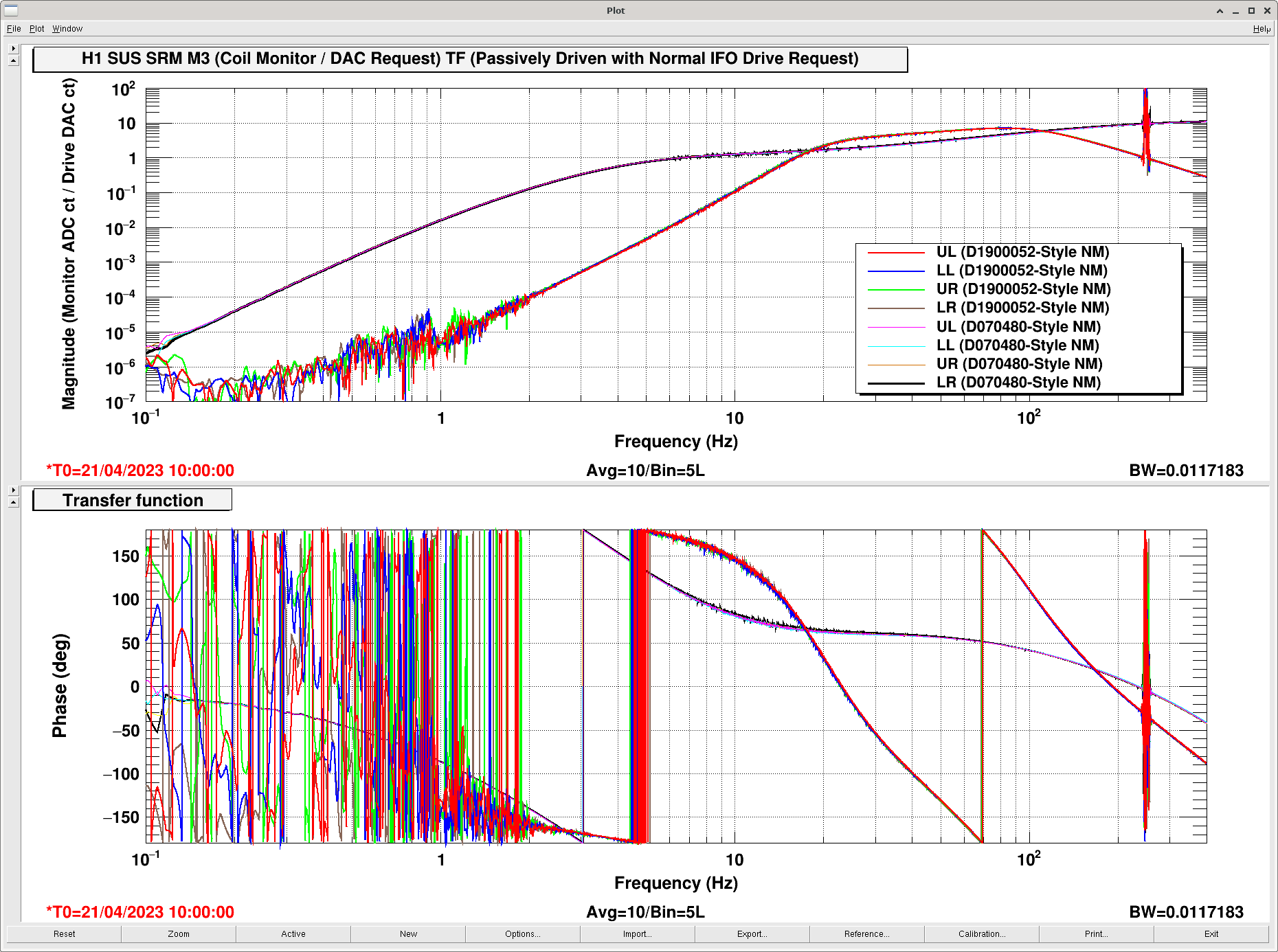
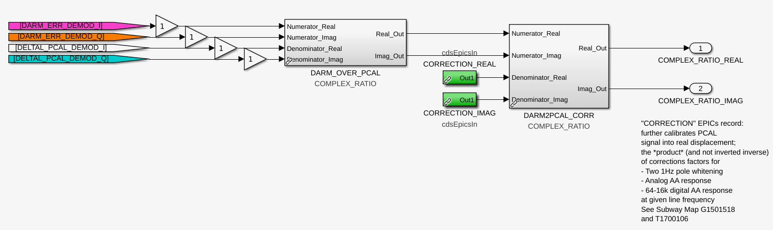
This drove us to remind ourselves how these EPICs records are actually applied in the front-end code. the first attachment shows that it gets even nastier because CLUE #4: the "PCAL corrections" EP9 (and the like), are *divided* into the DARM|_CS / PCAL|_CS transfer function.

If you're not pulling our hair out already by this point, don't worry, Joe, Evan, Louis, and I have *definitely* pulled out enough hair today already for you.

This means that this is the math that's happening in the GDS algorithm,

    DARM_ERR|_CS      1        DARM_ERR|_CS                                     1
    ------------  *  ---   =   ------------  * --------------------------------------------------------------------
     PCAL|_END       EP9         PCAL|_END     (arm sign) * (1/f^2) * (1/analog AA) * (1/digital AA) * exp(-1i*phi)

                               DARM_ERR|_CS                         exp(+1i*phi)
                           =   ------------  * -----------------------------------------------------
                                 PCAL|_END     (arm sign) * (1/f^2) * (1/analog AA) * (1/digital AA)

                                                DARM_ERR|_CS * exp(+1i*phi)
                           =   -----------------------------------------------------------------
                                 PCAL|_END * (arm sign) * (1/f^2) * (1/analog AA) * (1/digital AA)

                               DARM_ERR|_OMC
                           =  ---------------
                               DELTAL_PCAL

And in order for the CAL-CS pipeline to use the same EPICs record and produce the same answer -- but with the PCAL|_CS -- CAL CS has to install a "fudge" by altering the phase of the PCAL DEMOD, i.e. in the denominator channel before the transfer function is taken, CLUE #5: but that DEMOD phase has the opposite sign than you expect:

    DARM_ERR|_CS             1              1        DARM_ERR|_CS                                             1
    ------------ * -------------------- *  ---   =   ------------  * ------------------------------------------------------------------------------------------
     PCAL|_CS      (DEMOD exp(-1i*phi))    EP9         PCAL|_CS     (arm sign) * (1/f^2) * (1/analog AA) * (1/digital AA) * exp(-1i*phi) * (DEMOD exp(-1i*phi))

                                                     DARM_ERR|_CS * exp(+1i*phi)                              1
                                                 =   -----------------------------   * -----------------------------------------------------
                                                     PCAL|_CS  (DEMOD exp(-1i*phi))   (arm sign) * (1/f^2) * (1/analog AA) * (1/digital AA)

                                     THE DENOMINATOR ONLY BECOMES PCAL|_END IF (DEMOD exp(-1i*phi)) == exp(+1i*phi)

                                                                            DARM_ERR|_OMC
                                                 =   -----------------------------------------------------------------
                                                     PCAL|_END * (arm sign) * (1/f^2) * (1/analog AA) * (1/digital AA)

                                                    DARM_ERR|_OMC
                                                 =  -------------
                                                     DELTAL_PCAL

So in in the most convoluted way, with delays turning into advances by a series of confusing divisions across disparate code, front-end models, and hacks on hacks, and a confusing convention with the front end's DEMOD phase system, somehow it all ended up working in O3.
Also notice, that if one computes the transfer function with both channels in the CAL-CS model, then both experience a one 16 kHz clock cycle delay, and the delays, or advances cancel, and it's like you're reading in the channels from their original location,

    DARM_ERR|_CS      DARM_ERR|_CS    exp(+1i*phi)     DARM_ERR|_OMC
    ------------   =  ------------ *  -----------   =  -------------
      PCAL|_CS          PCAL|_CS      exp(+1i*phi)        PCAL|_END

This fact was exploited a few times early on when folks first were debating who should have what delay when and how, and we ended up confusing ourselves by not including explicitly including advances or delays at all.

So, let's now zoom forward back again to O4, where we've got new code from Evan, where he's pre-included the option to envoke computer_pcal_correction with either the endstation set to True (no delay/advance) or False (dividing by a delay exp(-1i*phi), or equivalently multiplying by an advance exp(+1i*phi)).

How is the EPICs record computed? Now we head to the compute_epics_records in the calcs.py module (last changed at git hash version 60d261c4), to find CLUE #6: there's an error in this code, in that it does not apply the extra exp(-1i*phi) delay here:
        PCAL_LINE2_CORRECTION = pcal_correction[4]          # used to be EP9 from above

and for brevity we'll call this version "CORR".

On top of *this* CLUE #7: Louis and I removed the CAL-CS fudge delay yesterday, thinking "Oh, well, every pipeline is computing the DARM / PCAL transfer function ratio with the 'fixed' EPICs records with endstation set to False, so we shouldn't need the DEMOD phase fudge.

That means the CAL-CS pipeline as of yesterday instead has been computing

    DARM_ERR|_CS          1           1        DARM_ERR|_CS                            (DEMOD exp(0))
    ------------ * ------------- *  ----   =   ------------  * --------------------------------------------------------------------
      PCAL|_CS     (DEMOD exp(0))   CORR         PCAL|_CS      (arm sign) * (1/f^2) * (1/analog AA) * (1/digital AA) * exp(+1i*phi)

                                               DARM_ERR|_CS * (DEMOD exp(0))                               1
                                           =   -----------------------------    * -----------------------------------------------------
                                                  PCAL|_CS * exp(+1i*phi)         (arm sign) * (1/f^2) * (1/analog AA) * (1/digital AA)

                                             DARM_ERR|_CS                              1
                                         =   ------------ * ---------------------------------------------------
                                               PCAL|_END    (arm sign) * (1/f^2) * (1/analog AA) * (1/digital AA)

                                             DARM_ERR|_CS
                                         =   ------------
                                             DELTAL_PCAL

                                              DARM_ERR|_OMC
                           (DOES NOT EQUAL)  ---------------
                                               DELTAL_PCAL

Where one can see that, when one sets endstation to False, and you don't include any fudge phase in the PCAL DEMOD, there's a now missing advance that propagates the CAL-CS copy of DARM_ERR|_CS back to DARM_ERR|_OMC, and this messes up all computation of TDCFs that involve PCAL, which y'know is ALL of them. We see it manifest the most on the 410.3 Hz line, and thus in the calculation of the (relative) optical gain kappa_C and coupled cavity pole frequency, 180/pi*angle(exp(-1i*2*pi*(410.3 Hz/16384 Hz)) = -9.015 is MUCH larger than the 17.1 Hz line's phase modifier of 180/pi*angle(exp(-1i*2*pi*(17.1 Hz/16384 Hz)) = -0.3757.

This also explains why, when we compare EP9 with one delay, against CORR with one advance, we see a 2x abs(9.015) = 18.031 deg change.

By this point, Evan, Joe, Louis, and I all agree -- because the transfer function (DARM_ERR|_CS / PCAL|_CS) * (1/CORR) is missing an advance to propagate DARM_ERR from CAL-CS back to the OMC, or DARM_ERR|_CS * exp(+1i*phi) = DARM_ERR|_OMC, Eq. (2) from above, we can either
    (i) Fudge the phase of DARM_ERR DEMOD with +9.015, to create the missing advance, or
    (ii) Continue with the hot mess of convolution and fudge the phase of the PCAL DEMOD with -9.015

and in the mean time, Evan will edit O4-era pyDARM to include a darm_advance in the computation of CORR, and rename the EPICS record variable to be something like DARM_OVER_PCAL_CORR or something.

%%%%%%%%%%%%%%%%%%%%%%%%%%%%%%%

OK, all of the above was all the whiteboard math and history, but as we all know -- you can math 'til your blue in the face, but when it comes to minus signs, multipications vs. divisions, or delays vs. advances -- you've got a 50/50 shot, and the interferometer will tell you very quickly if you've got it right.

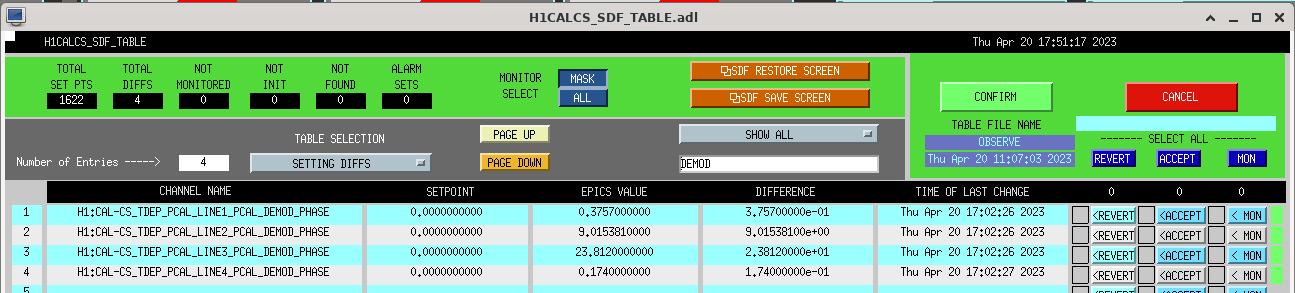
So, as a quick test, Louis and I went with option (ii), ignored CLUE #5 'cause "who would believe that??," and installed the "appropriate" DEMOD phase fudges, exp(-1i*phi), in all the PCAL line DEMOD phases.

    PCAL line
    Frequency (Hz)    Demod Phase Channel                           Phase (deg)
    7.93              H1:CAL-CS_TDEP_PCAL_LINE4_PCAL_DEMOD_PHASE    -0.174
    17.1              H1:CAL-CS_TDEP_PCAL_LINE1_PCAL_DEMOD_PHASE    -0.3757
    401.3             H1:CAL-CS_TDEP_PCAL_LINE2_PCAL_DEMOD_PHASE    -9.01538
    1083.7            H1:CAL-CS_TDEP_PCAL_LINE3_PCAL_DEMOD_PHASE    -23.812

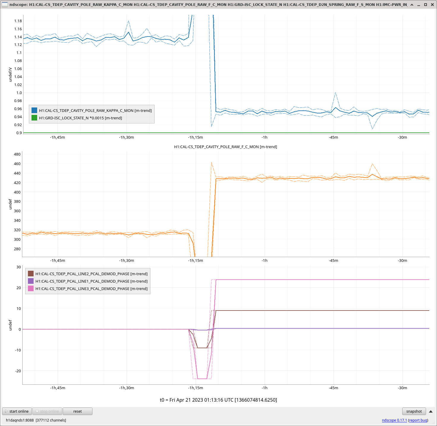
THE IFO LAUGHED AT US, SAYING "HA! YOU FORGOT ABOUT CLUE #5!"

See Second attachment.
With a brief moment in time that we installed these negative phase rotations, the already nonsensical ~310 Hz coupled cavity pole frequency and 1.12 relative optical gain shot to ...let's just say "off the map bad.
So, we installed positive phase fudges...

    Frequency (Hz)    Demod Phase Channel                           Phase (deg)
    7.93              H1:CAL-CS_TDEP_PCAL_LINE4_PCAL_DEMOD_PHASE    +0.174
    17.1              H1:CAL-CS_TDEP_PCAL_LINE1_PCAL_DEMOD_PHASE    +0.3757
    401.3             H1:CAL-CS_TDEP_PCAL_LINE2_PCAL_DEMOD_PHASE    +9.01538
    1083.7            H1:CAL-CS_TDEP_PCAL_LINE3_PCAL_DEMOD_PHASE    +23.812

and the cavity pole frequency and optical gain settled on a MUCH more reasonable 430 Hz, and (relative) optical gain of 0.95!

The cavity pole is consistent with the MCMC fits to the swept sine measurements and the change in optical gain is totally reasonable because we're *still* changing alignment and TCS settings.


WE FIGURED IT OUT, TEAM. WE DID IT.
We can trust the answers from front-end, CAL-CS computed TDCFs again...
and
There's something that doesn't make sense about the phase convention for the standard CDS DEMOD part, but we can figure that out later.