jeffrey.kissel@LIGO.ORG - posted 11:27, Tuesday 16 December 2025 (88546)
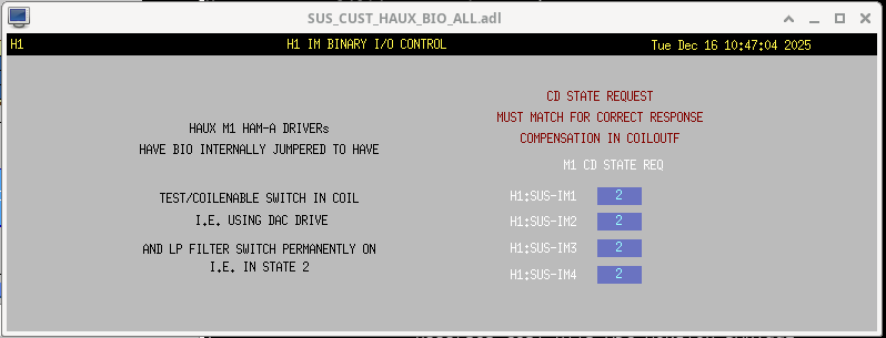
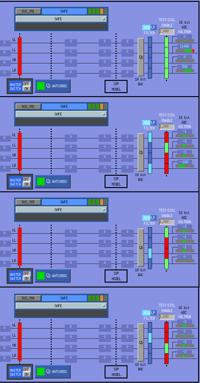
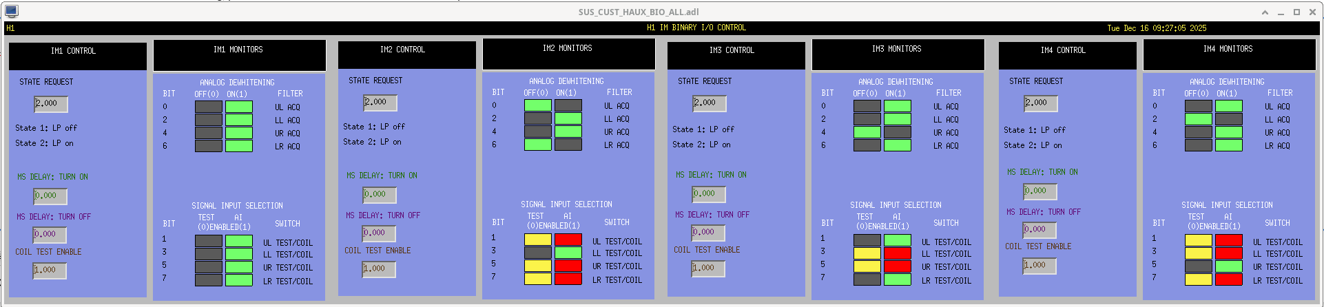
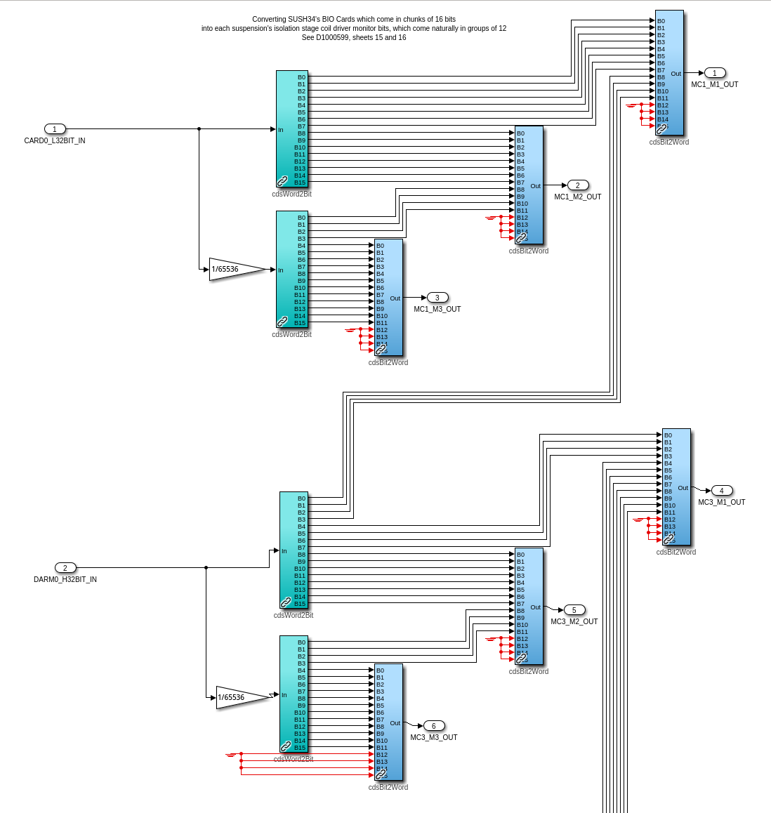
SUS IM1, IM2, IM3 and IM4 Online and Running post sush2a and sush2b merge to sush12
J. Kissel, O. Patane

After having sorted issues with the (non-existent) binary IO (see LHO:88542 and LHO:88544), and Oli has performed all the "usual" controls updates after a 32CH DAC upgrade, all of the HAUX suspensions -- IM1, IM2, IM3, IM4 -- are now confirmed functional, damped, and aligned.

We've left their guardians them in the ALIGNED state.

That means all SUS in HAM2 are fully functional on the new merged sush12 computer / IO chassis and following the drawing D0902810-v12. See analog changes in LHO:88519 and software changes in LHO:88527.