[RyanS, Jenne, all the other control room people, of whom there were many]
Summary: We can get to PREP_DC_READOUT_TRANSITION (at least once), but had trouble with OMC locking.
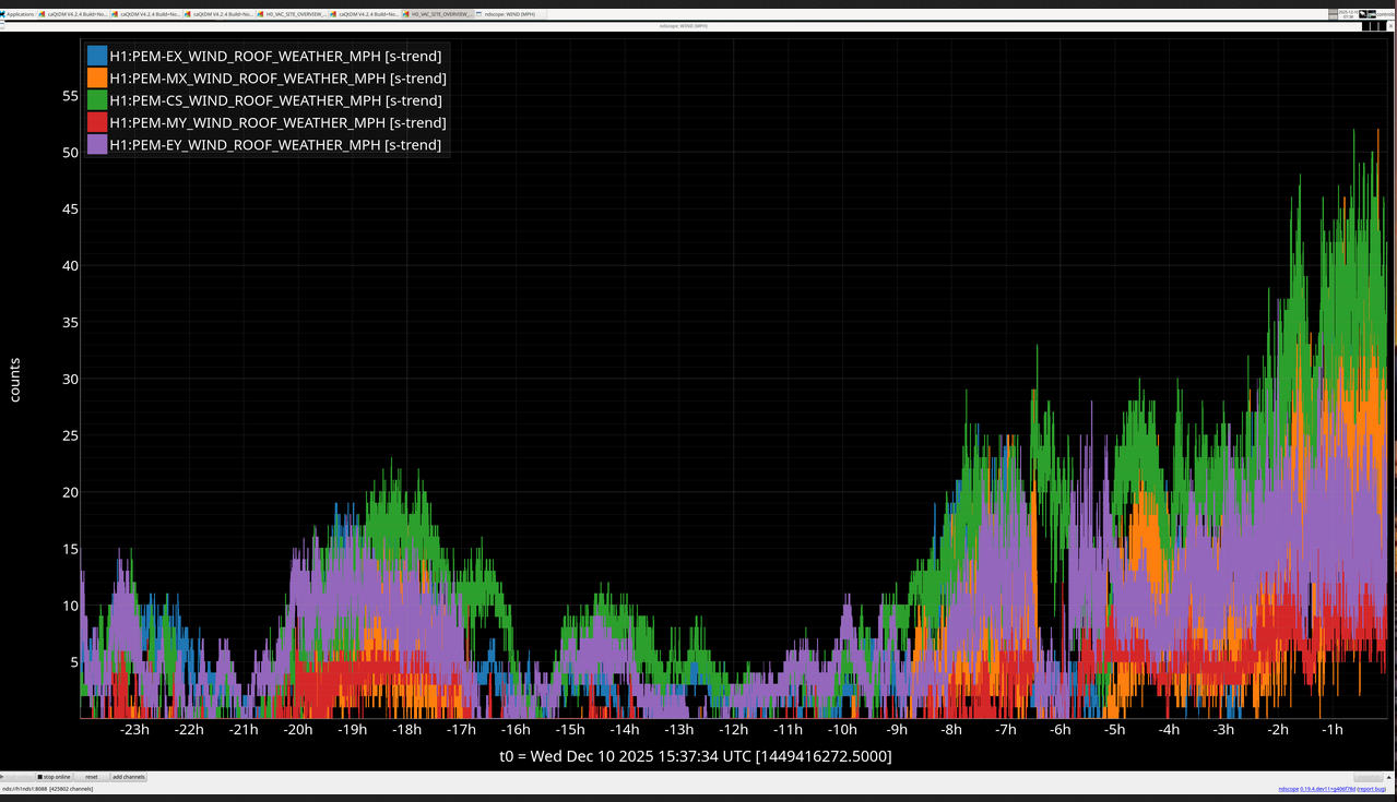
We tried some locking earlier in the day, first starting with doing the same trick as yesterday (alog 88432) and moving ITMX while ETM and TMS were controlled by green WFS to improve the COMM beatnote. However, I only ended up moving ITMX 0.3 urad in yaw. Because this was a small change and Sheila reminded me that we can lock (when the wind is low) with comm down at -10 dBm-ish, so I decided that next lock we'd just use the camera setpoints (which we did and was successful). During this time, we had to disable SRC1 and PRC1 in DRMI ASC because they were pulling the alignment away, and we weren't really on the POP QPDs at all. Anyhow, we got to PREP_ASC_FOR_FULL_IFO twice, but the alignment never looked excellent. We tried ENGAGE_ASC_FOR_FULL_IFO once, and it was really bad and killed the lock. The other time, we think that the seismic state changing from useism to windy caused us trouble (but, in retrospect, likely was only troublesome because the alignment was so poor).
We then realized that, after the big earthquakes from this weekend, our input pointing wasn't good. RyanS then set the IMs 1, 2, and 3 such that they matched their top mass osems (not necessarily their sliders). We then moved IM3 a little bit to get back to where we had been on IM4 Trans QPD before the power outage (pit of 0.239, yaw of -0.071). We were able to quite easily run through an initial alignment with this. During this and all subsequent initial alignments, we used the pre-power outage green setpoints (including cameras). The COMM beatnote was around -9 dBm, so that's pretty good.
Some time around here we had the -18 V failure, see alog 88446 for details.
Then, we did another initial alignment.
Then, the CDS team let us know that they needed to reboot all the models, see alog 88448 for details. After all the models were back, Ryan restarted the ALS_[X,Y]ARM guardians using "guardctrl restart NODE", so they would know how to start their AWGs in case SCAN_ALIGNMENT needs to be run.
We then restored sliders to just after one of our recent inital alignments, and Ryan then reset the IMs 1-3 to their top mass osems again, and again moved IM3 to get us back to the pre-power outage spot on IM4. ....And did yet another initial alignment.
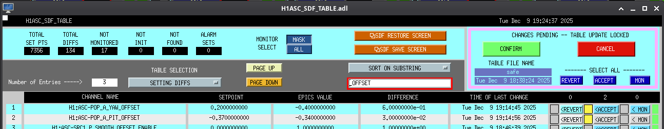
After this, we finally were able to try to lock for the first time in several hours! And things went really, really quite well. We basically didn't touch anything at all (PRC1 and SRC1 still disabled in DRMI ASC), and were able to lock to PREP_FOR_DC_READOUT! Yes, you read that right, ENGAGE_ASC_FOR_FULL_IFO did just fine on its own. The buildups went down then came back again, so we were a bit scared, but it kept hold of everything and was able to converge. The PRM's ADS alignment took a loooonng time to converge, which we've seen before after a power outage (eg, alog 86944), so after all of the ASC was on (including SOFT_LOOPS) and converged, I reset the POP_A offsets, and Ryan accepted them in safe.snap.
(Later, after some relocks, we're able to use PRC1 in DRMI ASC now that its offsets have been set. But, still SRC1 is left out since it's pulling things away).
The violin modes are quite high, but not so bad that it's impossible to get 2W locked.
We went to PREP_DC_READOUT_TRANSITION, and noticed that we were having trouble locking the OMC. We're still not sure what's going on here, and we're going to leave it for the night. We're hoping to leave it at PREP_DC_READOUT_TRANSITION, however the second time that we did ENGAGE_ASC_FOR_FULL_IFO, something pulled us away and we lost lock. We'll let it try one more time.
OMC locking troubles and symptoms:
- In TUNE_OFFSETS, the first time it tried to measure the transfer function, the magnitude would be way wonky (like, 40k rather than ~1), but it wouldn't go past there because the phase was more than 30 deg from 0 or 180. It would then try again to measure the TF.
- The second time, it would often get a sensible number, and the phase was fine. However, since ErrorFlag had been set to True the first time around and it never got set back to False on the next try, it would just fail again and cycle through DOWN. I added lines to set ErrorFlag to False if the phase measured okay.
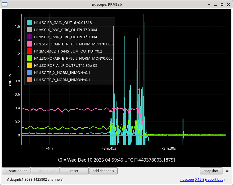
- We then started having troubles even getting it to lock on the carrier, although it looked like it found the carrier just fine, and had 16 mA on the DCPDs. It keeps saying "wrong mode?", even though the DCPDs were 16 mA.
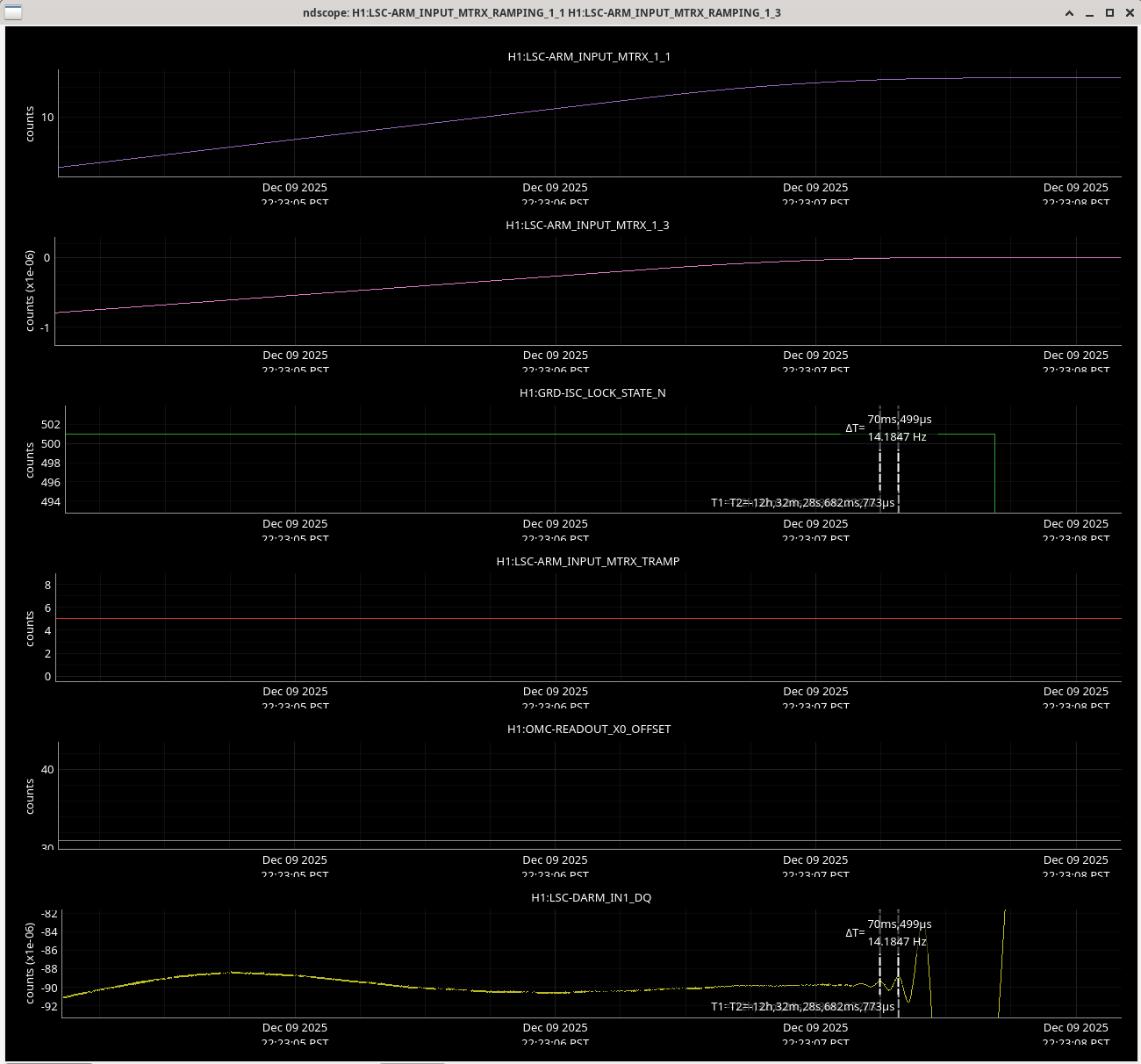
- One time, I found the carrier by hand and manual-ed over FIND_CARRIER. However, the TUNE_OFFSETS kept giving phases of ~145 deg (which is more than 30 deg away from 180, and thus a failure). I copied in the scale_offset value that the guardian calculated though, and then manual-ed over TUNE_OFFSETS. We lost lock when I tried to have ISC_LOCK take us to DC_READOUT, but in retrospect that's probably due to not having done the prep items in the main state of TUNE_OFFSETS that set up the OMC-READOUT path.


I'm running a temporary HWS-ETMX dummy IOC on cdsioc0 to "green up" the EDC.
cds_status_ioc was upgraded to expect +1 ADC in the site wide ADC count.