jeffrey.kissel@LIGO.ORG - posted 12:24, Tuesday 09 June 2026 - last comment - 12:27, Tuesday 09 June 2026(90546)
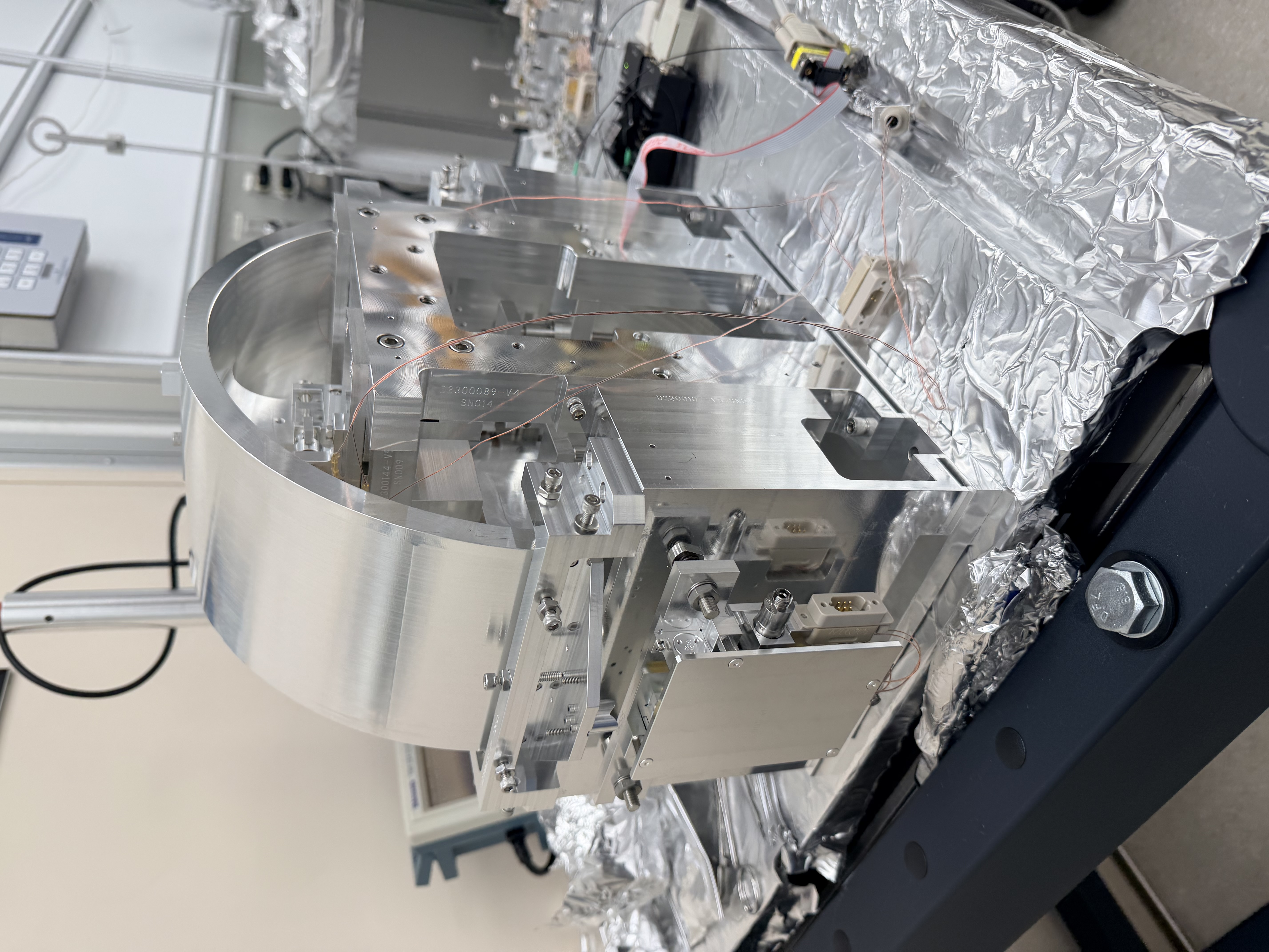
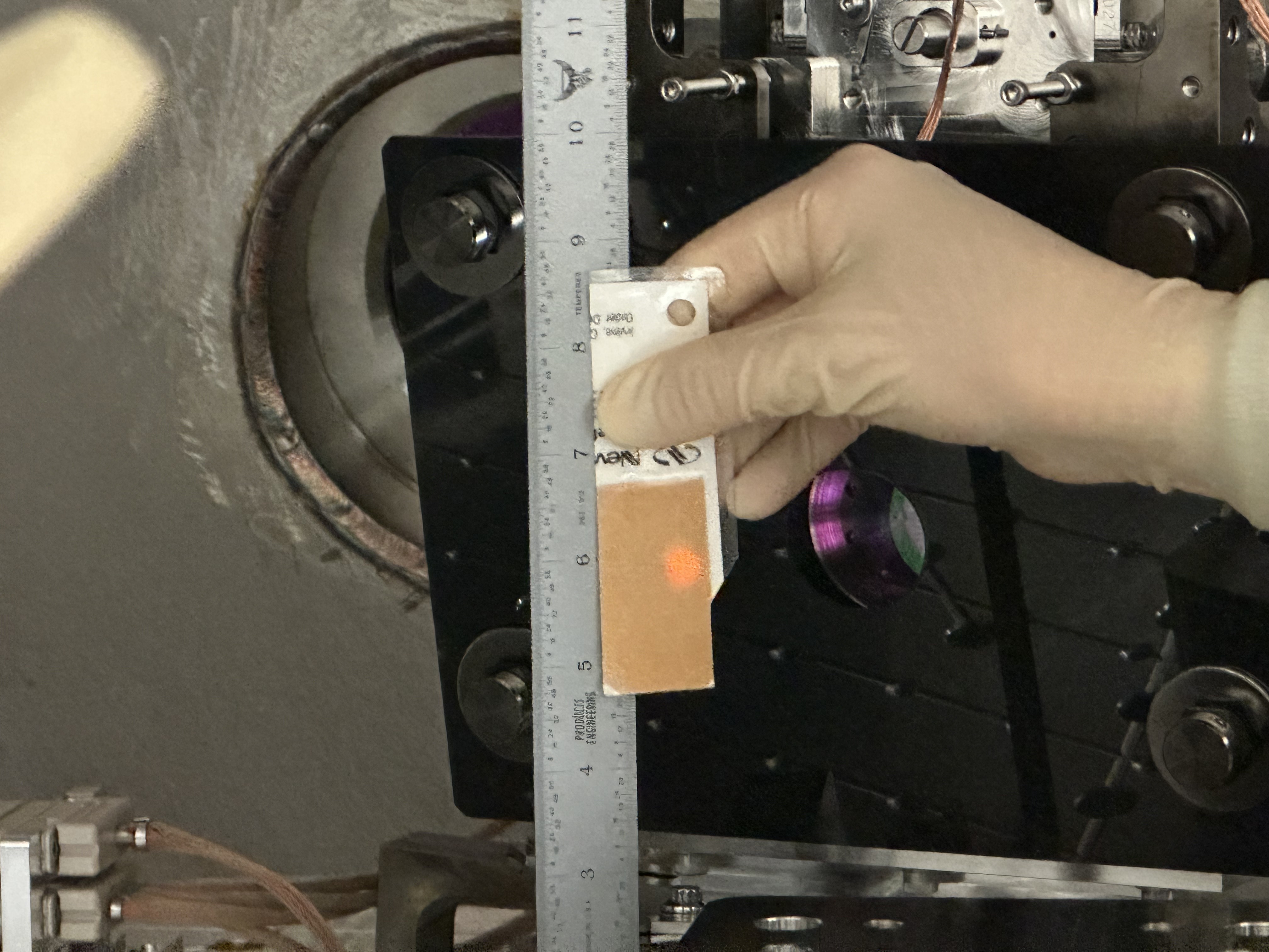
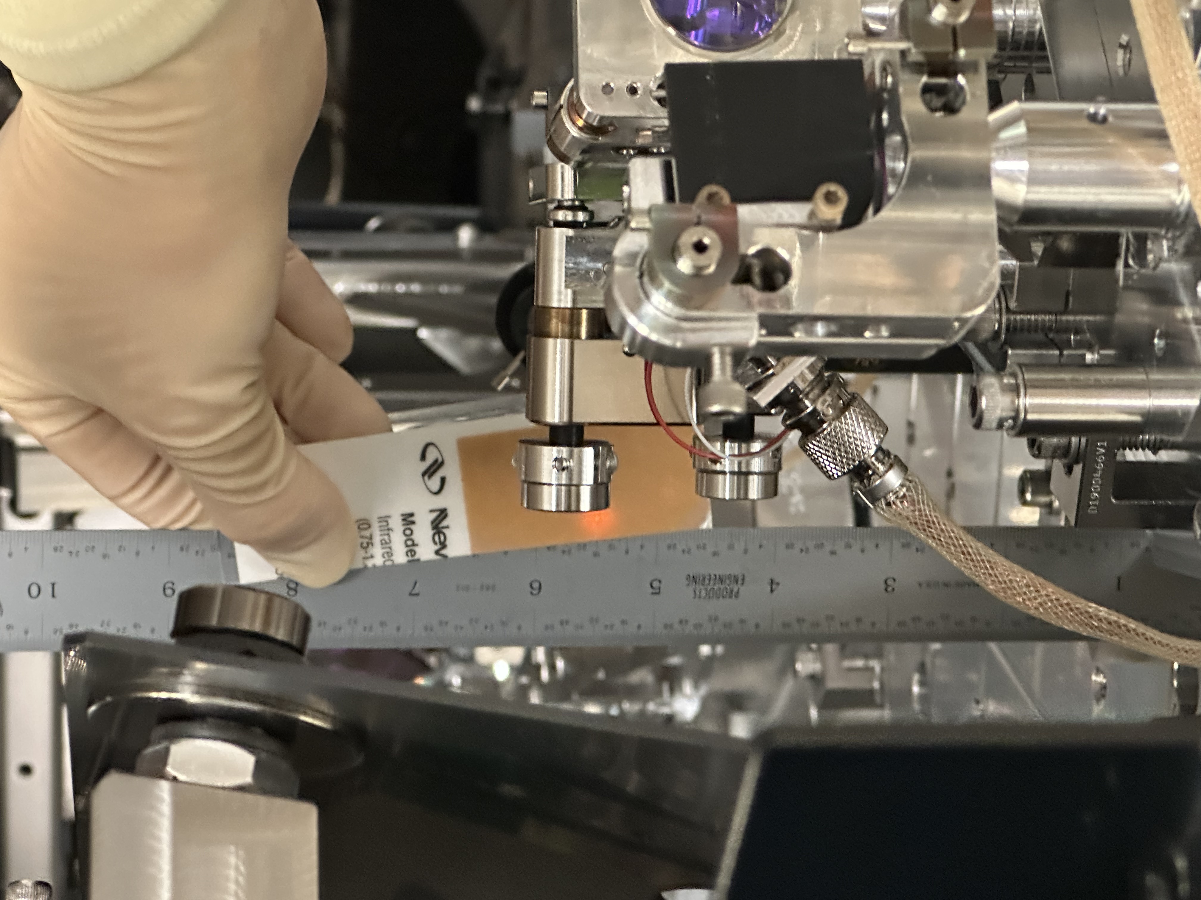
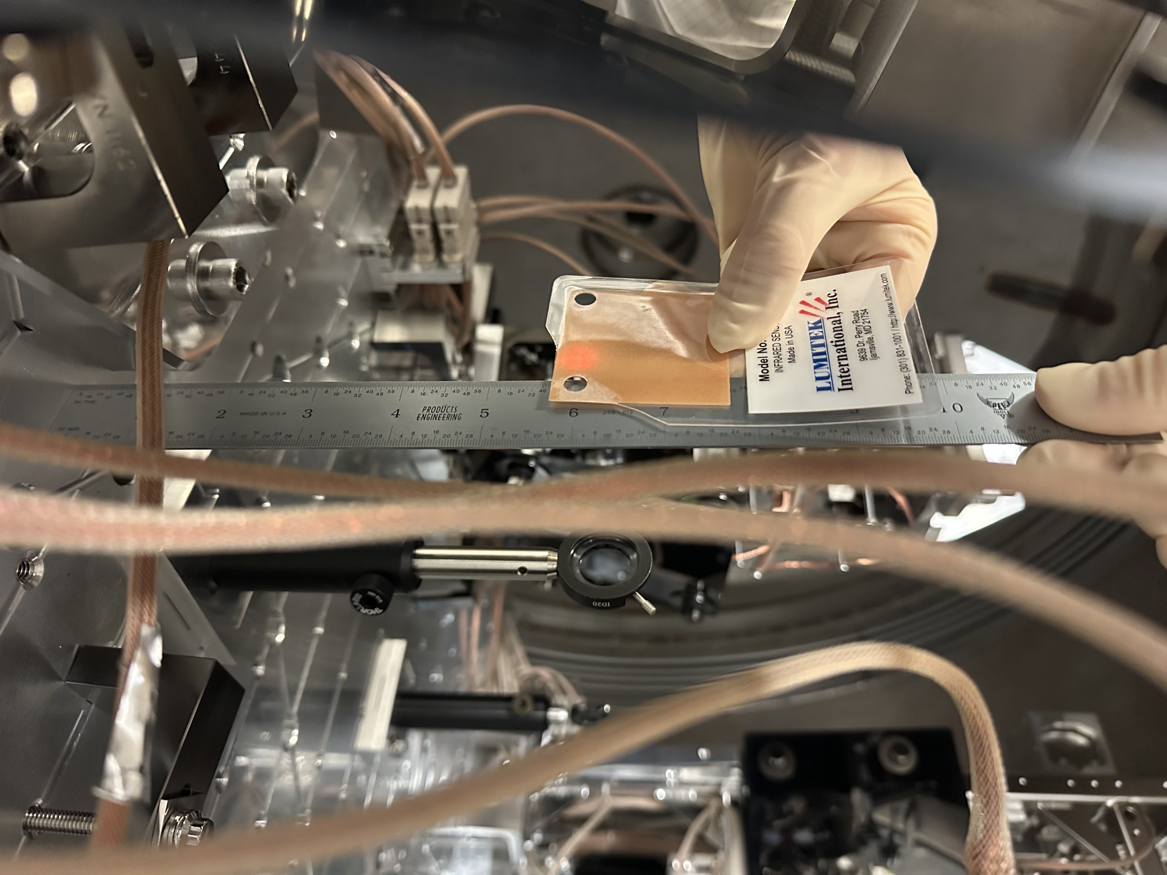
SPI Pathfinder ISIJ Shroud Removed
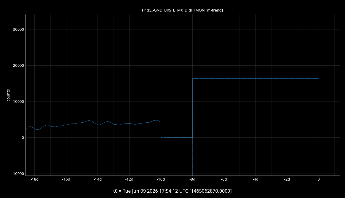
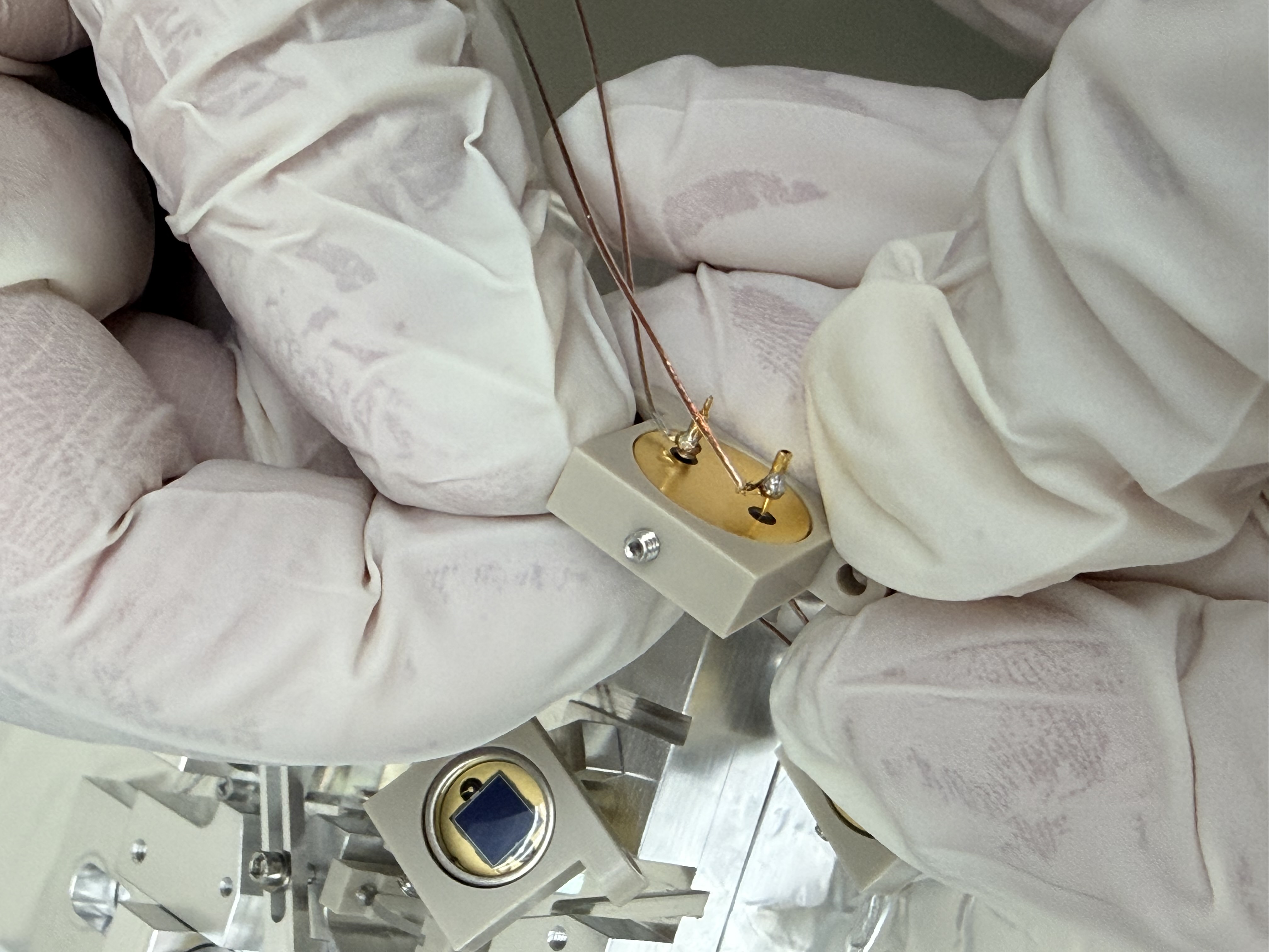
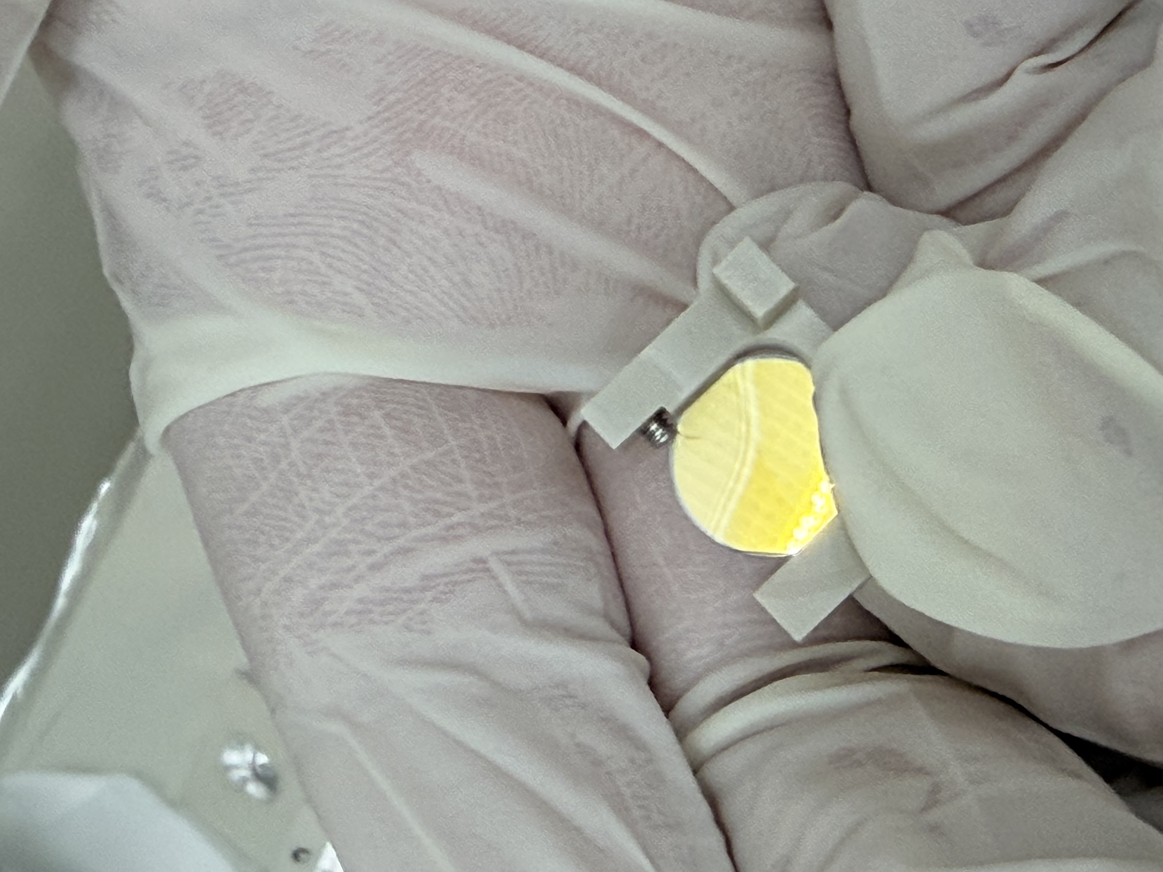
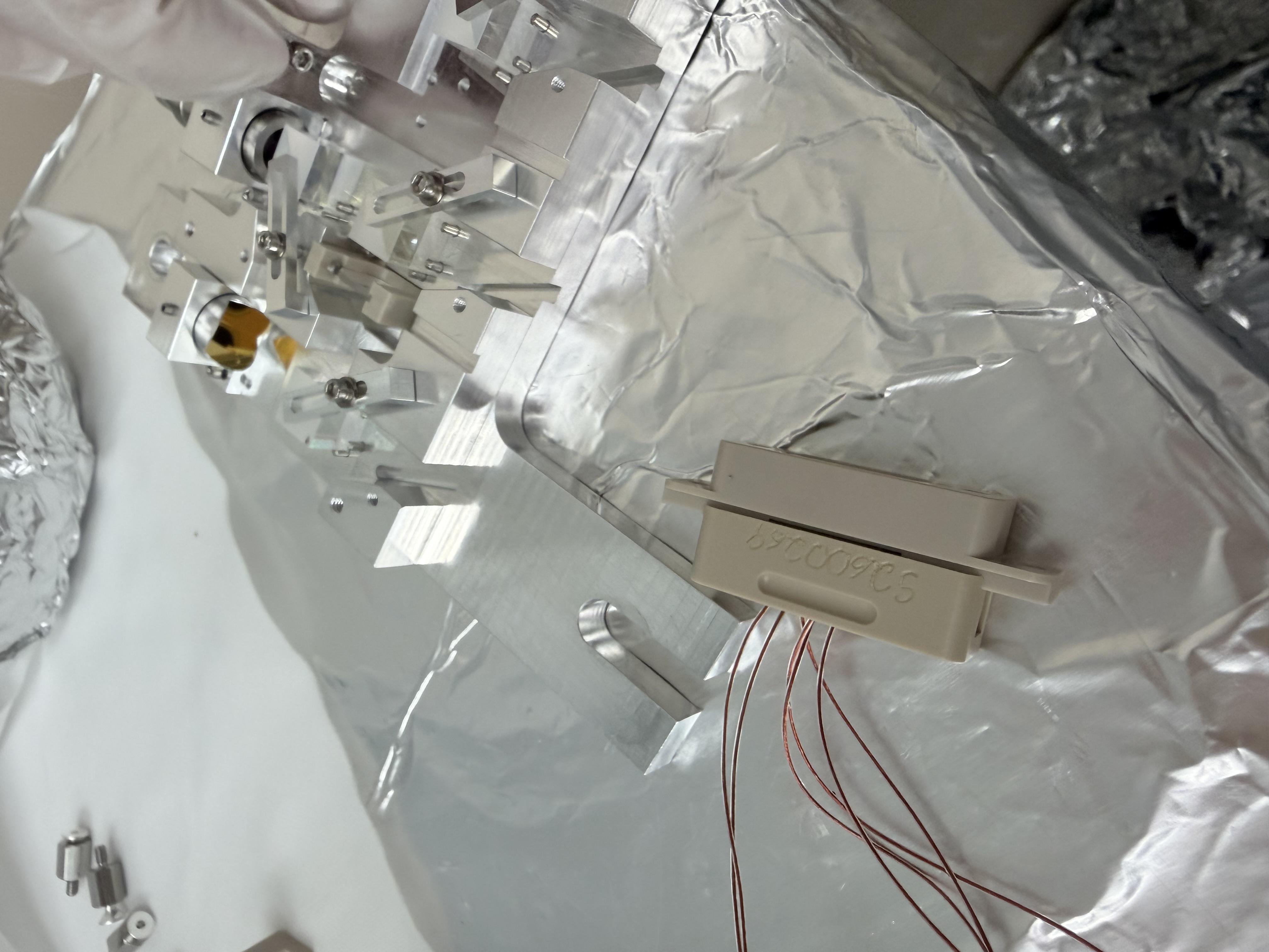
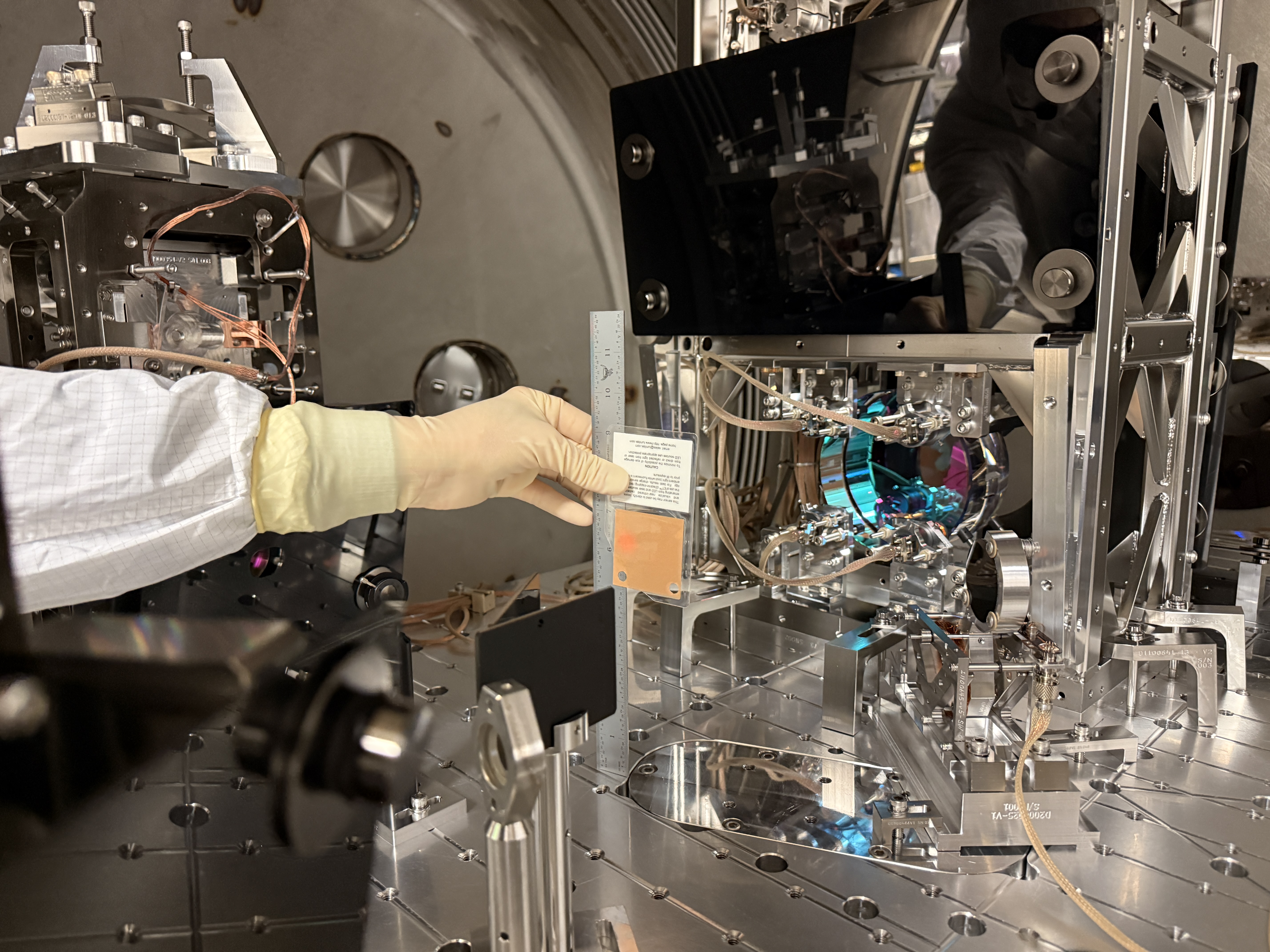
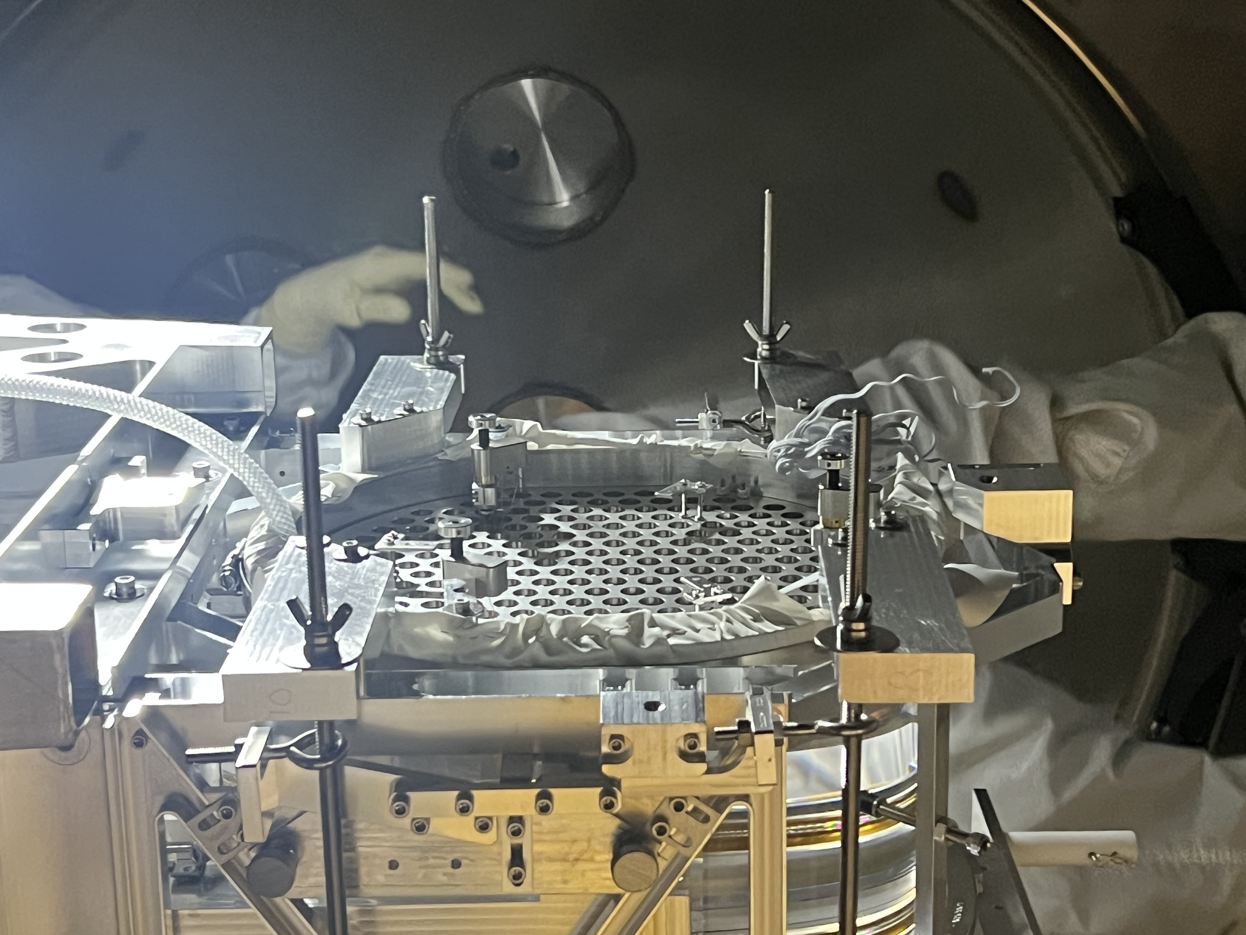
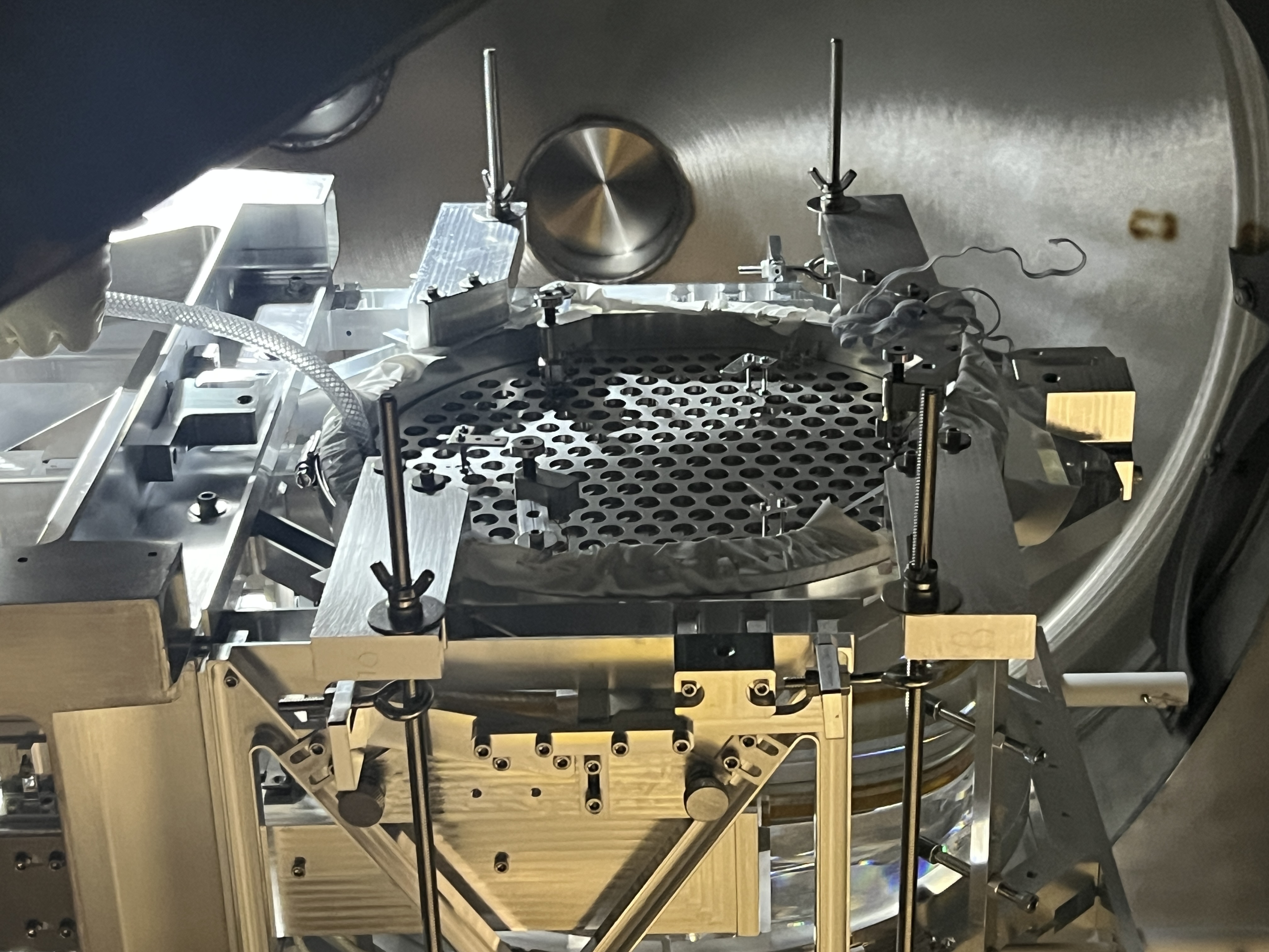
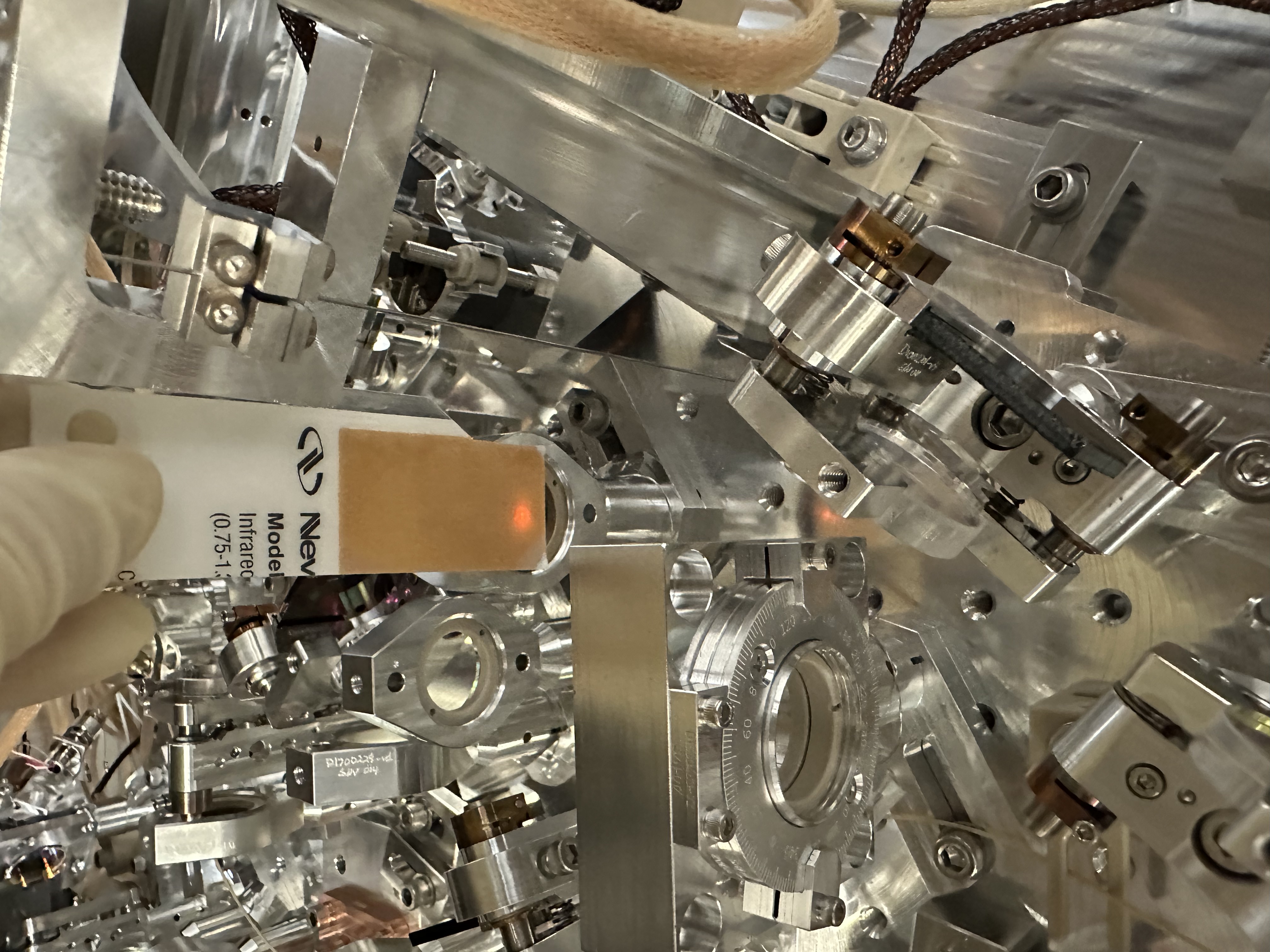
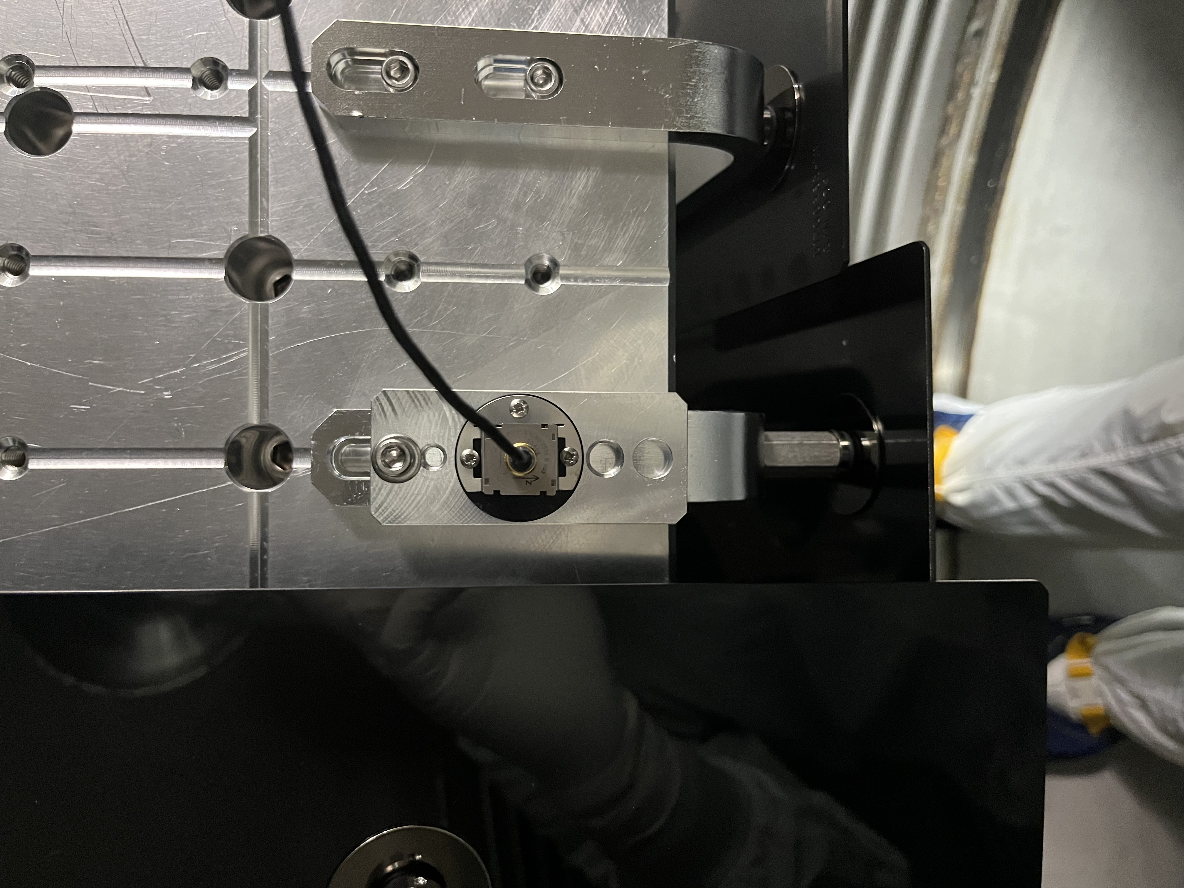
J. Kissel

Upon carefully reviewing the results of the BnK hammering (LHO:90493) of the SPI Pathfinder's HAM2 ISIJ Reflector's Shroud (D2500030 on the assembly D240010-v6) I've decided to remove the ISIJ shroud from the assembly for now. (Honestly, I made the decision to remove it right after hearing it; LHO:90544, but my desicion was supported by the BnK results).

Here's why:
    - The resonances are high-Q and below the required 150 Hz. Thus, if left as is, its frequency response would likely impact the force-to-displacement transfer function of the ISI, and limit the band-width of the ISI feedback control loops.
    - The argument the SPI team came up with for this shroud serving any "prevent scattered light into / from the SPI" purpose is weak, given that the very small solid-angle of possible reflection of 1064 [nm] light into/out the SPI system or the main IFO system (we guess that the tube would need to be ~meters long; but we haven't done any quantitative calculation).
    - The SLIC team has already looked at the HAM2 and HAM3 system enough to decide that carving out some portion of a circle on the existing, middle ISI table panel above the ISIJ reflector works for them. Similarly on the other end in HAM3 over the ISIK transceiver, the panel collection is enough. I hope they've done a what quantitative estimate they can; it's likely way more that the SPI team was capable of.
    - The arguments for this should as an "in-chamber work" protection mechanism is weak: Rarely (as in once every 5-to-10 years) do any humans find themselves *in* the mode-cleaner beam tube, +X of the HAM2 ISI, and it's with great intent. In addition, the ISIJ reflector assembly doesn't protrude that much that one's appendage would "get caught" on it. Finally, even if contacted, it's a very robust assembly. You'd need to soccer-punt it to move anything, and it's more likely you'd destroy your foot/shin than even cause an alignment shift in the components.
    - At least upon first attempt at path-finding, we want to minimize any use of damping material like viton to prevent any unwanted drift. But even if we damped the resonance, there would still remain a resonance, just lower Q, thus it might still be bad for the HAM2 ISI loops.

Eventually, we want to re-design this shroud to, say, add an end-cap. And eventually we can easily can hose-clamp a bit of viton like we've done for the, say, the ISI's GS13 vacuum cans.
We'll do that ... next time, if at all.
Comments related to this report
Images attached to this comment


Images attached to this comment