J. Kissel, C. Gray, M. Nakano, G. Billingsley
We're getting started with cleaning our 1" and 2" optics for SPI. Corey uploaded *all* of our optics (50:50 BSs, 85:15 BSs, TFPs, HR mirrors, Lenses etc.) to ICS in prep, and I reviewed the work double checking that the ICS record information makes sense. For the HR mirrors, which were part of the 2025 large custom purchase order (C2500044) from FiveNine Optics (to be used by JAC, SQZ, the LLO TNT Lab, and SPI), he entered them into ICS with a key that used the DCC number that's physically etched into the barrel of the optic.
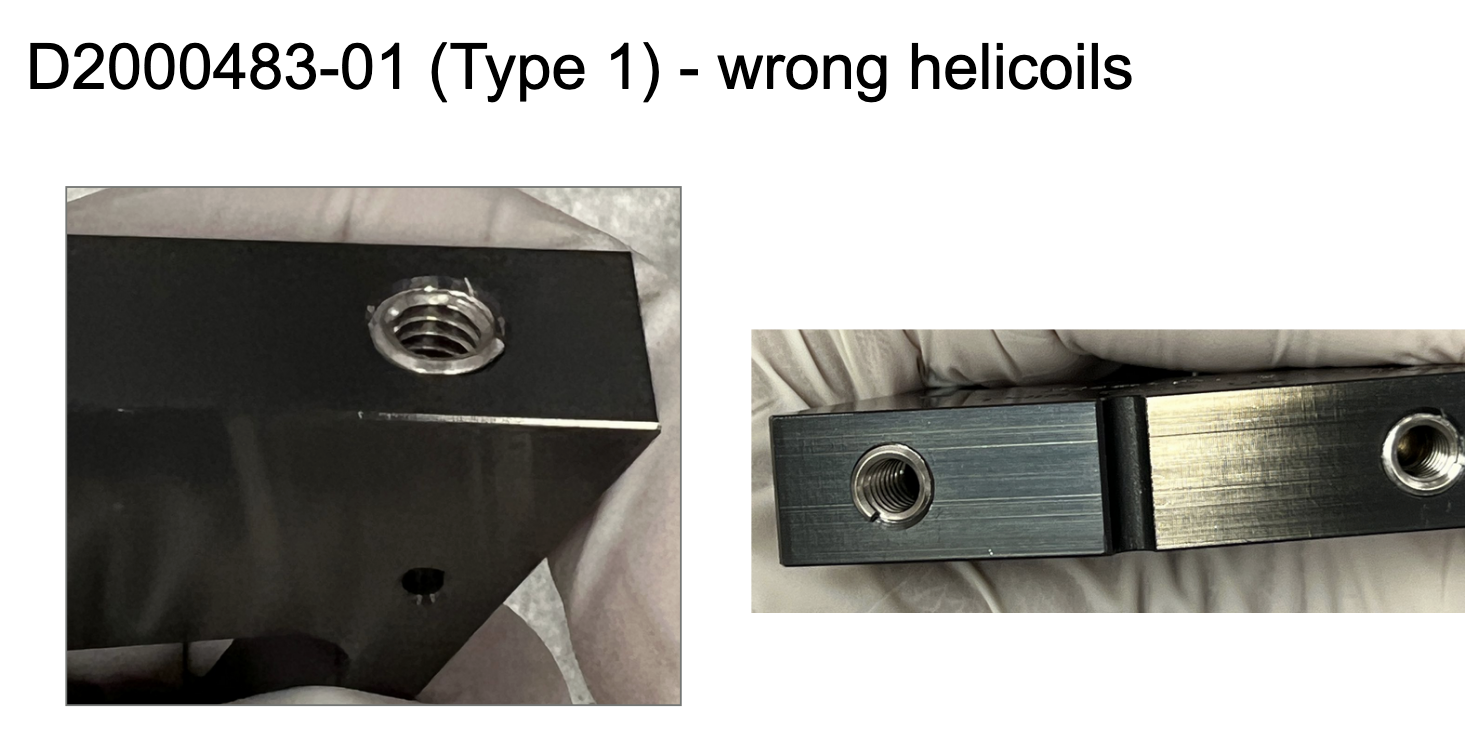
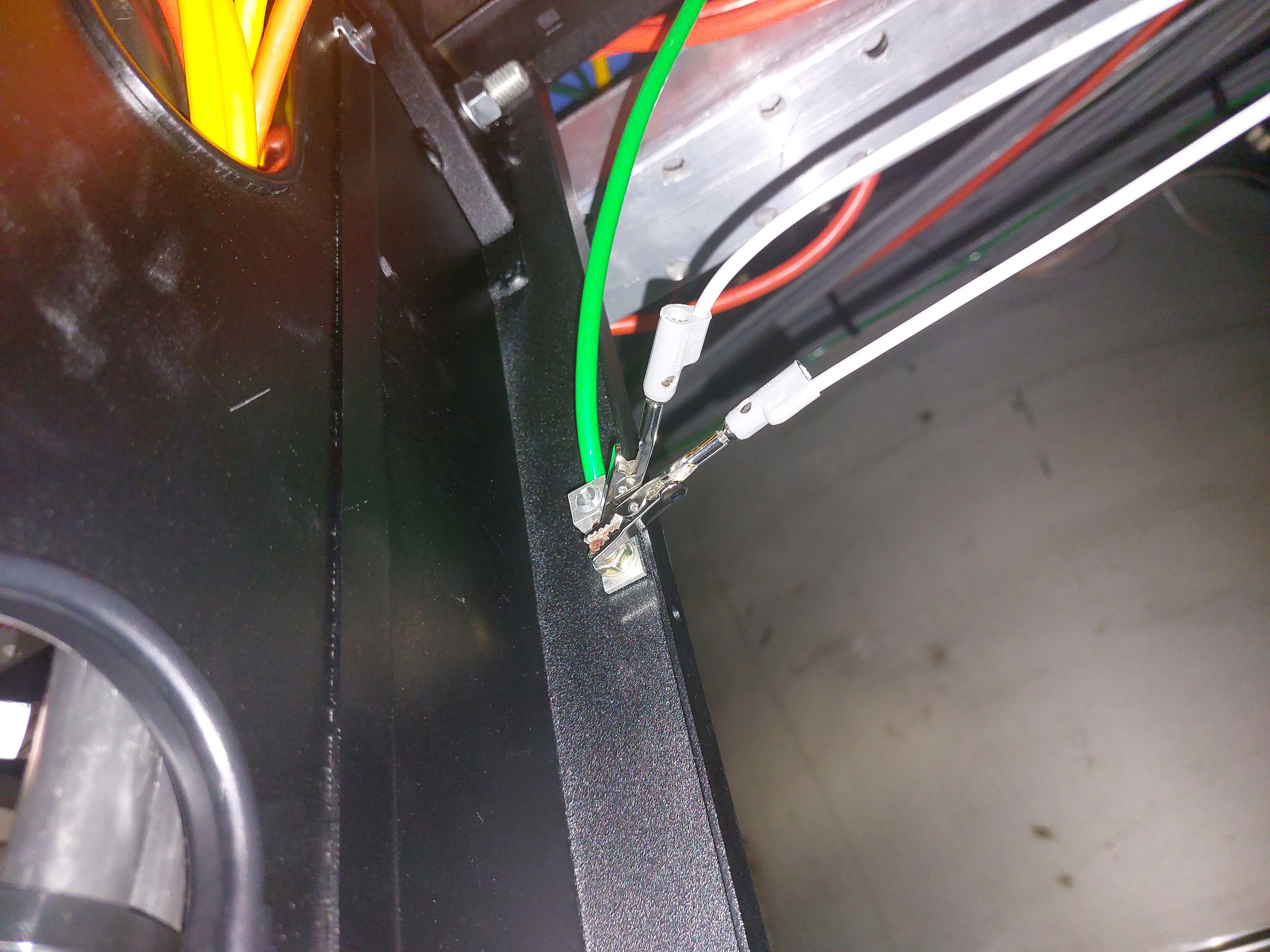
HOWEVER -- the DCC number etched on the barrel of the optic is E1900393 -- E1900393. See attached picture.
That drawing number is for the coating spec of 0-25 deg AOI HR mirrors.
The physical coating spec we want, was provided, and bought was for 45 deg AOI, i.e. E1900392 -- E1900392 (one DCC number lower).
So these HR optics, coated with E1900392 spec, bought with C2500044, which have vendor run numbers 1895 and 1897, have the incorrect DCC number for the spec etched on the barrel.
If you head to the purchase order, C2500044, and look at the FNO_4787-1.pdf attachment, it clearly states (twice!)
"[...] per drawing E1900392-V2. Serialization per E1900392-V2."
However, if you then *read* E1900392-v2, section 8 states equally clearly
"Each optic should be serialized and marked with the following code/description:
1" optics: E1900393-v2-01 S/N:01 HR1064+532
with incremental S/N: 01, 02, 03, ...
2" optics: E1900393-v2-02 S/N:01 HR1064+532
with incremental S/N: 01, 02, 03, ..."
Thankfully we know the coating is the correct E1900392 coating --
(1) The PCAL team confirms via measurement at 45 deg AOI, that these have transmission at the level of ~5e-5 W/W, so these will serve excellently as HR mirrors at 45 deg AOI. See LHO:86699
(2) The vendor's data, posted to C2500186, (Even though the run numbers listed on the first page of the data for the First Batch are quoted as "V2-2895" and "V2-1897" we know the run numbers are V2-1895 and 1897 from what's written on the containers the optics came in; see attached picture) show figures with captions indicating the data is from AoIs of 38, 45, and 50 deg, a reasonable range of AoI's to test for a 45 deg AoI mirror; and conversely no measurement of anything at AoIs less than 25 deg, which would be what one would report for a coating that's spec'd with the *actual* E1900393 spec.
(3) The E1900392 spec specificies a 45 deg AoI.
So, now we just have to figure out how to keep track of this information when we're in the lab / in the chamber, 5 years later, and the optics are no where near their cases and a brand new person is using the optics. C'est le vie!


There is a H0:FMC-CS_WS_RO_ALARM on CDS_OVERVIEW
Tyler has the RO system offline at the moment, further work will be done on it today. Cellphone alarms for this channel are currently bypassed.