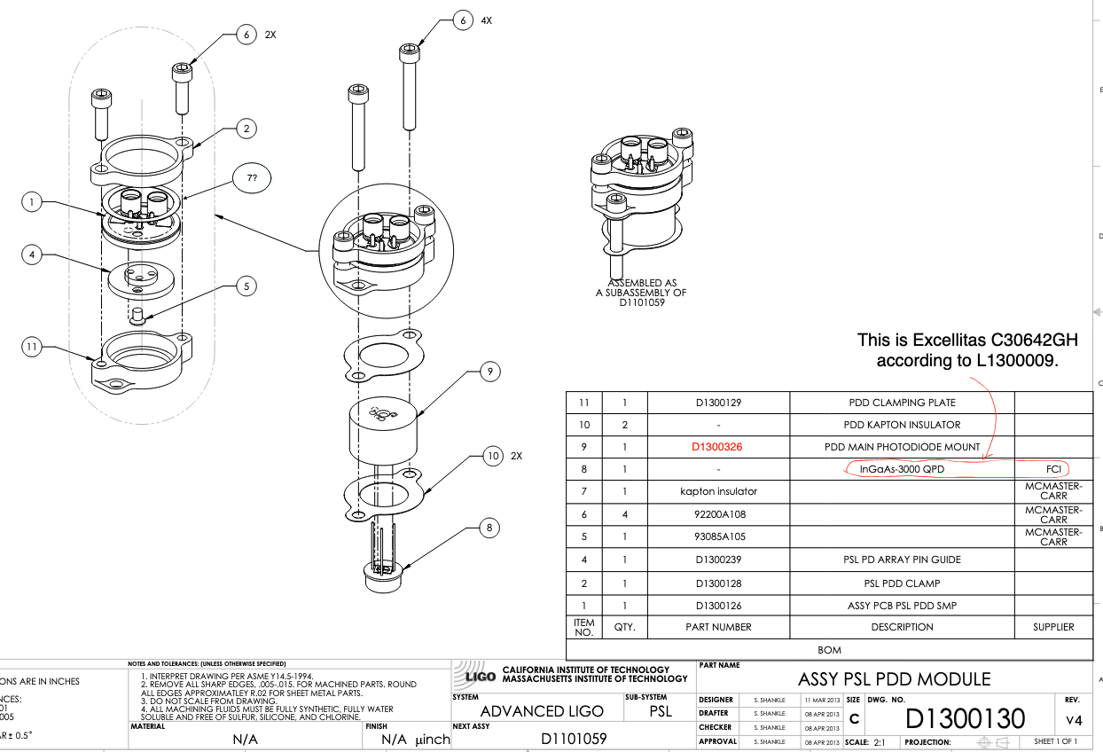
First attachment is a screenshot of D1300130 ISS array PD assembly (which is somehow called "PSL PDD MODULE").
Each PD (part #8) is entirely retained in an aluminum cylinder called the PDD main photodiode mount (part #9) and therefore the can of the PD is conductive to the cylinder. However, the cylinder is supposed to be isolated from the ISS array plate (and therefore the entire ISS array structure) by two pieces of kapton insulators (part #10). PCB assembly, which is connected to the PD, is sandwiched between two aluminum clamps (part #2 "PDD clamp" and part #11 "Clamping plate", which I refer to the bottom and the top clamp respectively), but the PCB ground is isolated from the clamps by an insulator ring (part "7?").
This way ground loop is broken even though the can of the PD is connected to the shield of two SMP coax cables on the PCB board (part #1).
Rahul and I checked the continuity between the cylinder and the ISS array cage. (Note that this check could not be done without disconnecting all SMP cables from the preamp first, because the preamp's ground is somehow connected to the optics table, which is connected to the ISS array cage.)
Issues found on the installation spare:
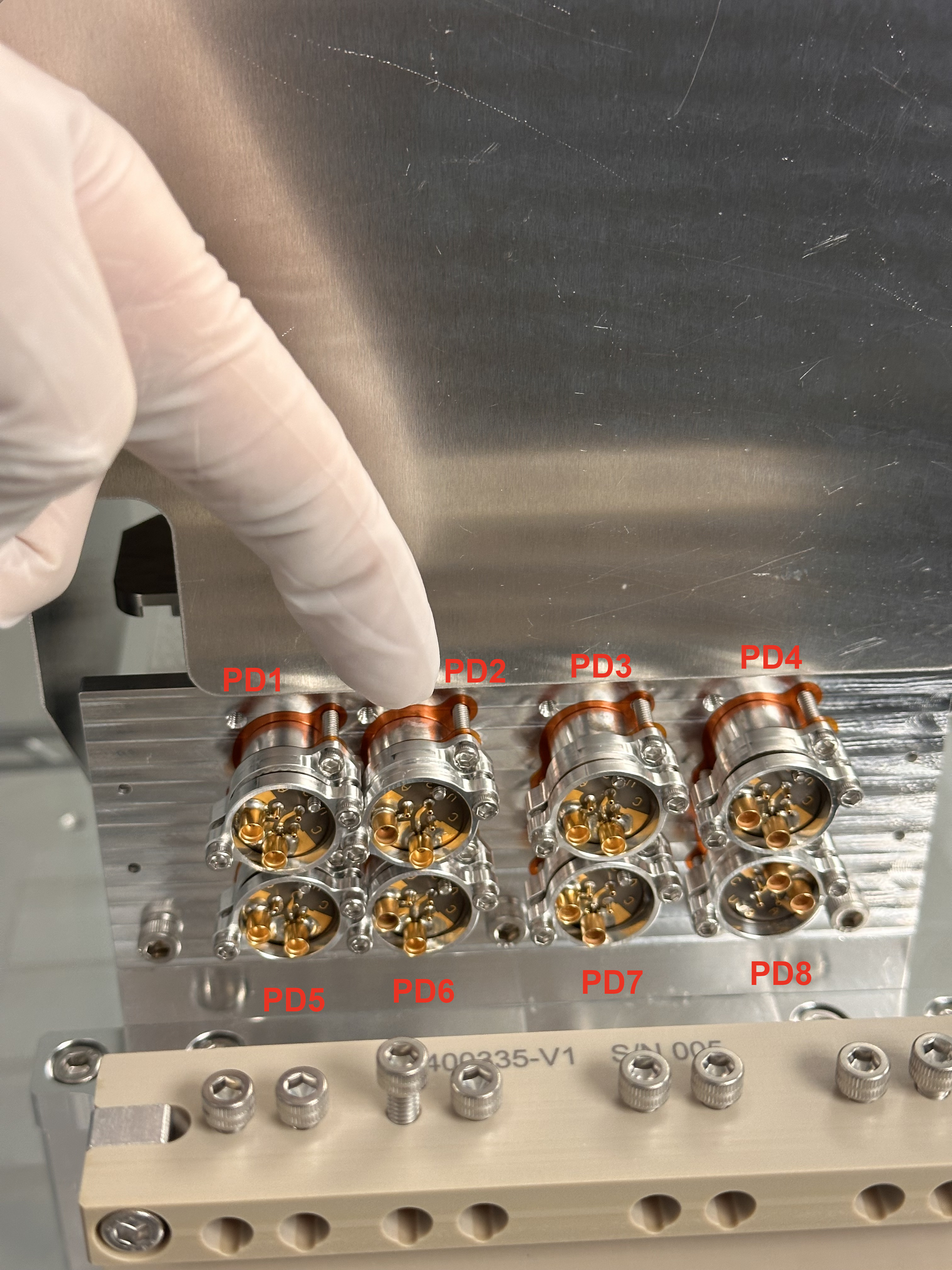
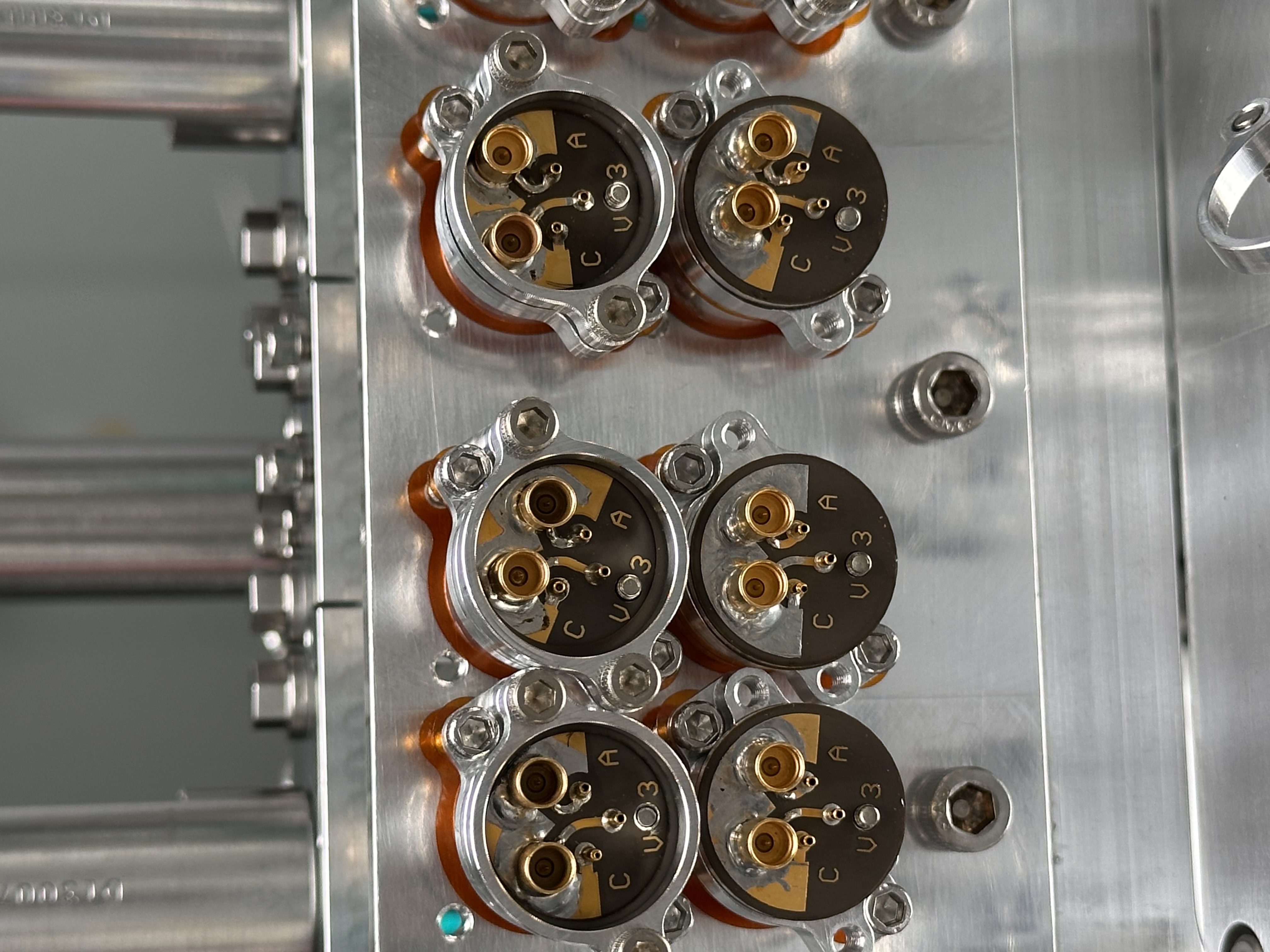
Unfortunately two of the PDs on the first floor (PD 5 and 6 in our notation in the lab, see the 2nd picture for the notation even though that is the picture of the 3IFO unit) didn't pass the check.
We also checked the grounding of the QPD and it was good.
Inspecting 3IFO, finding the same issue, and fixing it:
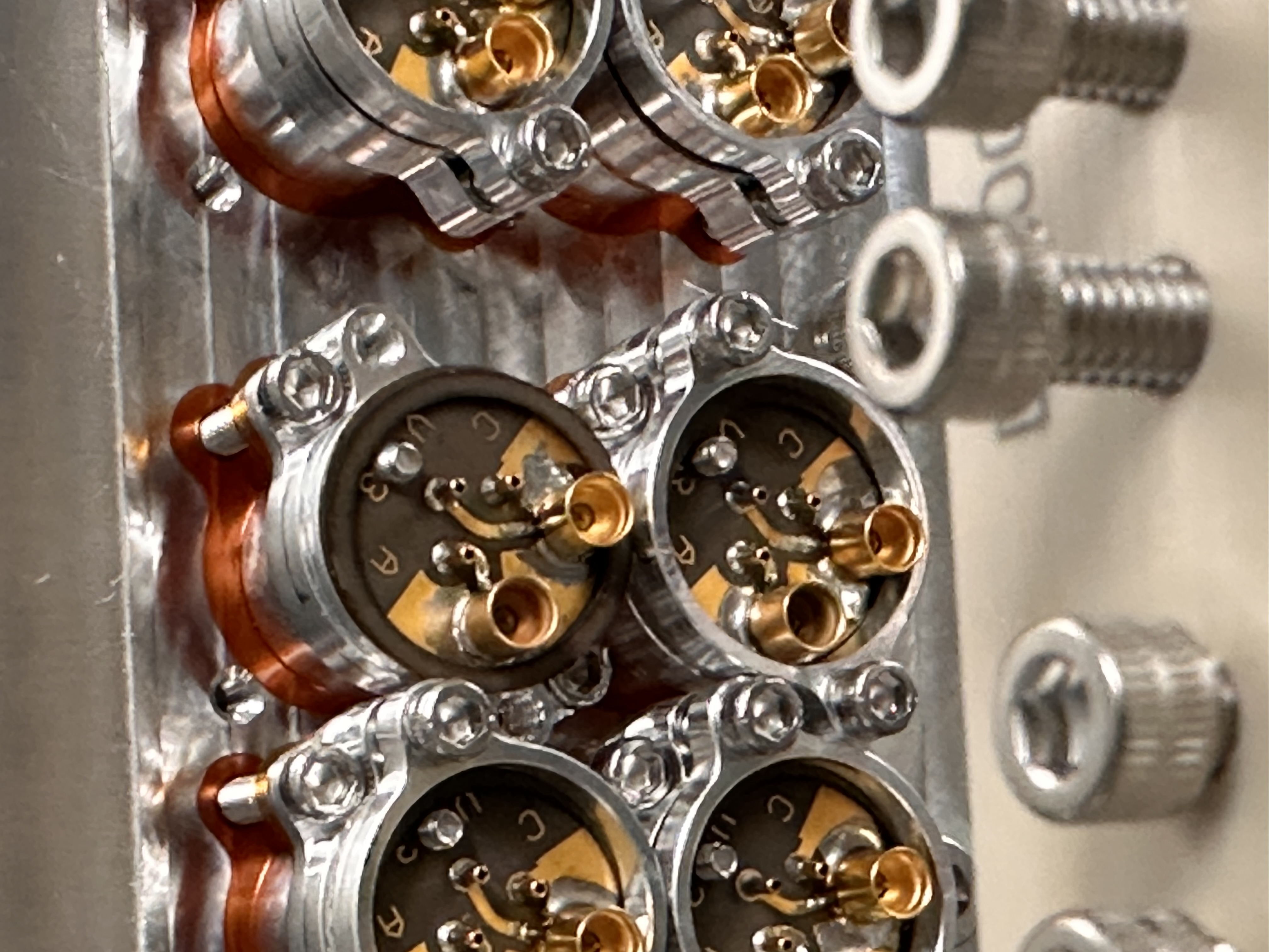
We quickly checked the 3IFO unit too and found that it also had a grounding issue for one of the PDs (PD 2). In the 2nd attachment, you can see that the space between the top and the bottom clamp of PD2 is smaller than the others.
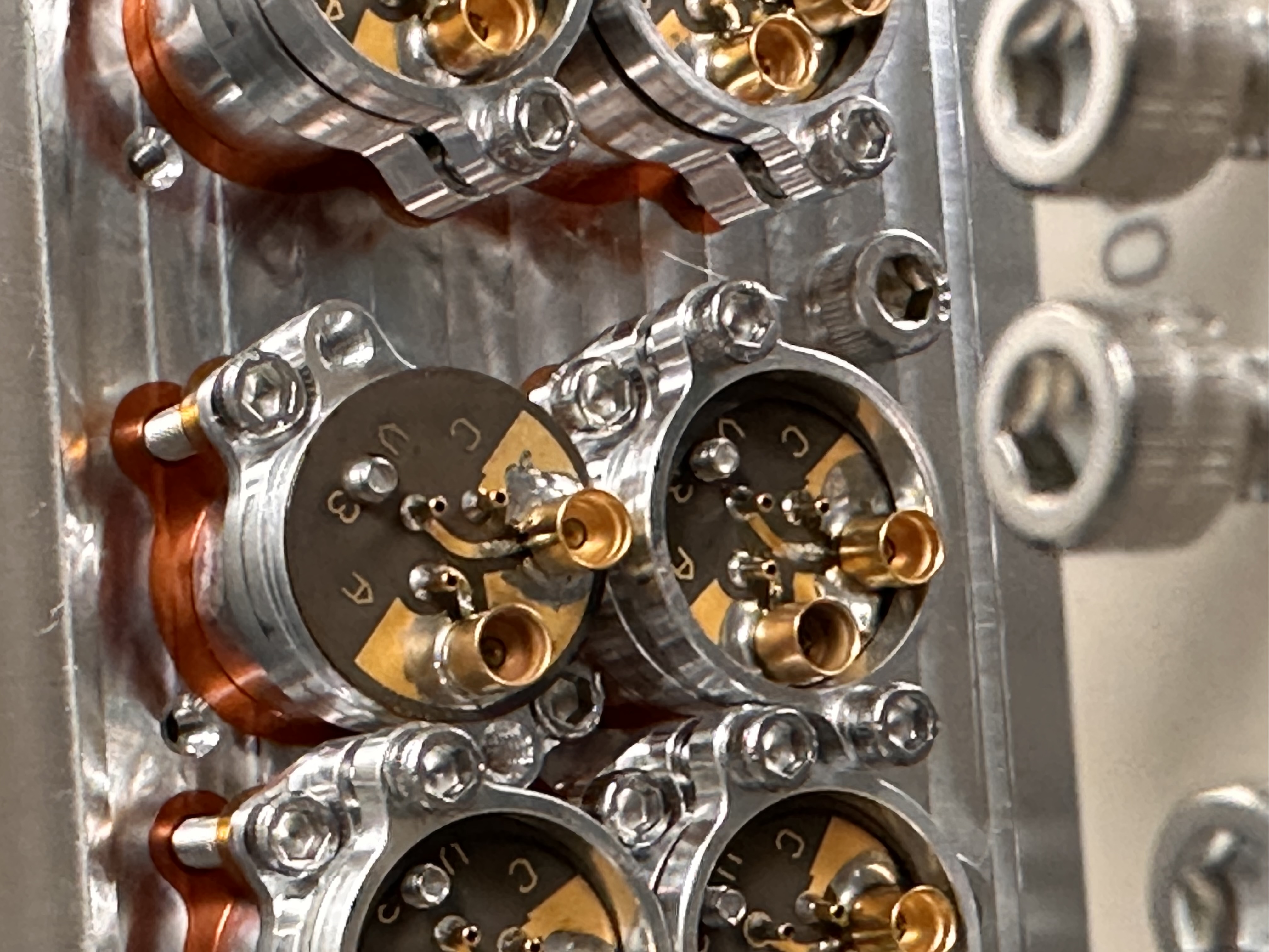
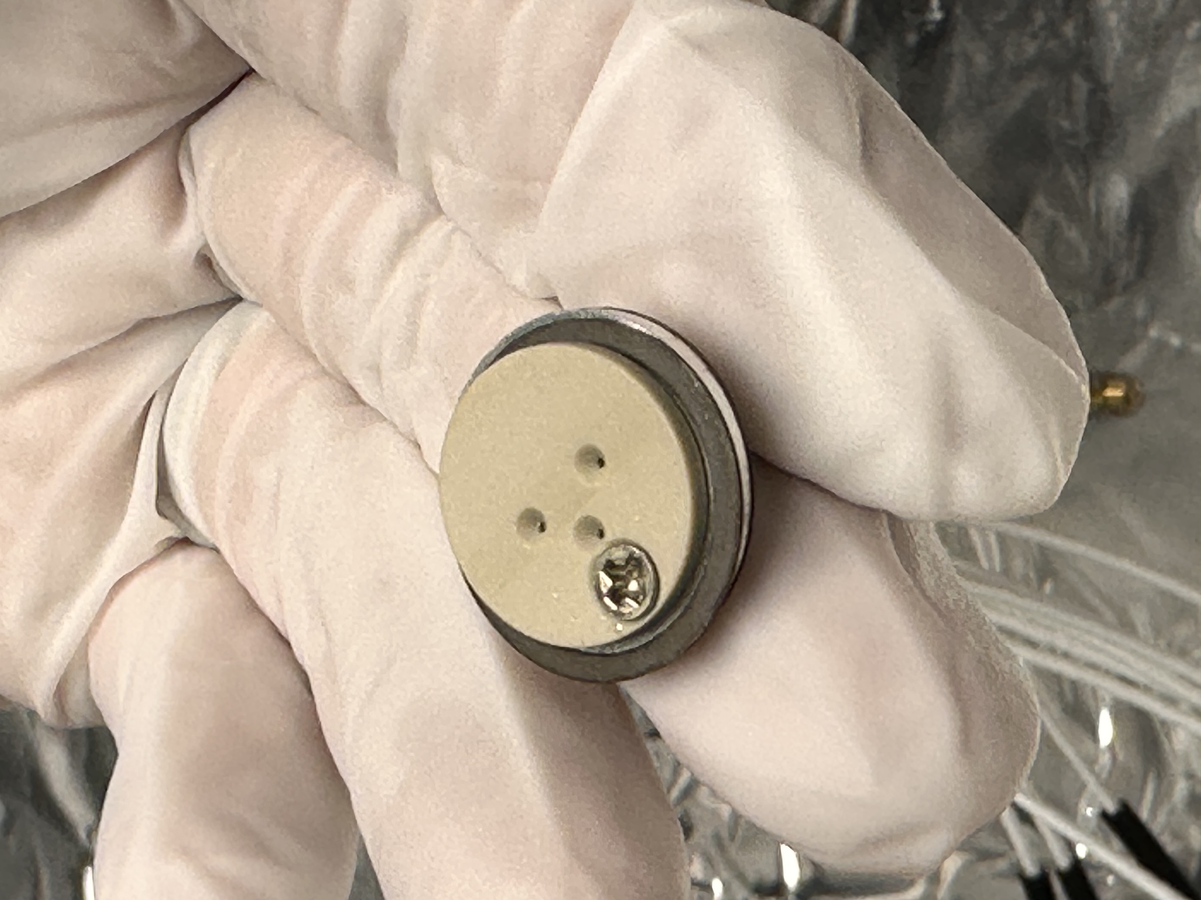
We removed the top clamp and found no insulator (3rd attachment). We disconnected the PCB from the PD and learned that:
- Disconnecting the PCB won't change the PD position. PD is somehow firmly attached to the main photodiode mount, and it won't shift unless we loosen the bottom clamp.
- The insulator was found on the other side of the PCB, between the PCB assy and the PEEK pin guide (part #4).
- Installing the insulator on the correct side (4th attachment) and reinstalling the top clamp, the grounding was broken.
Fixing the issue on the installation spare:
With the new knowledge about the insulator, we looked at the gap between the top and the bottom clamps of the PDs for the installation spare unit and it looked like PD5, 6, 7 had the insulator on the wrong side of the PCB even though PD7 didn't have the grounding issue.
Sure enough, we removed the top clamp for these problematic PDs, found no insulator for any of these (5th attachment), removed the PCB and found the insulator on the wrong side (6th attachment shows you one example), installed them correctly and the grounding problem was gone.
Electrical test:
Since we have disconnected the PCB and reconnected to the PDs, we reconnected all of the PDs to the preamp again and confirmed that all PDs still respond to the light as they used to.
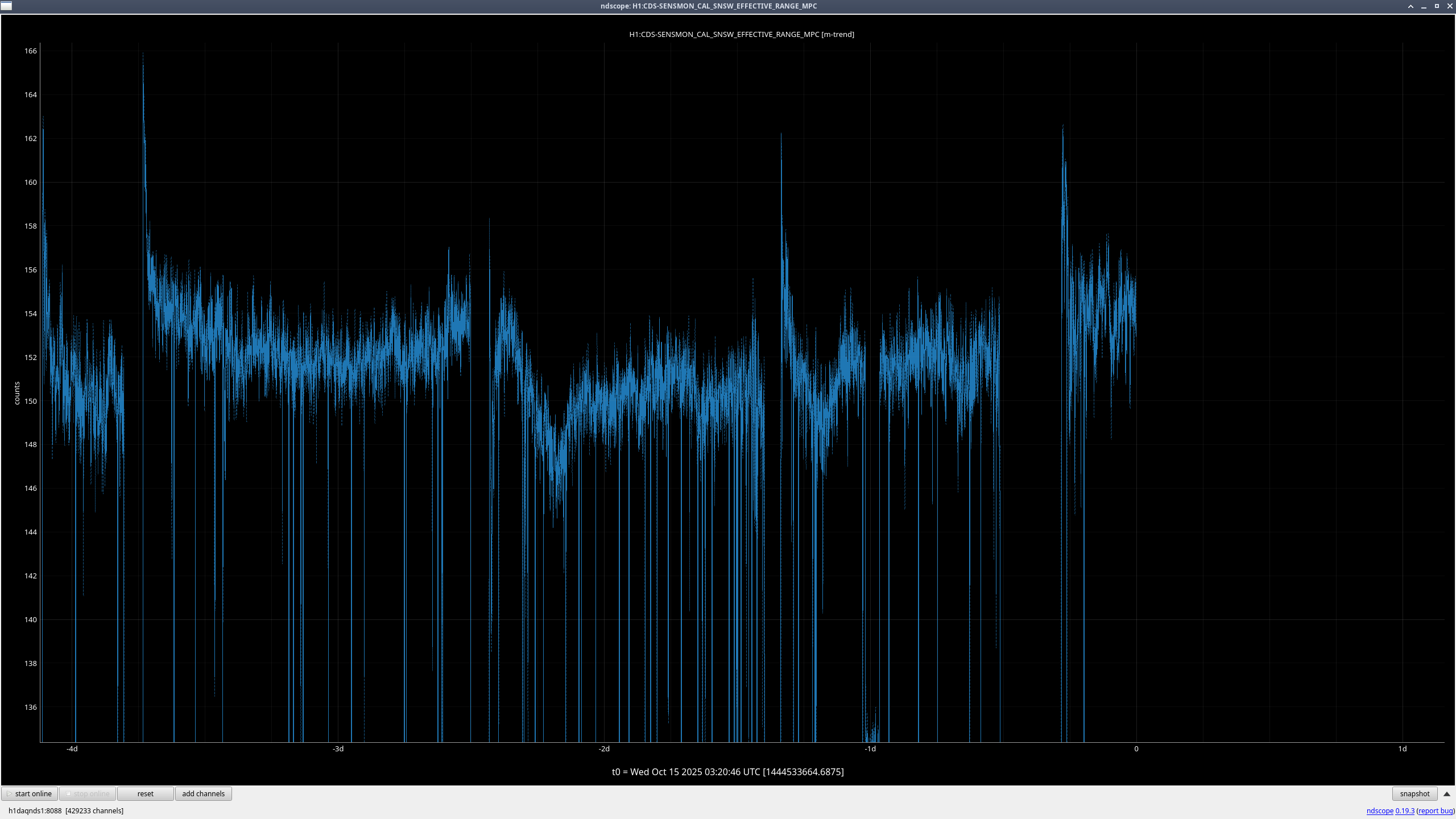
We haven't measured if any one of these are much noisier than the others, which we'll check later.