Belated, as usual.
Things make more sense, no railing of RM2
We continued HAM2/3/1 alignment. Things are making more sense now after realizing that RM1 and RM2 slider polarity was wrong but we're still finding things.
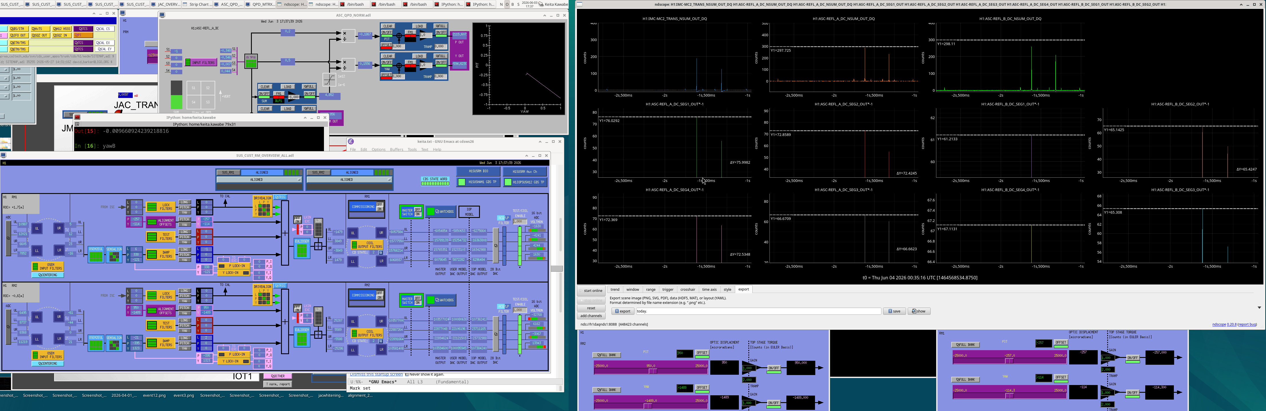
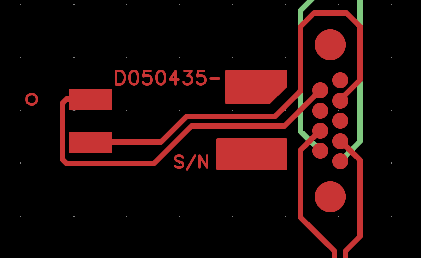
1st attempt: We rotated IM1 to relieve RM2 YAW (IM1 y -987->-687 i.e. +300 from Tuesday value), aligned PRM so the beam retroreflects (but didn't touch up other IMs in the interest of time). After some confusion it worked and we were able to center REFL ASC sensors without railing RM2. Happy. (See ASCREFL_centered_RMs_dont_rail.png. If you do the math using flash peaks, REFL_A PIT=0.034, YAW=0.013, REFL_B PIT=-0.0097, YAW= -0.017, so it was very good.)
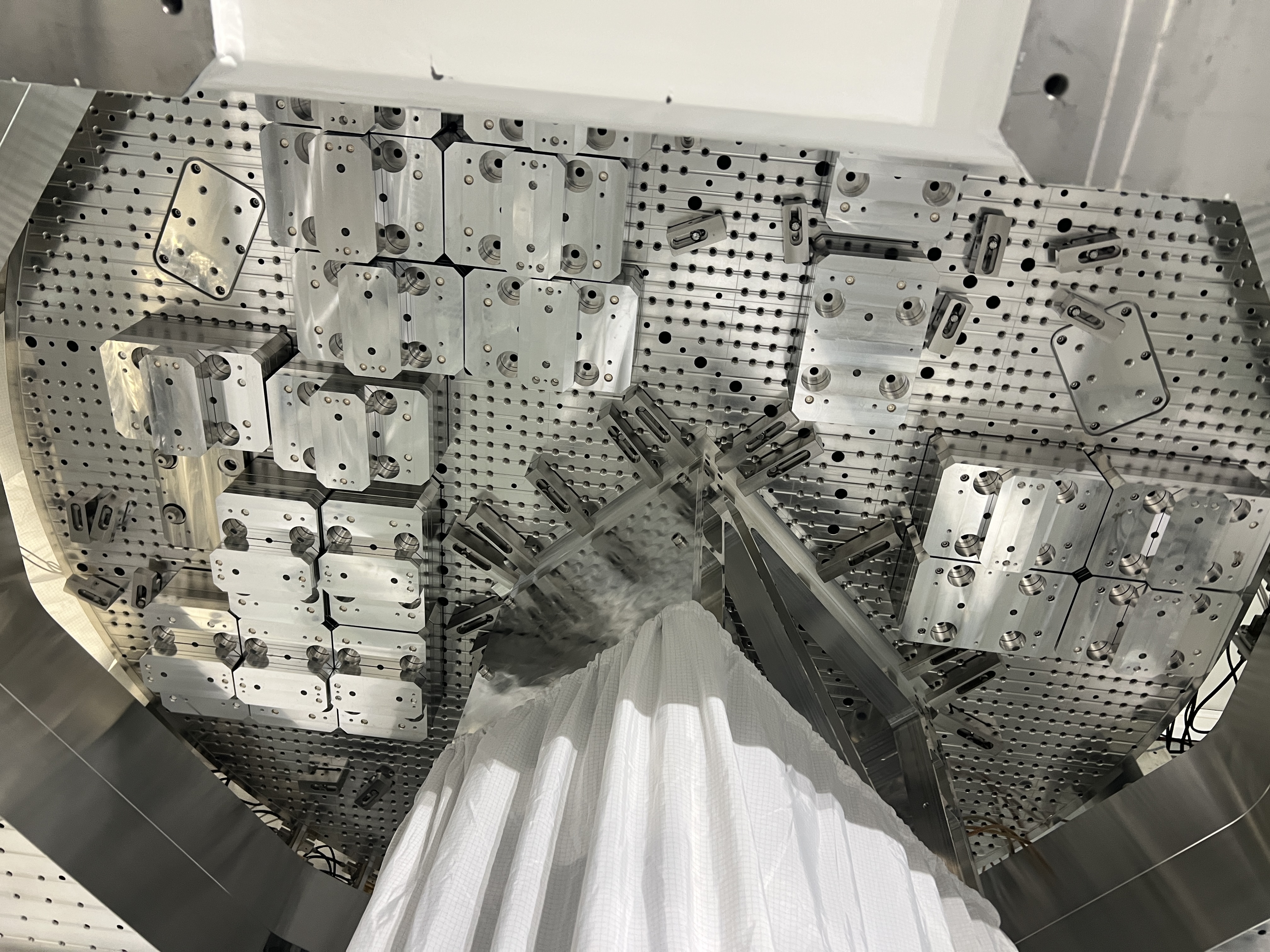
2nd attempt: Encouraged, we proceeded to center the beam on the IFI output baffle using IM2, steer the beam to the nominal beam position in front of PRM using IM3, steer the beam to the nominal position in front of PR2 using IM4 (which moves the beam position on PRM by a small amount but we didn't bother to iterate), and finally aligned the PRM so the retroreflection is restored. We were able to center REFL ASC sensors without railing RM2. Happy again. (eod.png, REFL_A P= 0.034, Y=-0.009, REFL_B P=-0.023, Y=-0.022.)
We looked at the beam position on IFO REFL baffle and it was off in YAW, so we changed the baffle position slightly in +Y direction.
Large difference in RM2 DAC output for two attempts, 80% or DAC range used in the 2nd attempt
We didn't change IM1-IM2 line, which means that the alignment into HAM1 should not have changed assuming that the PRM was retroreflecting, but the YAW offset necessary for RM2 to center the ASC sensors in the 1st and 2nd attempt were very much different.
| all numbers are in urad |
1st attempt
(PRM P, Y = -1165, 320)
|
2nd attempt
(PRM P, Y= -1165, -300)
|
2nd [P,Y] - 1st [P,Y] |
| RM1 [P, Y] |
[-243, -45.3] |
[-257, -114] |
[-14, -68.7] |
| RM2 [P, Y] |
[930, -989] |
[950, -1489] |
[20, -500] |
In the 2nd attempt, RM2 Y offset changed by negative 500urad and the DAC output of two of the RM2 coils reached ~107 million, which is about 80% of the DAC range. That's closer than I'd be comfortable with before closing down the chamber.
That's consistent with the retroreflection error
It turns out that this is consistent with our retroreflection accuracy which I claimed to be "like +-50urad" in PRM rotation (not the beam rotation) in alog 90451.
Equivalent of positive PRM rotation of 50urad in YAW is replicated by the combination of physical negative 55urad for RM1 and physical negative 380urad for RM2 (note that the sliders for RMs as of now has the opposite sign as the physical rotation).
If retroreflection is off in terms of PRM YAW rotation by +-50urad, when the REFL ASC sensors are centered, RM2 YAW would be off by +-380urad from what would be required to center the beam that is truly retroreflecting. See attached script. 500urad difference between two attempts is consistent with that.
On top of that, it's possible that +-50urad error estimate is too optimistic. We set the PRM angle by centering an iris (placed between IFI input and IFI HWP) to the forward going beam and centering the back propagating beam on the back of the iris. The basis for the accuracy is that we could start seeing how the circumference of the back of the iris is unevenly illuminated by the back-propagating beam when we gave the PRM 50urad offset, but the beam is always moving in YAW and sometimes rather slowly, so we have to eyeball the average beam position.
We don't know if the 2nd attempt was closer to the true retroreflection or, for that matter, if the true retroreflection is "on the other side of" the 2nd attempt relative to the 1st.
As such, it's prudent to relieve RM2 YAW offset further.
Tomorrow
Relieve RM2 further by giving IM1 a positive 300urad YAW rotation. IM2, IM3, IM4 and PRM should be readjusted accordingly.
IM1 YAW offset hasn't changed much in the past 2 years except for this week, and we'll go back to that neighborhood. Even though this means that the beam on IFI input baffle will be off-centered (probably it's been like that for years), I'm absolutely sure that the forward-going beam won't be clipped, I'm also quite sure that the clipping-like thing of the IFO REFL beam on the IFI input baffle won't come back as far as PRM is retro-reflecting.
We might have to move the IFO refl baffle again.
We WILL move the IM4 baffle because whenever the beam is aligned to the nominal position in front of PRM the beam is too close to the +X edge of the baffle.


