Elenna Capote, Camilla Compton, Sheila Dwyer, Derek Davis
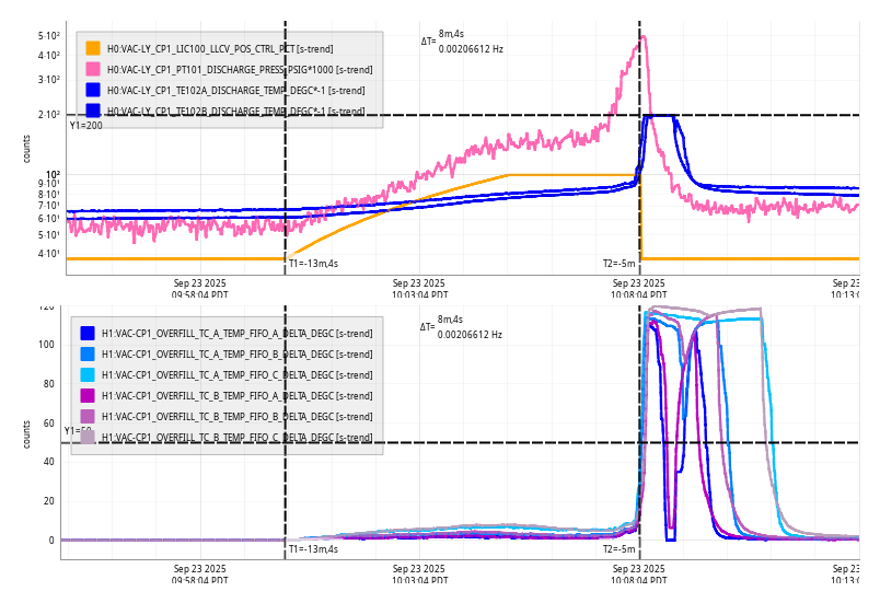
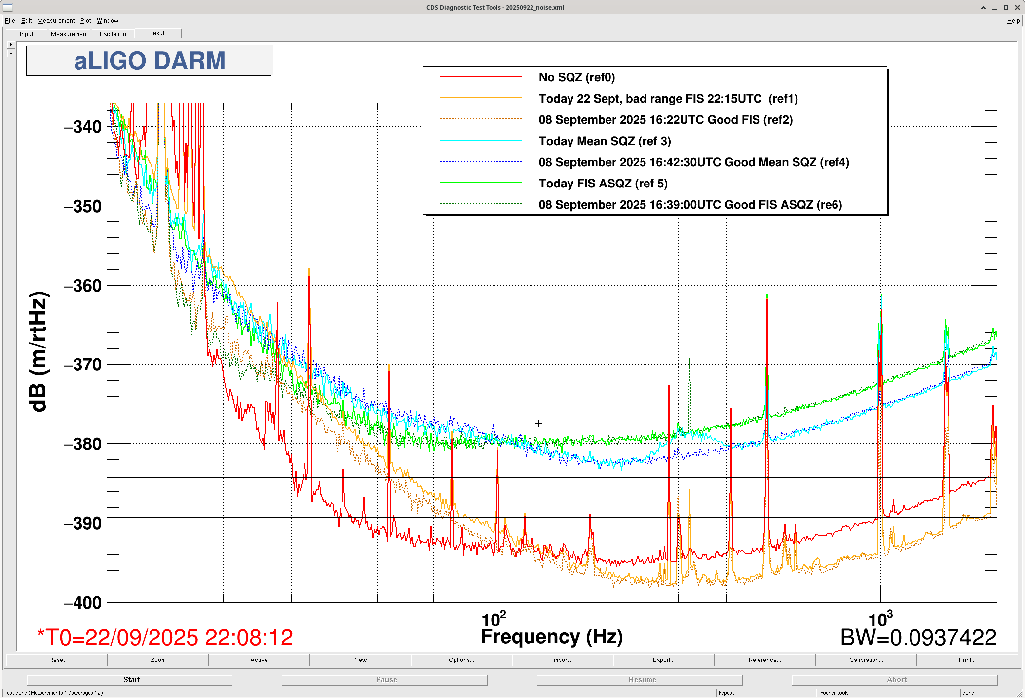
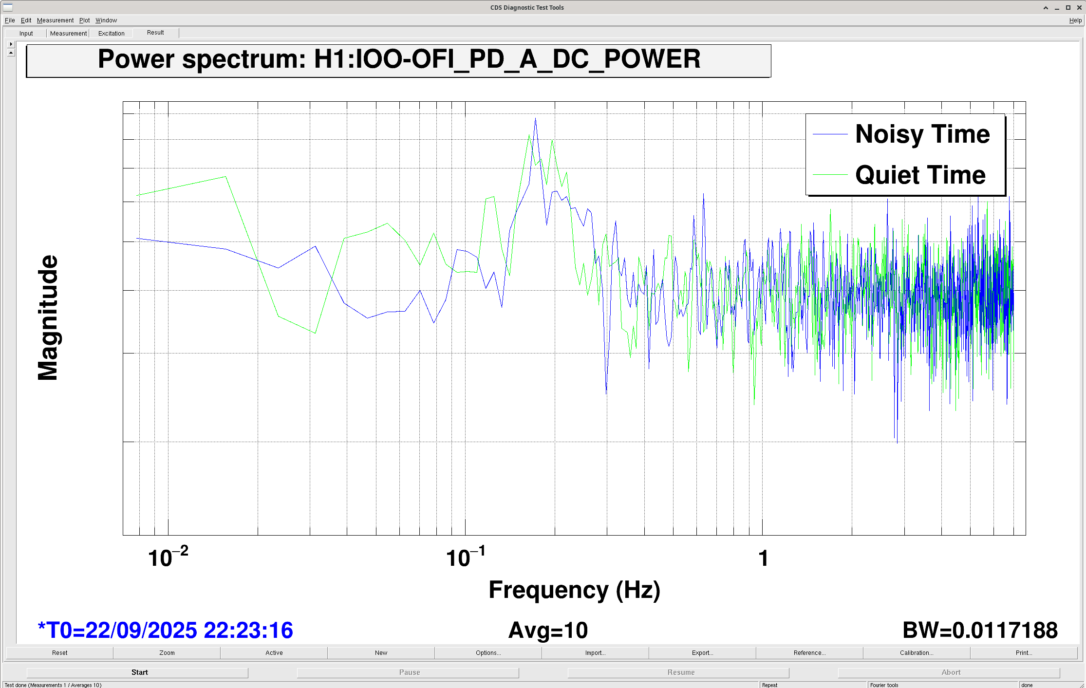
This afternoon we had a repeat of the bad low frequency noise that we have been suspecting was from filter cavity backscatter 86596. We saw that the symptom of elevated noise in the filter cavity error signal was similar to previous incidents plot.
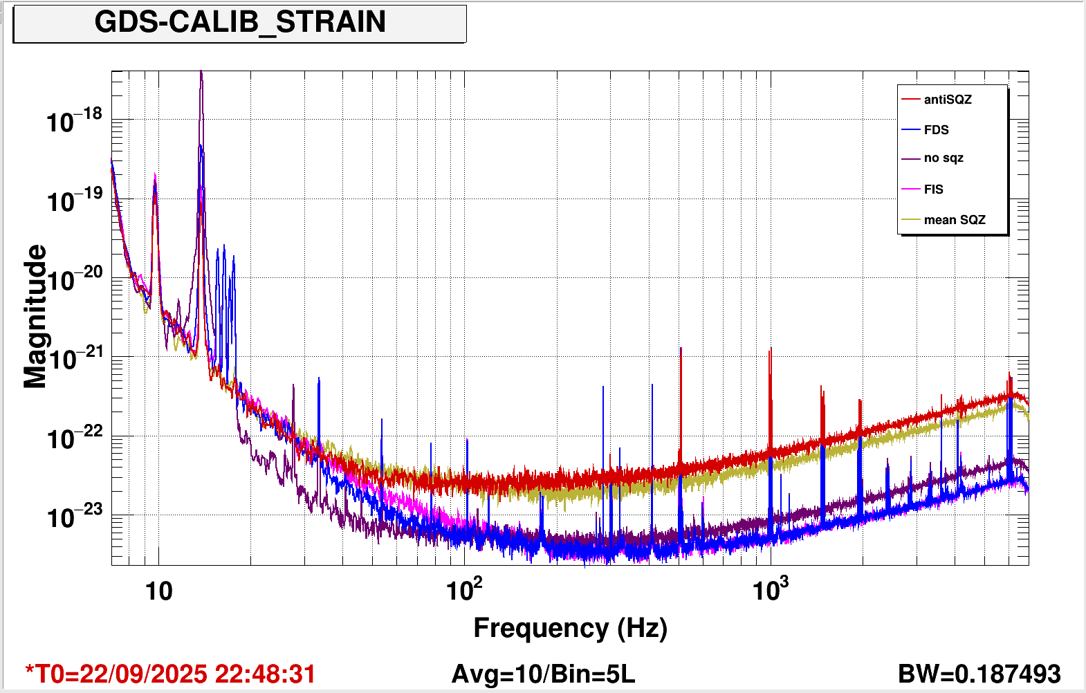
We compared squeezing with and without the filter cavity, and no squeezing, and see that this noise is there when squeezing is injected no matter what the filter cavity state is. plot and plot with mean sqz and anti squeezing.
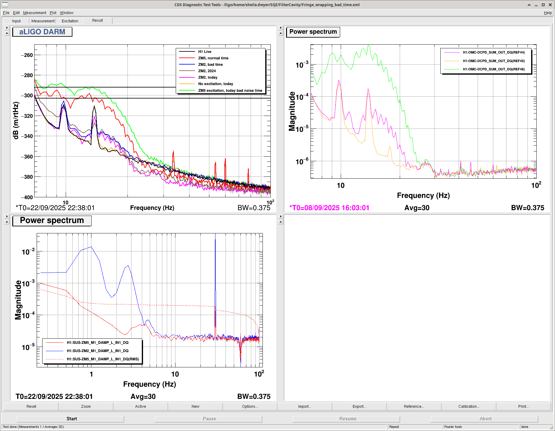
We repeated the fringe wrapping measurements, we saw a higher scattered amplitude when moving ZM5 than last week. (shelf is higher by 10dB). the ZM2 shelf is about the same. plot
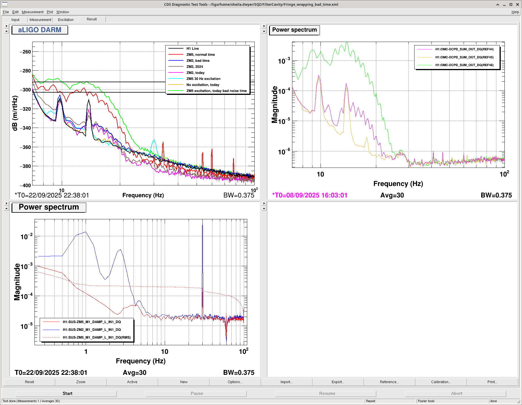
We also did some 30 Hz excitations in ZM5 + ZM2, we can see a bilinear coupling of these but the background didn't change during this excitation. plot
Derek and Elenna looked at the glitches in DARM that showed up at the time of the noise. Derek ran some hveto runs for times with frequency dependent squeezing and frequecy independent squeezing, and saw that filter cavity length signals are a good witness when the filter cavity is locked, when the filter cavity is not locked the giltches stay but aren't witnessed by the FC error signal.
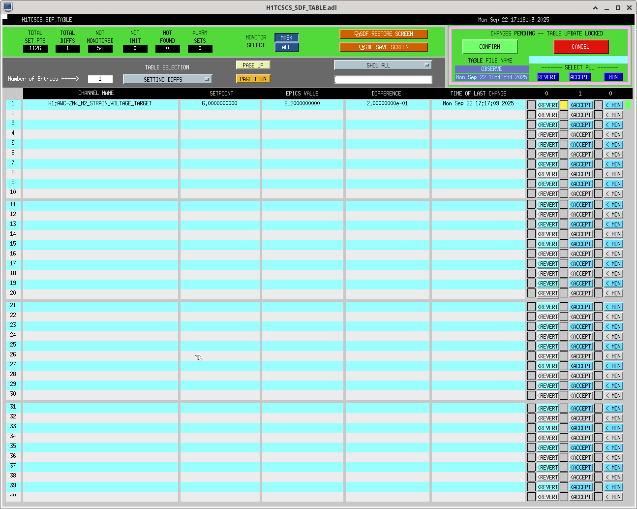
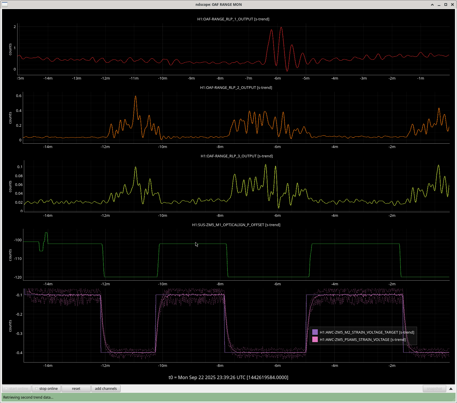
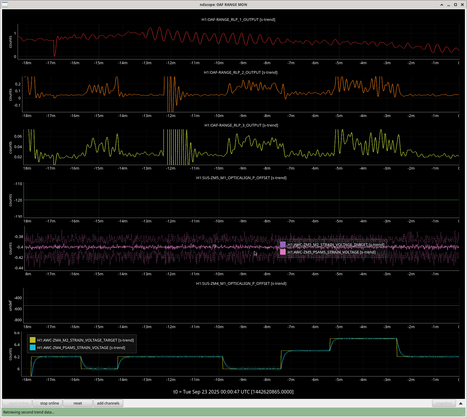
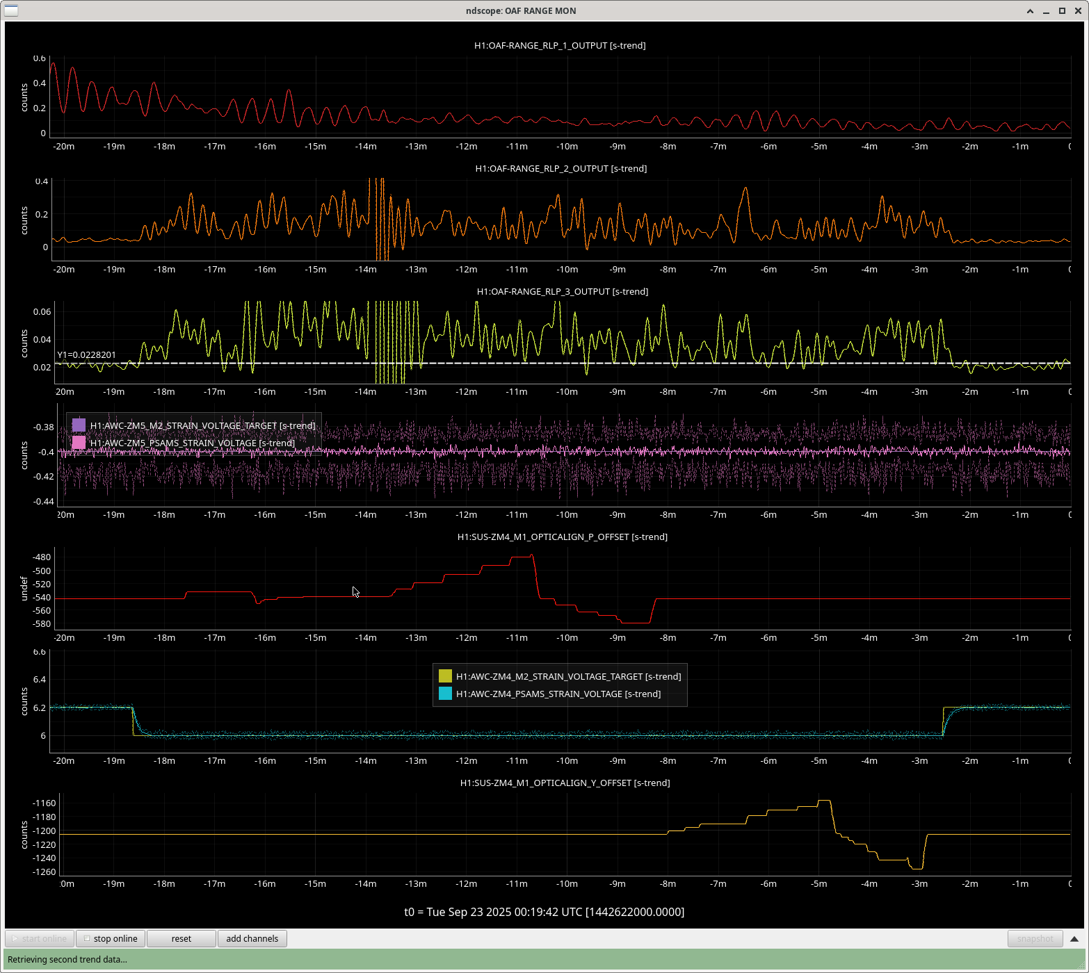
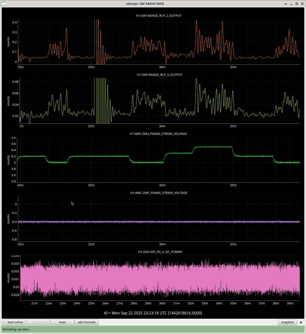
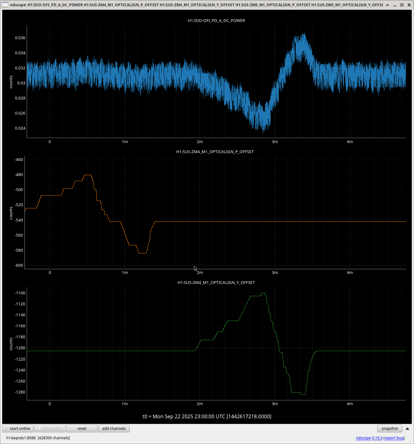
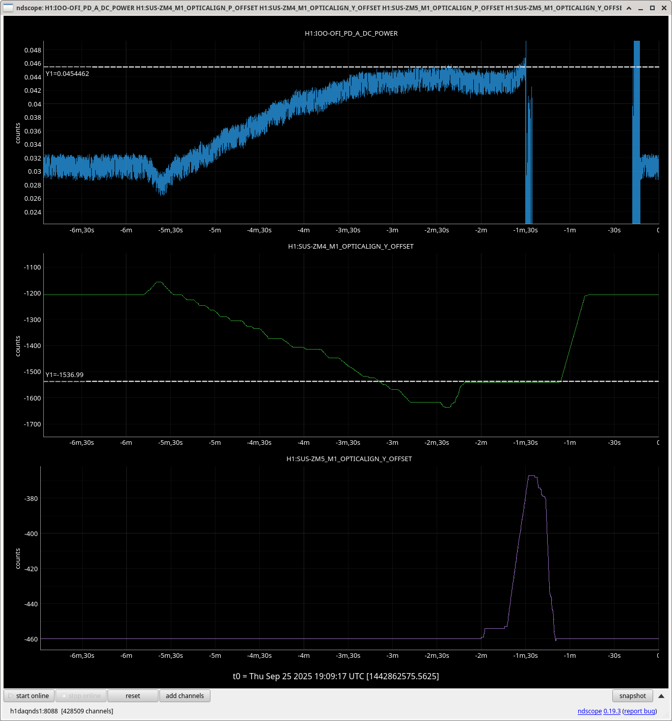
Camilla found that she could reproduceably make the noise go away by moving the ZM4 +5 PSAMs small amounts. She moved the PSAMs and adjusted the alignment to get a good level of high frequency squeezing back. She also tried to do this with alignment only.


h1sush7 and h1seih7 are back in operation.
During the rack work we lost h1sush7's second IO Chassis Adnaco, it should show 3 ADCs but lspci was giving nonsensical mappings. We power cycled both computer and IO Chassis for h1sush7 and it came back with no problems.
h1seih7 was un-fenced from Dolphin, no model restarts were needed.
HAM7 SWWD was reset to take it out of bypass.