TITLE: 10/14 Eve Shift: 2330-0500 UTC (1630-2200 PST), all times posted in UTC
STATE of H1: Observing at 151Mpc
INCOMING OPERATOR: TJ
SHIFT SUMMARY:
IFO is in NLN and OBSERVING (~10 hr lock)
2:53 - SQZ Dropped
4:10 - SQZ recovered, back to OBS
Mostly quiet shift except for the SQZ dropping due to FC lockloss.
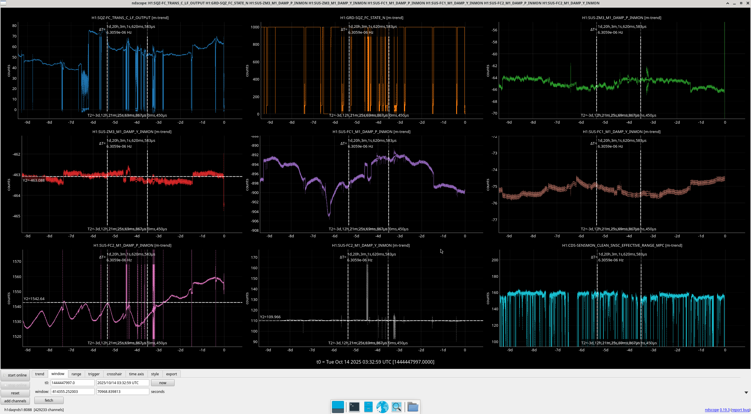
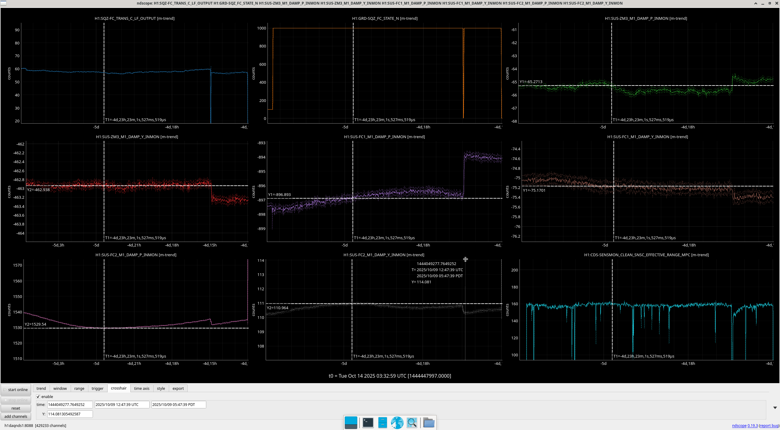
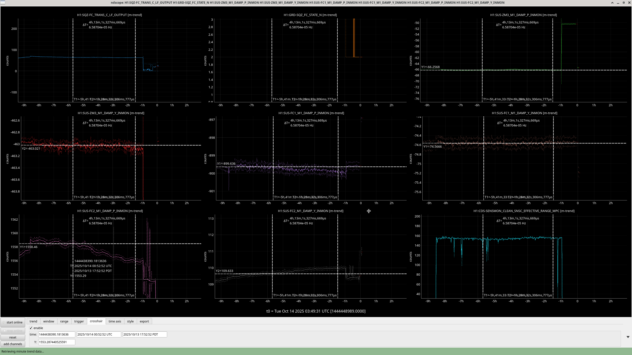
The Squeezer FC lost lock due to FC2 alignment walking away from a lockable GR_LOCKED configuration. As per the wiki, I trended the last time we had a stable lock and reset values for FC1, FC2 and ZM3 (P/Y). Then, I tuned FC2 a bit more to maximize GR_TRANS output. This worked.
Interestingly, I first tried an alignment from a few days ago but this didn't work. I did this because FC2 has been increasing quite a bit in the last few days (screenshots) - probably worth looking into. The values I set FC suspensions to (using opticalign sliders)
FC2 P: 1558, FC2 Y: 109.6
FC1 P: -899.6, FC1 Y: -74
ZM3 P: -66.25 ZM3 Y: -463
I hope this issue doesn't happen again during OWL shift though the trend below from a few days ago shows FC2 P going up for the last few days seemingly with SQZ compensating in its alignment. Anecdotally, it seems related to the temperature since there's a diurnal breathing day to day (lows at night, highs in the day). Tagging SQZ to look at FC2 and FC.
LOG: