Cheryl (over phone), Rahul
This morning we made changes to the damping filter for ITMX mode 2,3,4. We narrowed down the band pass filter and moved them away from Interfering from each other. Next we loaded the coefficients and made the gains to be zero on lscparam (followed by svn commit). Jeff. B then attempted to lock the IFO and during this time I found a good gain settings for ITMX mode 3 (gain of -20) and was tinkering with IMTX mode 2 (with a very small gain of -0.1). We lost lock after some time hence I was not able to find a good value for mode 2.
During the second attempt of locking, the modes were rung up and we lost lock very quickly. Next I reverted all the damping filter settings (including lscparams) back to how it was this morning at 8am. In the third attempt I requested Jeff. B to hold on at PREP_ASC_FOR_FULL_IFO, while I was manually damping the rung-up modes. We stayed at this state for an hour or so, and the rung up modes were damping well. Hence I requested Ed (who took over form Jeff. B) to start moving up the ISC lock state - here we lost the lock once again.
In the fourth attempt, the violins looked fine and we are currently locked and Observing (at 0:14 UTC).
TITLE: 03/17 Eve Shift: 23:00-07:00 UTC (16:00-00:00 PST), all times posted in UTC
STATE of H1: Lock Acquisition
OUTGOING OPERATOR: Jeff
CURRENT ENVIRONMENT:
SEI_CONF state: WINDY
Wind: 8mph Gusts, 5mph 5min avg
Primary useism: 0.02 μm/s
Secondary useism: 0.13 μm/s
QUICK SUMMARY:
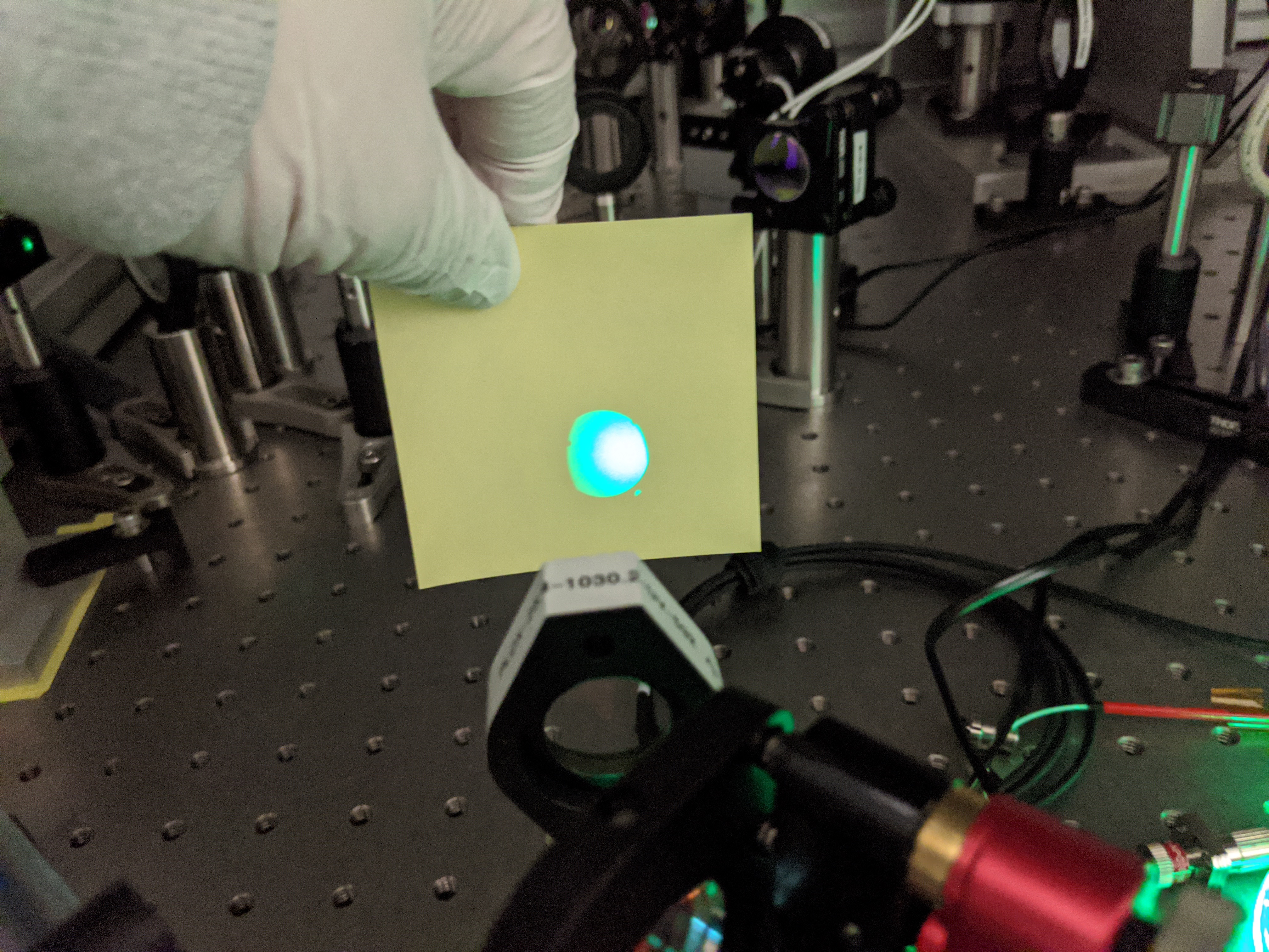
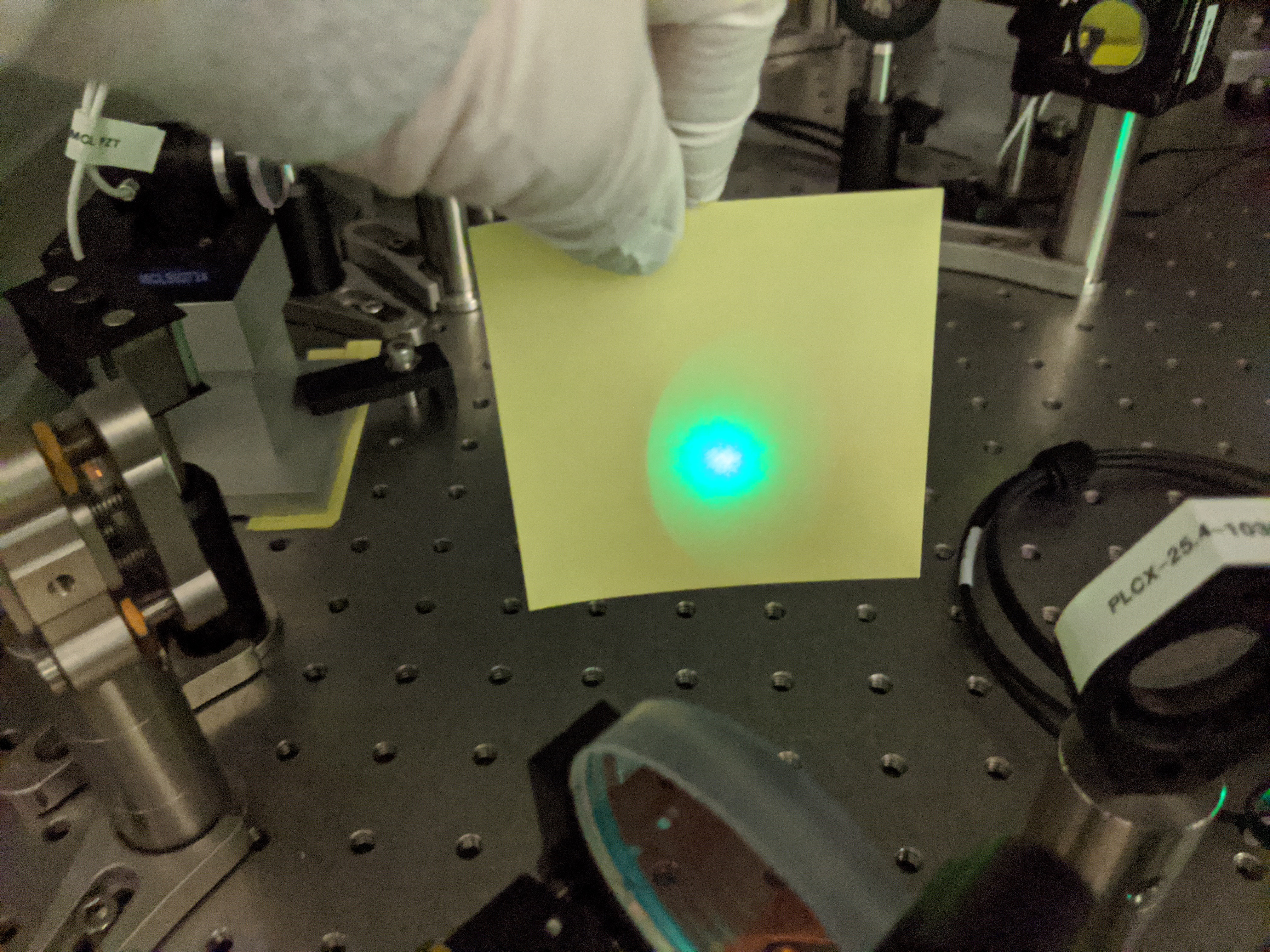
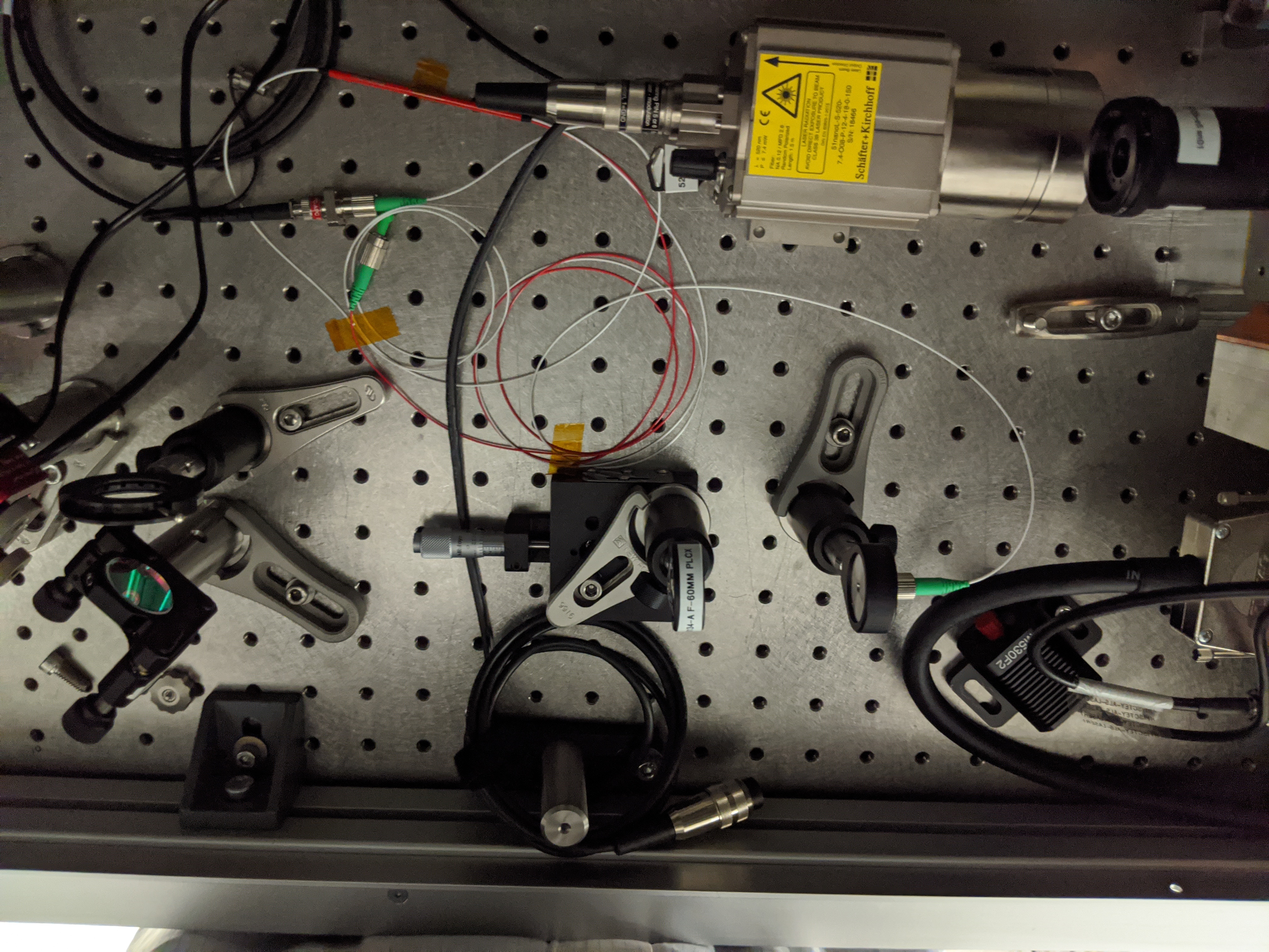
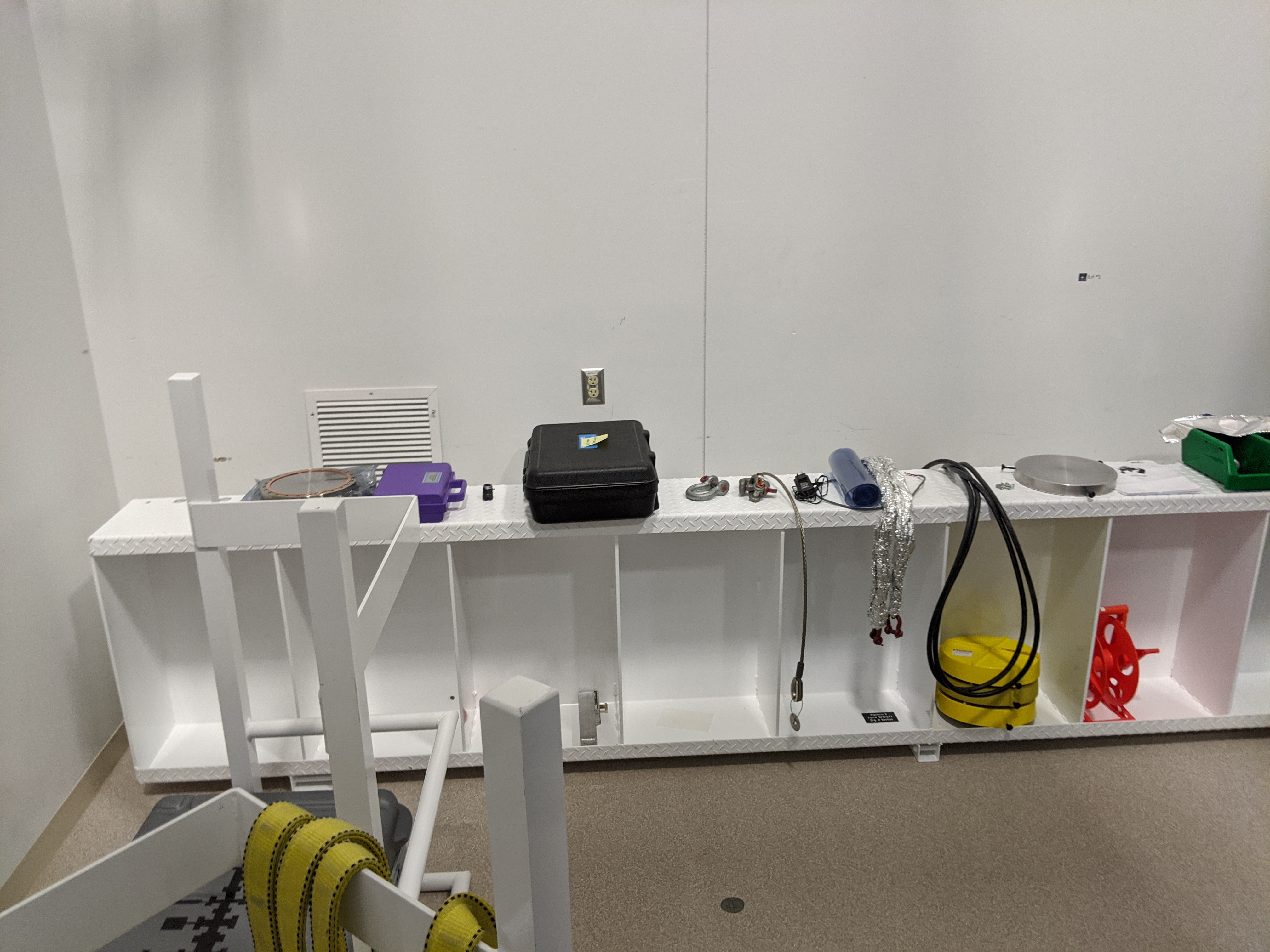
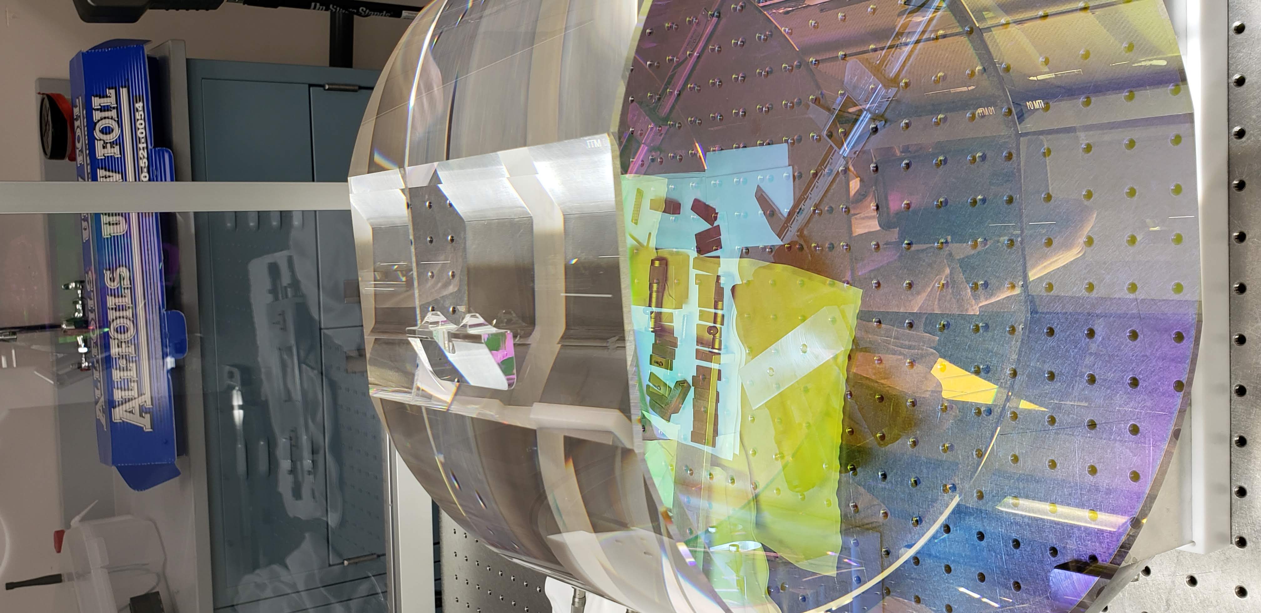
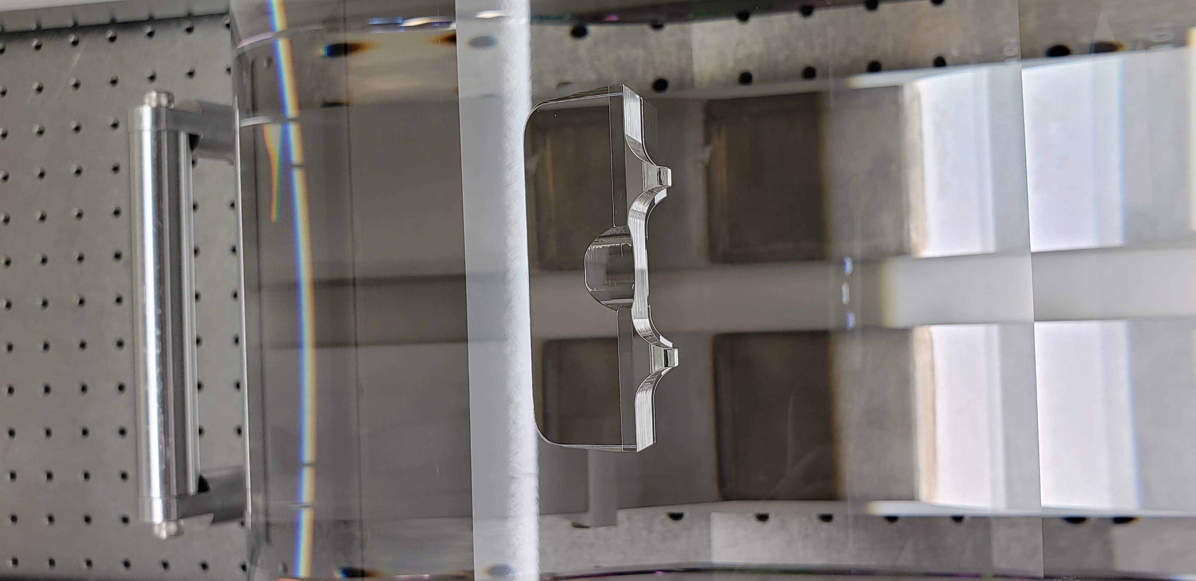
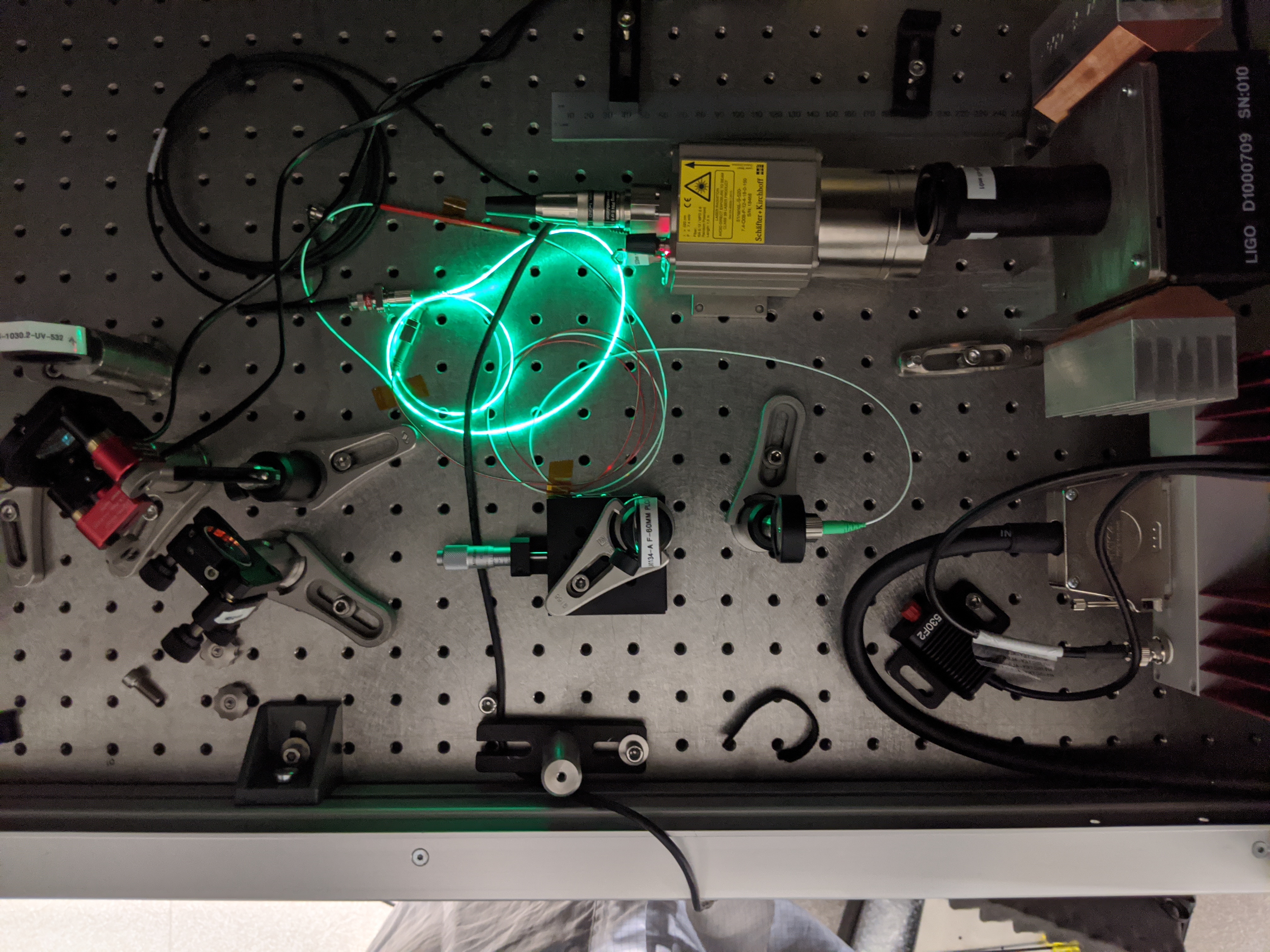
In preparation for HWSY investigations for Tuesdays and potential commissioning windows during O3 and post-O3, I did the following with remote help from TJ and Ed.
See D1400241 for table layout.
On Tuesdays or in dedicated commissioning windows, one has to transition EY to laser hazard before opening ISCTEY to operate HWSY laser.
The HWSY laser power supply needs to be removed from ISCTEY and disconnected from the mains before we can go back into observation.
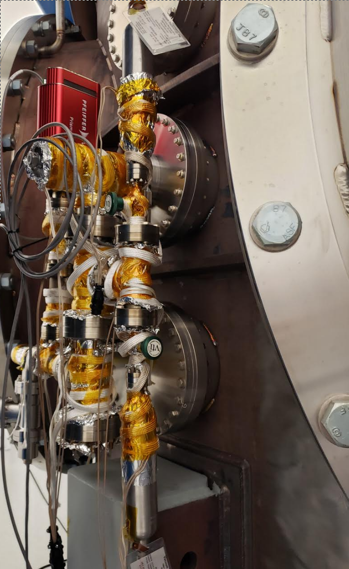
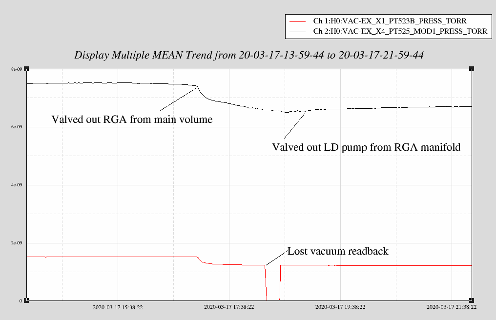
Isolated EX RGA that is bolted to BSC5 empty chamber and observed the main volume pressure immediately decrease. I was monitoring PT-510; starting pressure was 1.97x10^-9 Torr and fell to 1.68x10^-9 Torr several minutes later. Then we mysteriously lost EX vacuum channels and could not read out several pressure gauges including PT-510 (see Gerardo's aLOG 55654). A trend of PT-523 on other side of CP8 is attached, along with the hot cathode wide-range PT-525 gauge on BSC5 (still waiting for PT-510 to recover).
I connected the leak checker to RGA pump port, removed foil/tape from each conflat joint, one-by-one, while spraying He. The highest signal read from a couple of flanges was 3x10^-9 Torr-L/s of He (background 1x10^-12 Torr-L/s). Next week I'd like to revisit this to pin point the leaky joint(s). We are expecting a much bigger leak in e-7 Torr-L/s range.
Kyle came by (while honoring social distancing) and cycled the N2 calibration bottle valve in case that was the cause of bigger leak. Next week I will valve RGA back into main volume to measure new pressure.
RGA is OFF and valved out of main volume. Leak detector is still connected, but valved out of RGA manifold.
PT-510 is finally back online. Pressure now reading 1.67x10^-9 Torr.
(1.97e-9 - 1.67e-9)Torr x 2500 l/s = 7.5e-7 Torr-L/s (actual leak rate less because N2 pump rate lower than 2500 l/s)
This would have entailed taping the existing annulus thru holes on the old HAM4 septum plates that are bagged and stored on a pallet in the LVEA. This work was postponed as the taps need to be Class-B cleaned.
The past few nights Corey has been notified that ALS_DIFF was unable to find IR. Looking back at the logs this node would only pass through the state "NO_IR_FOUND", and not stop. This is because it would return true regardless of the values that got it to this point and move onto IR_FOUND. In ISC_LOCK, the CHECK_IR state has a different test than what was done in ALS_DIFF. So there is an inconsistency of what is acceptable for the amount of IR light in DIFF.
By this time the IFO was on its way up after maintenance, so I just made two quick changes:
The long term solution will be to make the tests the same, and hopefully find a way to have it be more reliable. I'll to talk to others and see what we come up with.
Given the request for a lighter maintenance period, the only work I performed on HAM 8 was sealing the remaining SUS bellows for contamination mitigation and mounting the lifting crossbeams. I spent the remainder of the maint period finalizing the machining modifications to the SEI transport tooling (details on this work to come in a future aLog). Tyler G
[Robert, Jenne]
This morning we locked DRMI and moved various optics around while Robert took video to see if the beam on the HAM5 side of the septum moves at all. Robert reported as we were working that he didn't see any obvious movement of that beam, but I'm sure he'll have more details after he's had a chance to review the movies.
We moved SR3 by 28 urad, we moved PR3 by several urad, we moved both ITMs by a few urad each, and I put an offset of 0.7 in the DC3 loop to move OM1 just in case the beam was somehow coming back through that septum viewport. We also put 1.4 Hz excitations into each of the 3 dofs of the OFI to make it move rail-to-rail on its (weak) actuators. Last week we had moved the OFI to the edge of its range in yaw, and had also moved ZM2 to the edge of its range, as well as put offsets into the AS_C SRC loop. So far, nothing seems to move the beam.
Robert will have more details later, but the beam is quite weak when we have the PRMI locked, even if I bring the power up to 20W injected. But as soon as the SRM comes into alignment, the beam shows up clearly with DRMI flashes. (The fast shutter was closed when we did that test last week).
The work this week and last Tuesday was all done DRMI-only, with the ETMs misaligned, and DRMI ASC on. I am running low on ideas of where this beam could be coming from, if I can't move it even the slightest bit with these optic moves.
The spot on the septum is not a beam. I think it's just an image (a reflection) of ZM2. I am guessing the septum plate has a machine finish - not very rough and directional. So the image is hazy and stretched vertically.
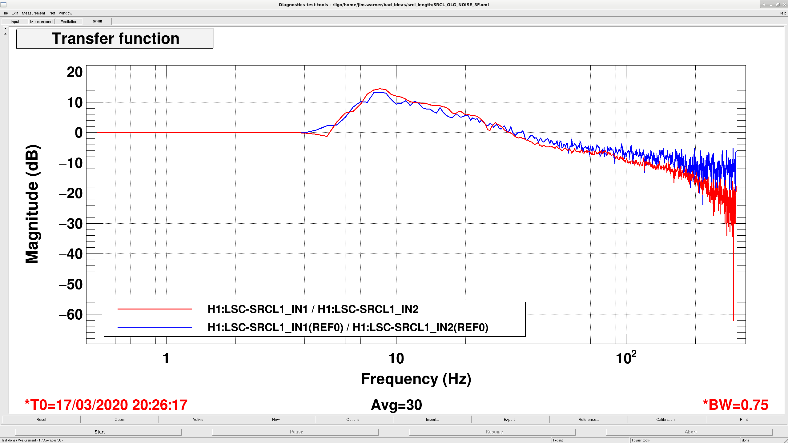
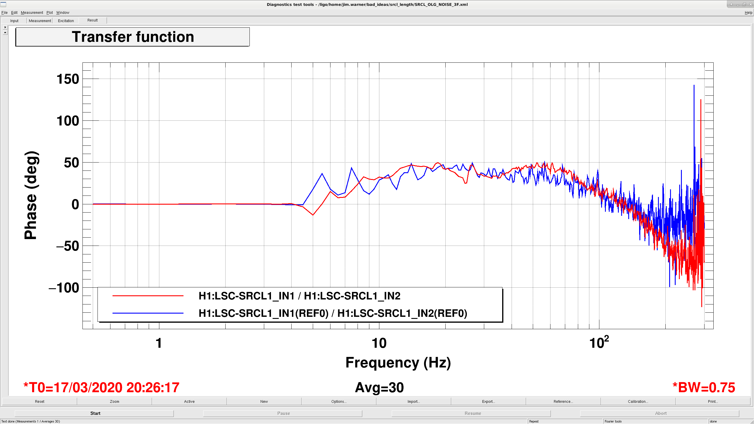
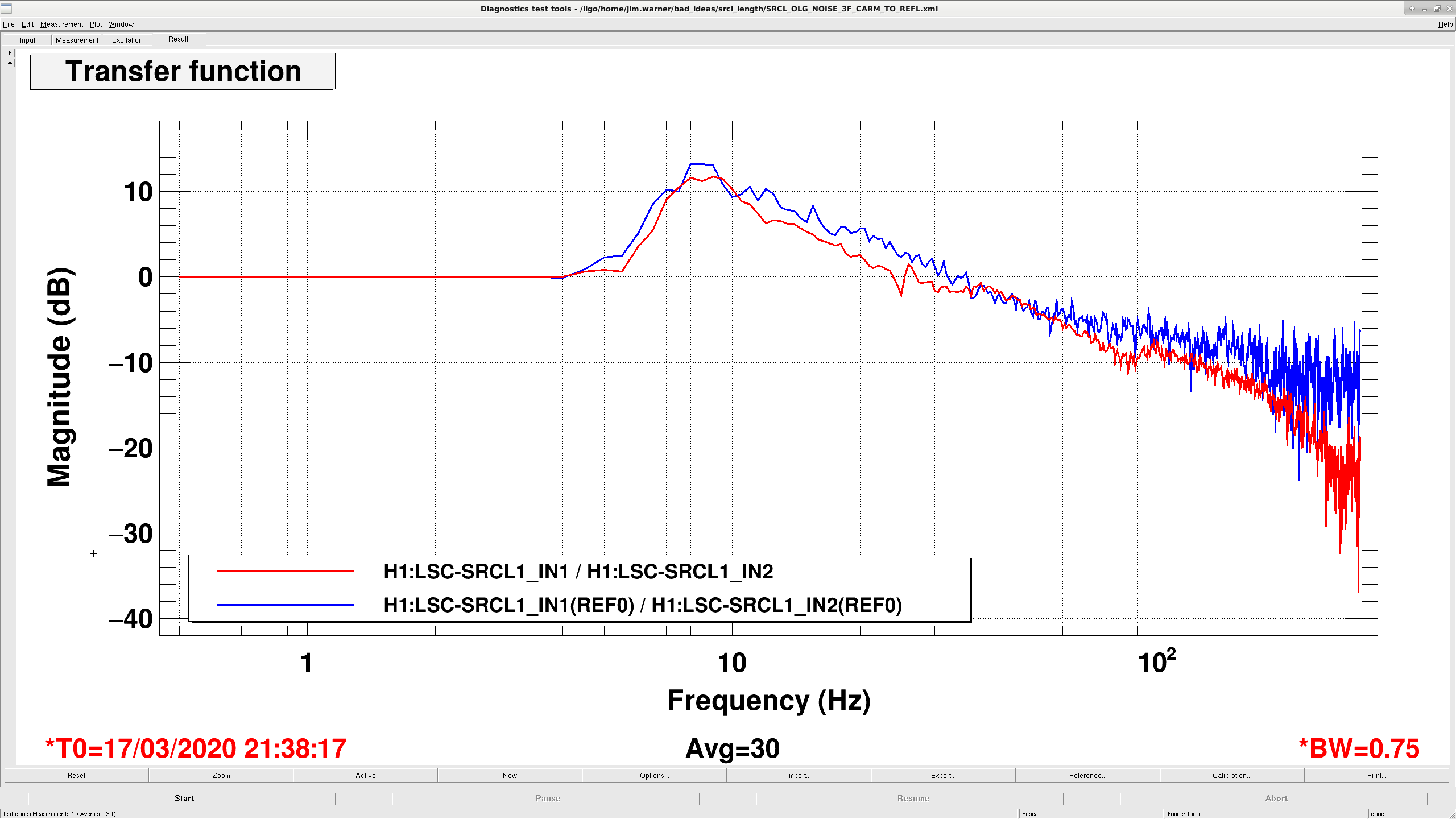
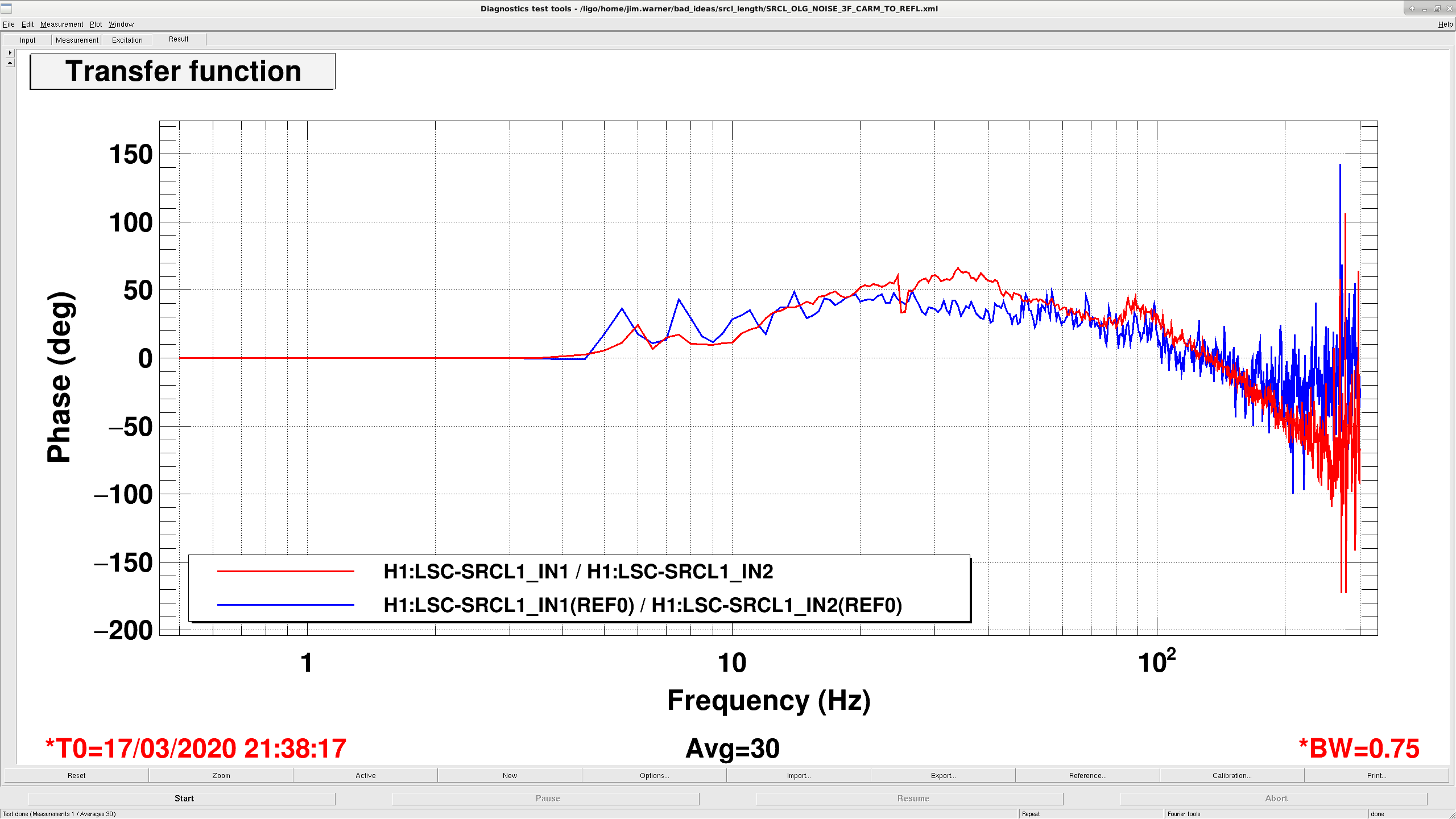
Following the discovery here, I tried to measure the SRCL OLG at Resonance today. After a couple tries, I was able to get a reasonable measuremet, but didn't find anything obviously off with SRCL at Resonance. Attached plots show the data from the measurement, the first plot is the amplitude and second is the phase, blue traces are a reference from a previous measurement, red is the current measurement. I was hoping to see that the gain or phase margin were close, but the gain margin at 80 hz is about 25 deg and the gain is something like -6 dB. There is a little bit of a bump at 80hz, but I wouldn't guess that that is a problem, given the phase margin.
Two other points, the previous alog pointed to the wrong DTT template, I used the SRCL_OLG_NOISE_3F.xml. And, I also was able to drive harder for this measurement,and had to, it was hard to resolve anything at 80 hz with the excitation in the measurement. The template is set with an amplitude of 30, I drove with an amplitude of 70.
Because we didn't find anything problematic here, Sheila suggested we try measuring at CARM_TO_REFL, and we just happened to have a lockloss. I'll try again in a bit.
Was able to get the CARM to REFL measurement. No screamingly obvious problem here either. Again, the first plot is the amplitude and second is the phase, blue traces are a reference from a previous measurement, red is the current measurement. There is a bit of phase loss around 80 hz, and a bit of a gain bump up to 90 hz, maybe that's enough to occasional swing unstable between CARM to REFL and resonance.
(Patrick T, Dave B, Richard M, Jeff B, Gerardo M)
It appears as if the h0vacex was restarted or powered off, which caused a bunch of alarms, Jeff B acknowledged a hadfull of the alarms.
It was not clear what happened, but CP8 fill control medm screen fields were all zero, and the liquid level control valve setting set to manual with a 0% open, both are a sign of a restart/reboot. Also the power for each individual cold cathode was OFF, they were turned back ON.
A burtrestore was done for h0vacex to today at 11:00. Instrument air alarms were done manually, LOW and HIGH were set to match other instrument air alarm settings via probe.
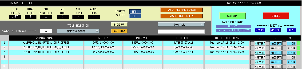
Accepted the three SDF DIFFs listed in the attached screen shot. Back in Observing
The electromagnetic actuator's bobbin coil has nearly 600feet of wire wound in 22 layers and 440 loops. Each layer of the wire must be bonded to the lower layer to prevent movement which would lead to wear and performance degradation. The bonding is done with a potting compound, N-Methyl -2-pyrrolidone for which Caltech's DeSalvo established a curing program set forth in T080148. This log is to validate the curing oven's performance with an eye on avoiding over-temperature as the bobbin wire's maximum operating temperature is in the neighborhood of the curing temperature; and, to be sure the oven programming is understood and correct yielding assembly efficiencies.
1) McCarthy procured a simple k-type thermocouple and 18 hour USB recorder, I like simple.
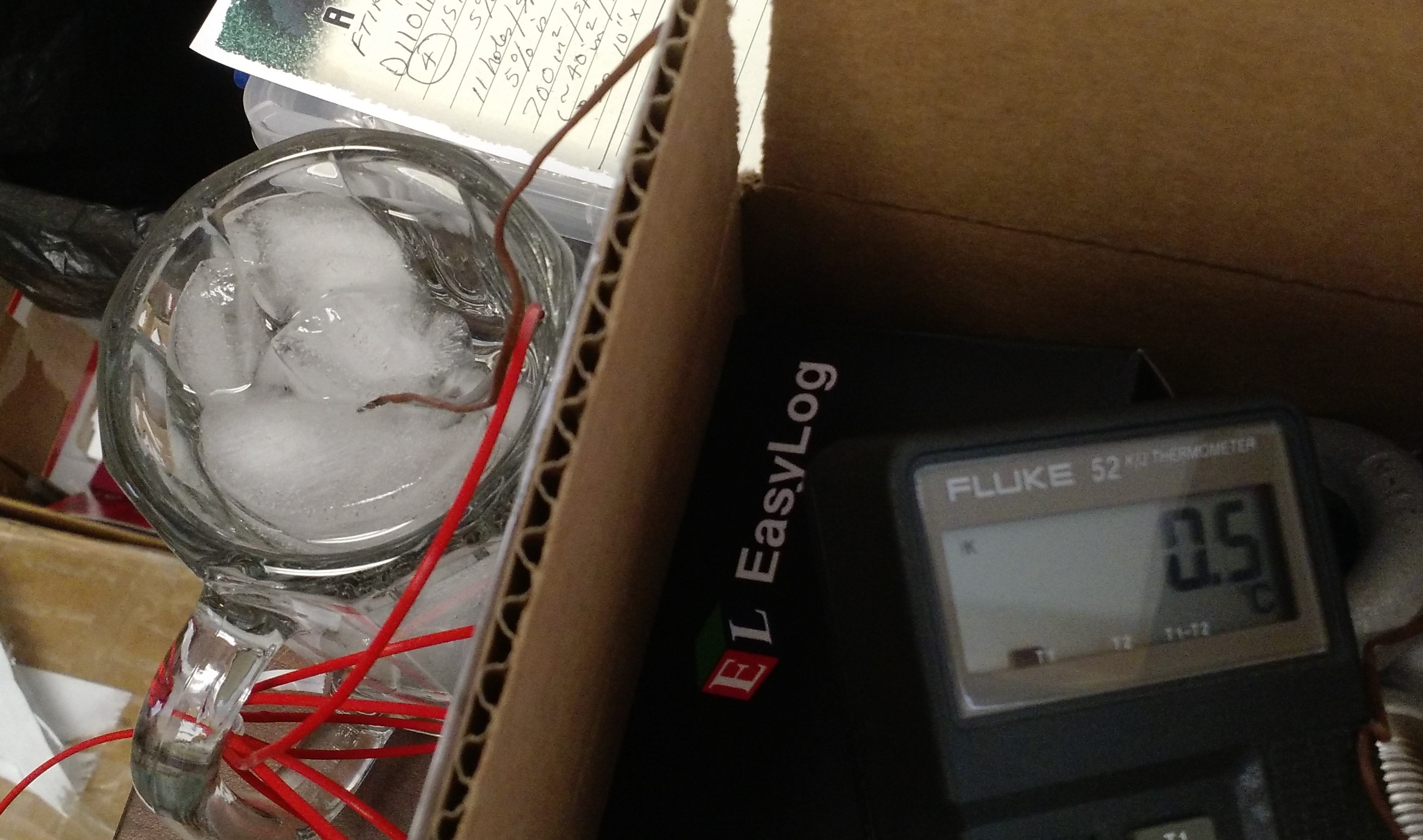
2) The thermocouple/recorder was checked against a Fluke meter in an ice bath.
3) The thermocouple was checked in a boiling water bath.
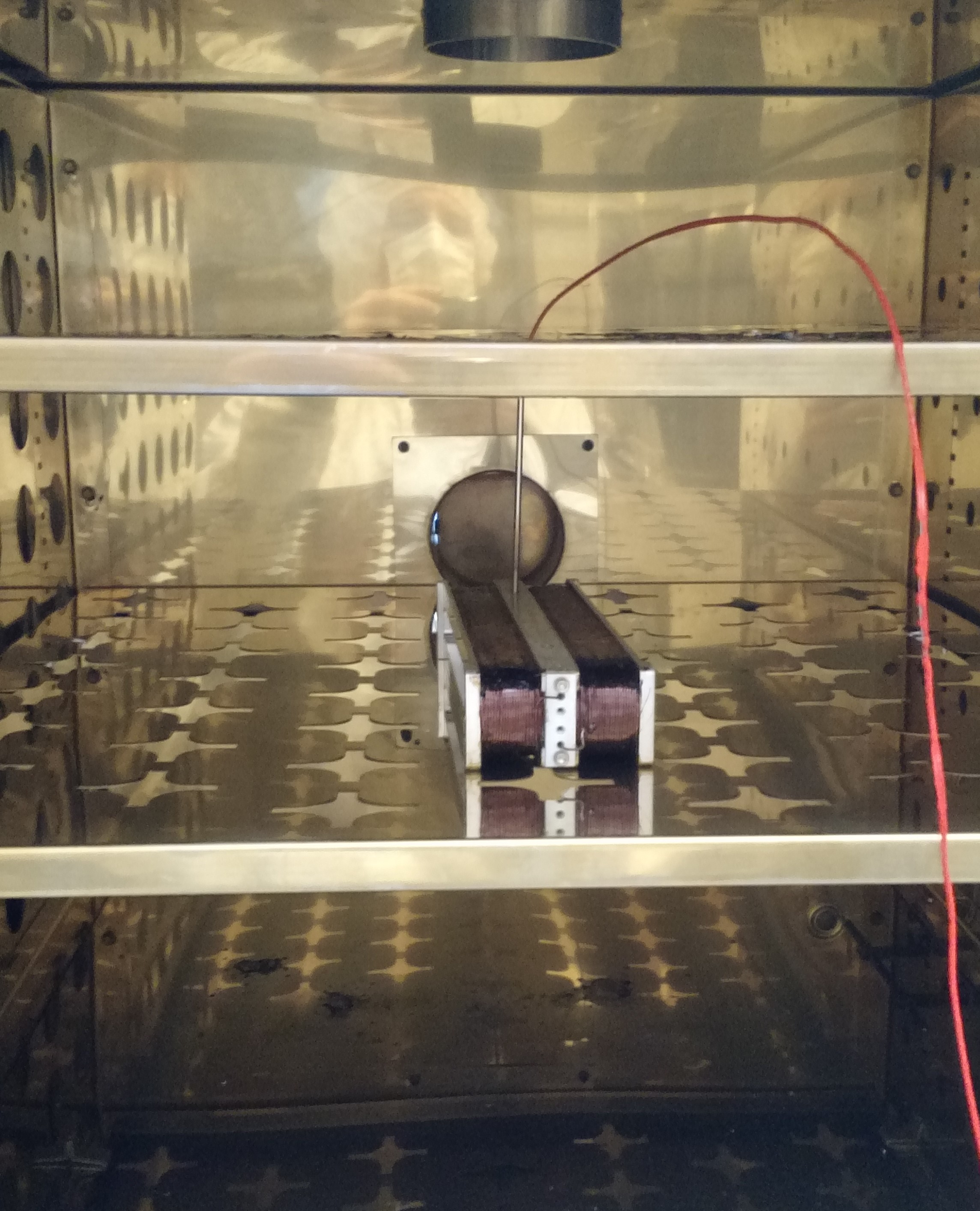
See the first image for a view of the iced mug and the fluke reading. The first pdf is the TC profile recorded in the ice bath followed by the boiling water bath.
In the ice bath, the TC recorded values of 0.5 to 0.0°C, just as the fluke meter was recording. In the boiling water bath, the TC recorded 99.0 & 99.5°C.
4) The thermocouple was run in the empty oven zero to max ASAP to look at that performance and set the available high-limit switch.
The second pdf shows the step to maximum temp as soon as possible profile. During the ~first 10 minutes, the oven temp increases at about 7C°/minute. During the ~last 10 minutes of heating, the oven temperature was climbing at just 1.6C°/minute. The maximum reading on the TC suspended in the air of the oven was 296.5°C. The oven thermometer was reading 300C. The temperature over limit was set while sitting at 300°.
5) The curing program was run with an existing wound bobbin and thermocouple.
The second image attachment shows the interior of the oven with the wound bobbin on the second shelf and the TC probe coming from above to rest in a screw hole on the bobbin. The final pdf shows the TC recording while the oven runs the profile prescribed in T080148.
The temperature recorded during the profile run shows a few things:
1) Even though the first soak period of 40 minutes was programmed to not start counting until the oven reached 200°C, the TC/bobbin was only at 192C when the countdown started. If critical, maybe this soak should go for 50 or 60 minutes. 2) As we already knew, at the higher temperature, the oven/part was unable to heat at the programmed 4C°/minute but only 2.2C°/minute. 3) This slower heat up during the second ramp allowed the part/TC to heat as well leading to a more preferred full 40minute soak at temperature. 4) The PID control of the oven and maybe it's lack of umph indicates there is little risk of temperature overshoot.
I was given 2 hours to continue with the removal of components from GV3, today the long manifold pipe was removed, the crane was used to lower and set the pipe on the ground. Still to remove: Ion pump assembly and a few small pipes.
Relocking after end of the maintenance window. Had a problem with ALS-X, which broke lock while trying to acquire. Found End-X ESD driver was off, due to glitch caused by vacuum folks while they were leak checking. Filiberto reset the driver and locking is proceeding.
To help speed up finding phone numbers, I've included a Roster link from the CDS Web Page.
I have added a new subclass to the guardian alerts for supernova alerts. The system was restarted at 11:03 and burt restore to 10:10 PDT.
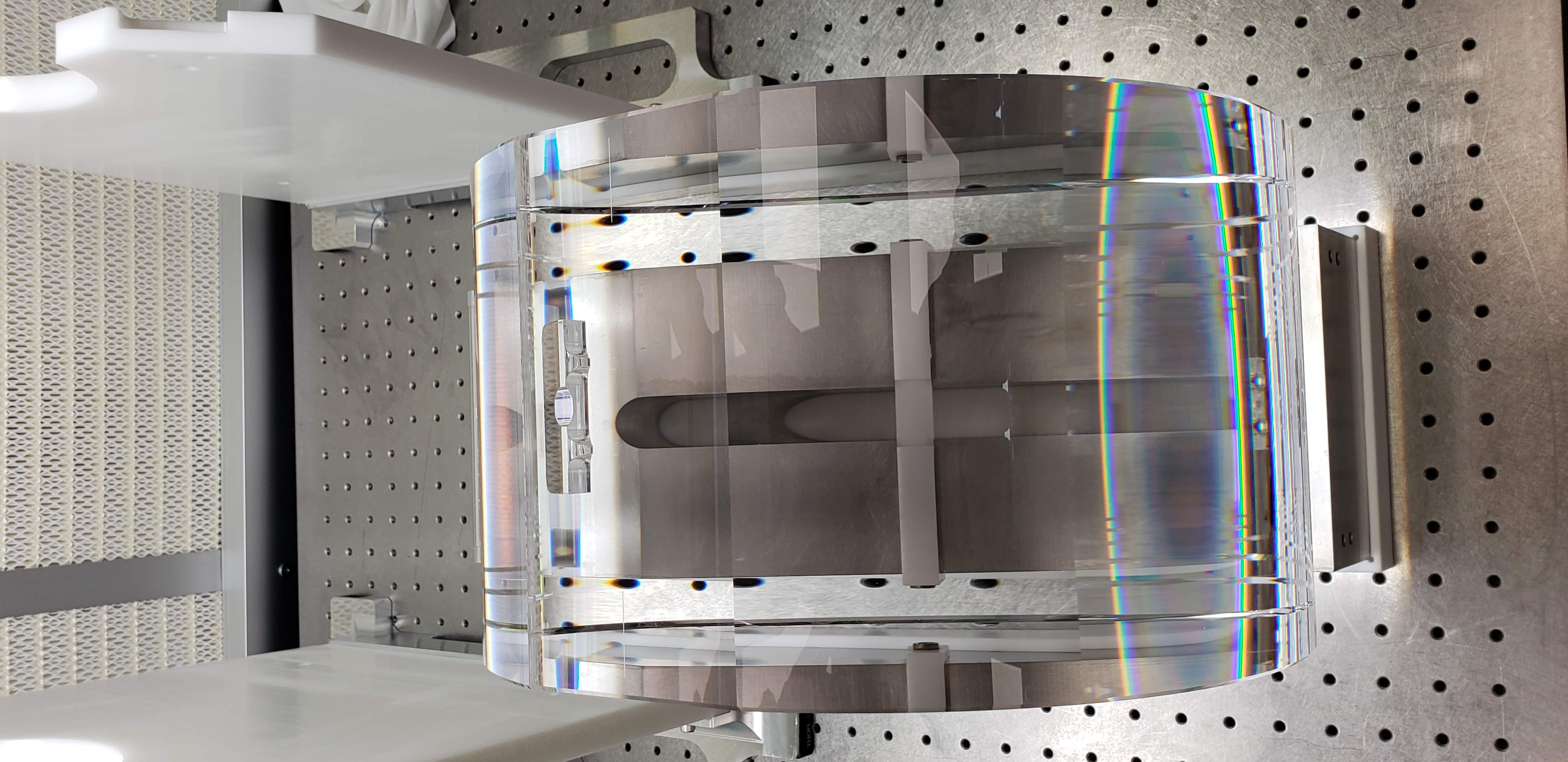
Gerardo and I, with Rahul in training, bonded PUM ear S1201472 to the test mass ITM01 S3 flat. (Yes, a PUM ear on a test mass - this was deemed acceptable in times of short test mass ear supply.) The bonding was straight forward and placed with 0.04mm measured error along the beam path axis (0.1mm is the tolerance).
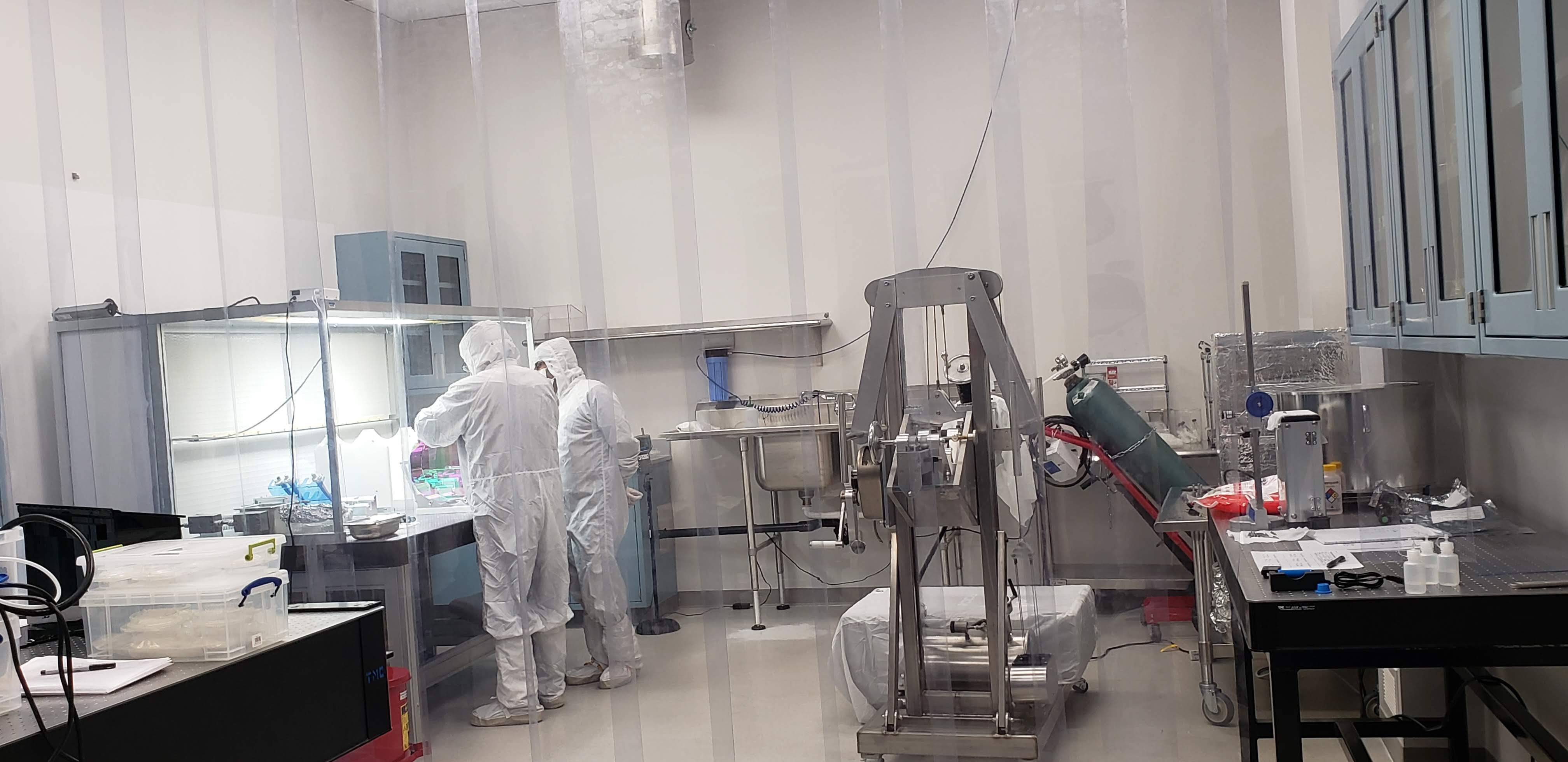
Note this was the first bond in the new lab space. All systems up and working well, thanks to Bubba/Tyler/Chris and the many hours Travis spent to help move everything.
The second ear bonding session is scheduled for next week.
Late entry - ITM01 had the second ear bonded on March 4th, 2020.
A PUM ear was again used. Ear - S1201484
During the bond, there was initially a set of bubbles which we watched migrate out over the course of a few hours. At 2 hours the location and bubble situation (very minimal) were well within tolerance.
The optic will be FirstContact cleaned and stowed in the coming week.
Plots of the three attempts at reaching NLN that did not make it, which include the ITMX violin modes 2, 3, 4, 5, 6, and 7. New filters were tested on modes 2, 3, and 4. One unexpected event was that damping mode 4 caused mode 5 output to increase, suggesting modes 4 and 5 are the same fiber. A couple of the lockloss events resulted in ITMX L2 DAMP pitch changing bu about 10urad, which doesn't seem to be the case for every lockloss, however the third lockloss can be attributed to violins, since some were rung up to a level where the RMS was 6.5 to 7.
Plot showing ITMX mode 5 ringing up. This is about 60 seconds of data, showing damping on modes 2, 3, 5, and 7
Trends are color coded:
Phase plots of the old and new damping filter is attached below.
Given below are the phase information (old vs new) for the band pass filter designed for ITMX mode 2,3,4. I have also attached 3 figures which shows the bode plot from foton. One can compare the old and new filter design using these plots.
ITMX mode 2 (504.887 Hz)
Phase old: -412 (+360-412= -52 degrees)
Phase new: -619 (+360-619 = -259 degrees)
This filter has a Phase difference of -207 degrees, hence will require a sign change by 180 degrees.
ITMX mode 3 (504.719 Hz)
Phase old: -360 (+360-360 = 0 degrees)
Phase new: -719 (+360-719= -359 degrees)
This filter has a Phase difference of 1 degree, hence will not require any phase change.
ITMX mode 4 (504.852 Hz)
Phase old: -402 (+360-402= -42degrees)
Phase new: -818 (=360 – 818 = -458 degrees, i.e. -98degrees)
This filter has a Phase difference of -57 degrees, hence will require a sign change by -60 degrees.