Displaying reports 35421-35440 of 89220.Go to page Start 1768 1769 1770 1771 1772 1773 1774 1775 1776 End
Reports until 17:55, Tuesday 03 March 2020
H1 PSL (PSL)
corey.gray@LIGO.ORG - posted 17:55, Tuesday 03 March 2020 - last comment - 19:39, Tuesday 03 March 2020(55417)
H1 Status Post-8+hr Maintenance Day

Once activities ended for Maintenance Day, immediately went for an Initial Alignment.

One item to note for alignment, was there was a lockloss where the PSL's FSS went into an oscillating state.  Toggled the FSS Autolocker.  And then Turned Off the autolocker for ISS 1st Loop (per instructions in January).

Currently have made a few attempts at locking, and have not been able to lock DRMI (other than a short 2-sec one) so far (even with nice flashing).  Have had 1-2 more instances of the FSS going into oscillation and this need operator attention.  Going to give DRMI locking a few more attempts with PRMI locks as well.  After that, may try another alignment?

Definitely not rosy after Maintenance Day and something may be amiss.  Will post update later.
Comments related to this report
corey.gray@LIGO.ORG - 18:03, Tuesday 03 March 2020 (55418)

Additional NOTE: 

CHECK MICH FRINGES appears to not work in that it looks like it's trying to lock a bright fringe (or just having trouble locking on a dark fringe).  Either way, it is not clear how to adjust the BS when ISC LOCK is in the CHECK MICH FRINGES state.  (think this has been the case for 2-3 months?).

CORRECTION:  Looks like nowadays CHECK_MICH_FRINGES is an automated step (i.e. raises PSL power, dithers BS, then runs Mich Offloaded).  So, looks like there is no "manual CHECK_MICH_FRINGES" like what operators used to do a few months ago.

corey.gray@LIGO.ORG - 18:08, Tuesday 03 March 2020 (55419)CAL

More Notes:

  • GWIstat says H1 has "Calib Issue" (probably not related to locking, but wanted to note).
  • Winds are hovering around 12mph
corey.gray@LIGO.ORG - 18:11, Tuesday 03 March 2020 (55420)

BRSx continues to be in the DAMPING state post-EX noisy work in the VEA.  See attached "BRS Health" plots.

Addendum:  3:23 EX signals return to normal & it returns to READY state (& SEI_CONF node's NOMINAL box turns from orange to all green).

Images attached to this comment
corey.gray@LIGO.ORG - 18:14, Tuesday 03 March 2020 (55421)

On current lock, have had (4) attempts at DRMI with NO locks at all.  PRMI locks with no problem.  

Contemplating an alignment and then if that doesn't work again, will start calling for help.

corey.gray@LIGO.ORG - 19:39, Tuesday 03 March 2020 (55422)

Have been noticing in ISC_LOCK log that it says "Unstalling TCS_ITMY_CO2_PWR".

Going to the TCS_ITMY_CO2_PWR node shows it in a loop between "HOLD_POWER" & "ADJUSTING_POWER".  Not sure if this is normal, or not, but wanted to mention this oddity (because TCSx does not have this issue).

But this might be a normal/usual thing.  Just looking for anything unusual.

H1 ISC
marc.pirello@LIGO.ORG - posted 16:51, Tuesday 03 March 2020 (55414)
RF Noise Hunting

We performed some noise hunting at the PSL racks today, primariliy looking at the 9MHz and 45MHz RF Amplifier outputs.  Dick assembled a passive RF rectifier which we used to measure the power fluctuations at a low enough frequency to see on the scope.  We applied that signal to a LPF and then amplified it through an SR560 with 100x gain.  An adjustable attenuator was placed before the amplifier to incrementally attenuate the signal.

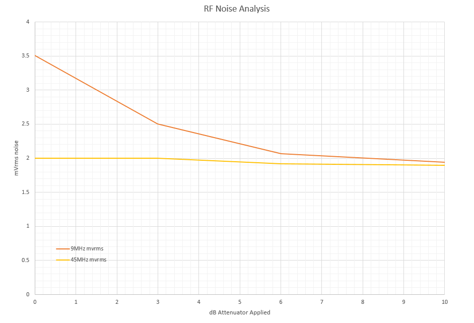
After some issues with grounding, his diode was conducting too much due to a 74mV DC difference between instrument ground and rack ground, we were able to acquire some data.  Attached is a plot of attenuator value applied vs mVrms noise measured.  We gather that the noise floor is around 2mVrms.  The 45MHz signal sits right on the noise floor, no amount of applied attenuation would push this signal down any lower.  The 9MHz was different, and as we applied attenuation, the mVrms noise decreased.  It was very subtle, but worth mentioning.


D. Gustafson, M. Pirello

Images attached to this report
LHO VE
chandra.romel@LIGO.ORG - posted 16:40, Tuesday 03 March 2020 - last comment - 17:20, Tuesday 03 March 2020(55412)
EX MTP turbo installed

{Kyle, Gerardo, Chandra}

After hard closing GV20, we removed the old main volume turbo and installed the new shiny turbo at EX. We were able to leak check the GV joint with a background of 4x10^-9 Torr-L/s of helium, with no detectable leak, but ran out of time to leak check the main volume to find the air leak.

Next maintenance period we will soft close GV20 and let the {wet} turbo pump for enough time to reach a pressure comparable to main volume in order to valve it in and leak check suspect joints, and allow leak detector background to fall below 1x10^-9 Torr-L/s.

We also need to finish properly anchoring the turbo stand. Ran into a galled bolt at top plate, and a few anchor bolts are mismatched enough with pre-drilled anchor inserts that we need to file down the anchor brackets.

Good work, team.


Comments related to this report
chandra.romel@LIGO.ORG - 16:41, Tuesday 03 March 2020 (55413)

Thanks to Tyler for helping crane away the old turbo stand. Equipment is sitting in loading/cleaning area and will be hauled away at next opportunity.

chandra.romel@LIGO.ORG - 16:50, Tuesday 03 March 2020 (55415)

Note that all other turbo joints were pre-assembled and leak checked by Kyle.

chandra.romel@LIGO.ORG - 17:20, Tuesday 03 March 2020 (55416)

We inspected GV19 and GV20 for spindle nuts, torque settings, and set screw status. I will record results in the google doc linked in DCC tomorrow (Q1800019).

H1 CDS
filiberto.clara@LIGO.ORG - posted 16:35, Tuesday 03 March 2020 (55411)
Fiber Rack Modifications in MSR

WP 8552

Removed old fiber patch panel in MSR fiber rack to make room for new MTP style panel that will be needed for the IO chassis upgrade.

LHO General
corey.gray@LIGO.ORG - posted 16:32, Tuesday 03 March 2020 (55406)
Transition to EVE Shift

TITLE: 03/03 Eve Shift: 00:00-08:00 UTC (16:00-00:00 PST), all times posted in UTC
STATE of H1: Preventive Maintenance
OUTGOING OPERATOR: TJ
CURRENT ENVIRONMENT:
    SEI_CONF state: SC_OFF_NOBRSXY
    Wind: 20mph Gusts, 16mph 5min avg
    Primary useism: 0.11 μm/s
    Secondary useism: 0.33 μm/s
QUICK SUMMARY:

Active Maintenance Day Work when I walked in:

After a few minutes, VAC team let us know they were cleaning up and ending work for the day.  Jenne finished up her work and immediately started with an alignment (X & Y arms were way off, but certainly handle-able).  Continuing with alignment!

H1 CDS (DetChar)
filiberto.clara@LIGO.ORG - posted 16:28, Tuesday 03 March 2020 (55409)
Power Configuration for EX Photodiode Amplifier Unit Changed

Evan G. reported some improvement in our noise lines from Feb 11-18 (alog 55352). Alog entries (alog 55041, alog 55160) show EX Baffle Photodiode Amplifier Chassis was powered down during this time.

Today the power configuration for the unit was changed. It was previously powered by ISC ±24V rack power. It is now being powered by a bench power supply. This change isolates the unit from the ISC field rack.

F. Clara, E. Goetz, R. McCarthy

LHO General
thomas.shaffer@LIGO.ORG - posted 16:25, Tuesday 03 March 2020 (55390)
Ops Day Shift Summary

TITLE: 03/04 Day Shift: 16:00-00:00 UTC (08:00-16:00 PST), all times posted in UTC
STATE of H1: Aligning
INCOMING OPERATOR: Corey
SHIFT SUMMARY: Extended maintenance day today, many successful activities. Corey has started aligning.
LOG:

H1 General
edmond.merilh@LIGO.ORG - posted 16:08, Tuesday 03 March 2020 (55408)
ZOTAC Workstation Computer Retrieved...

from EY and brought to Carlos.

H1 General
edmond.merilh@LIGO.ORG - posted 16:07, Tuesday 03 March 2020 (55407)
LVEA Sweep

LVEA is now good for Observing.

H1 CDS
richard.mccarthy@LIGO.ORG - posted 15:28, Tuesday 03 March 2020 (55404)
CDS Wireless Access Changed to new system

Today we removed the old Wireless Access Points in the Ends and Corner station and deployed the new ones that are controlled through the CDS Unify MEDM screen.  The 6 laptops that are in the computer user's room have all been updated and tested to function on the new wireless system.  Next step will be to replace the mid station units.

If you use the laptop please return it to the stand in the Computer user's room and plug it back in.

New laptops will also be deployed to the End stations to replace the current workstations.

H1 PSL (PSL)
keita.kawabe@LIGO.ORG - posted 14:50, Tuesday 03 March 2020 (55402)
Locking difficulty in FSS is due to oscillation

This morning we had a hard time relocking FSS.

I bypassed auto-locker's  gain ramping (auto-locker automatically ramps the input to H1:PSL-FSS_COMMON_GAIN_CALI filter from zero to H1:PSL-FSS_COMMON_GAIN after it thinks that the FSS is locked to the right mode for more than H1:PSL-FSS_AUTOLOCK_DELAY1) by disabling the input to H1:PSL-FSS_COMMON_GAIN_CALI, set the resonant threshold low so that the auto locker wouldn't restart scanning, and observed what's going on.

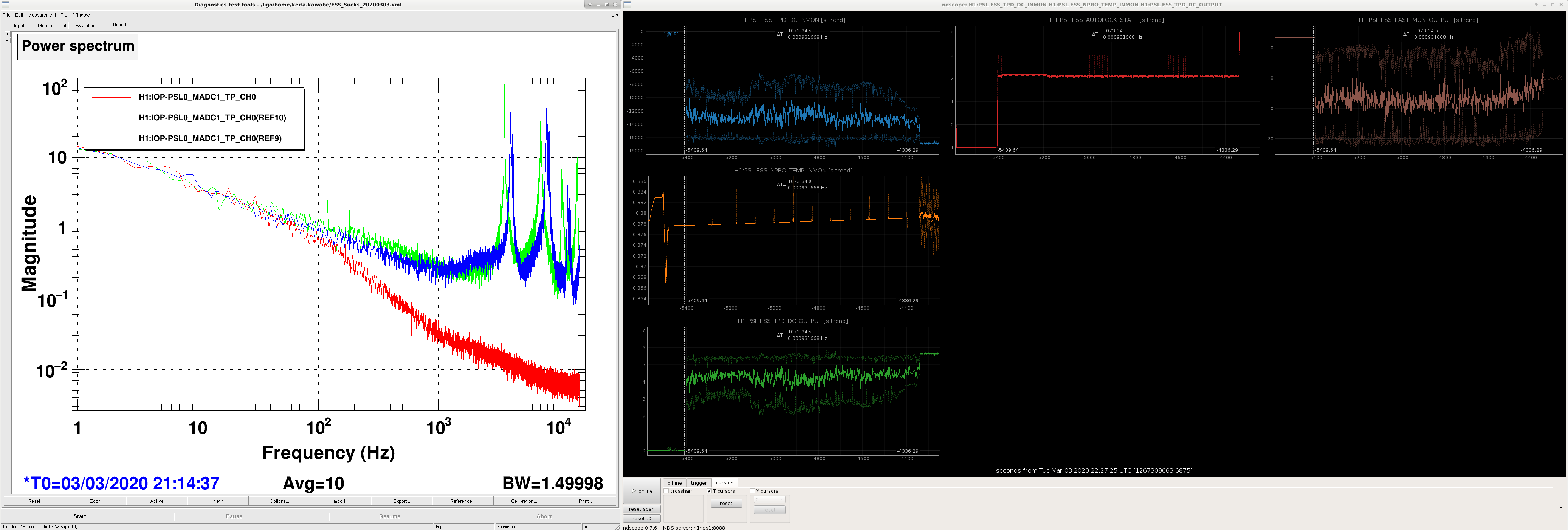
It seems like there was some oscillation going on, shown in green and blue in the attached left (these are the IOP channel for FSS_MIXER_IN1). I cannot tell if this was really as low as 3kHz or if this was just aliasing.

Oscillation didn't change much as I changed various things e.g. re-enabling the gain ramping with smaller common gain, larger and smaller fast gain and  different PMC locking gain.

After 10 minutes or so while left in oscillation while I was trying things, the error signal started decreasing, the peak went higher in frequency (blue trace in DTT is 2 minutes younger than gree), and after 19 minutes suddenly the oscillation is gone (red trace in dtt).

It's locked now, but it's probably worth going to the PSL room and see signals on the oscilloscope as well as the network analyzer when this is going on.

Images attached to this report
H1 CDS
david.barker@LIGO.ORG - posted 14:41, Tuesday 03 March 2020 (55401)
h1lsc0 front end timing error, all models restarted

Jonathan, TJ, Dave:

just before noon local h1lsc0 suffered a timing error, reported as ADC timeouts on all the user models. There was no disconnect between the computer and the IO Chassis, so we just needed to restart all the models to recover the system. Note: h1ioplsc0 is the timing master for the h1oaf1 computer. It appears that h1oaf1 rode through the restarts, but if we have any problems with this machine's models tonight we may need to consider restarting them.

The timing glitch is most probably related to ISC electronics work which was ongoing at the time.

H1 SQZ (ISC)
jenne.driggers@LIGO.ORG - posted 11:22, Tuesday 03 March 2020 - last comment - 14:38, Thursday 05 March 2020(55395)
Investigations of squeezer oscillations

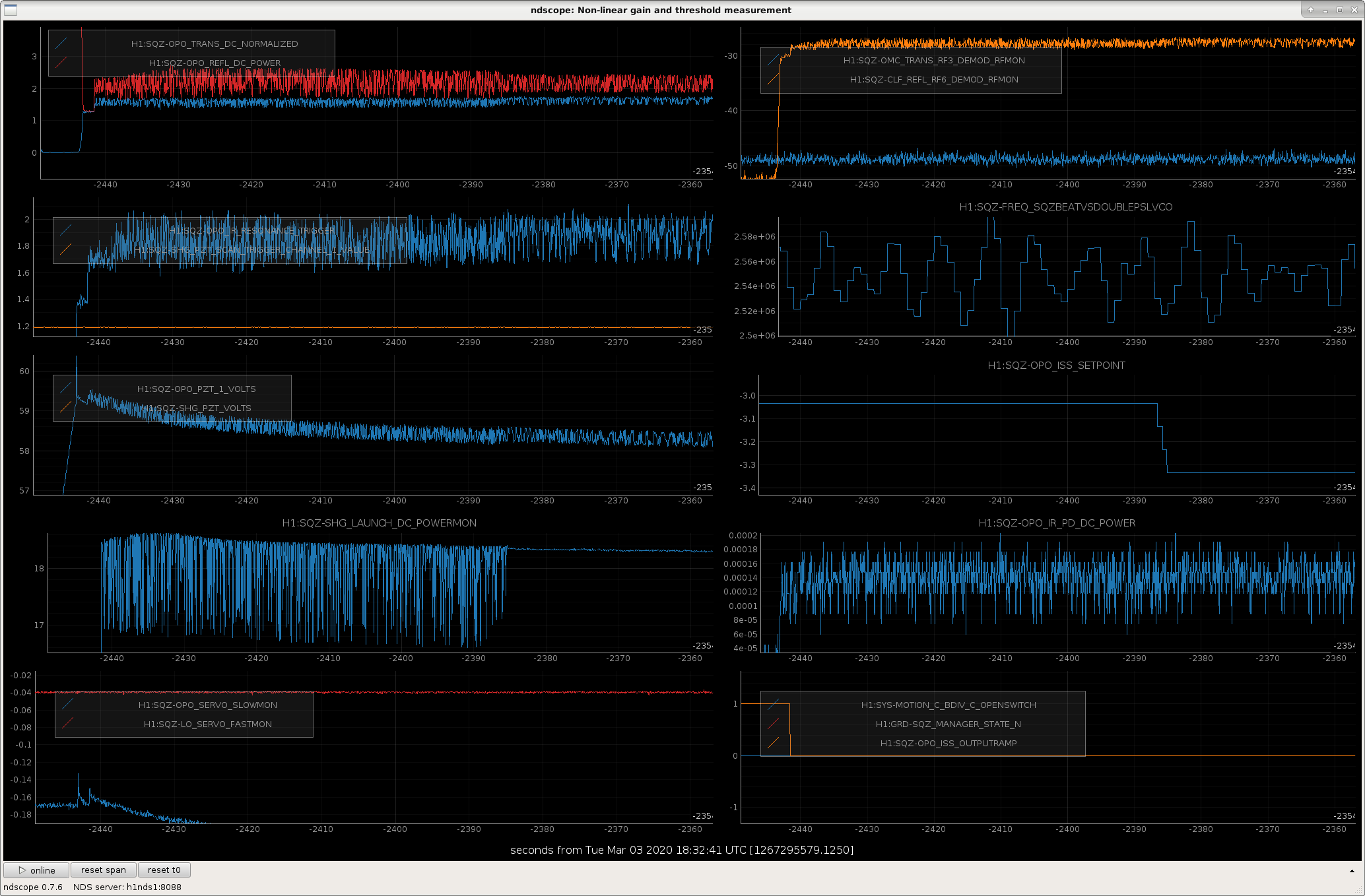
[Sheila, Jenne]

Although the squeezer seems to not have gone into oscillation since last Thursday when we lowered the green power (alog 55339), we are looking to see if we can better understand the cause and ameliorate it (spoiler alert: so far we don't know, although we have further tests to try today). 

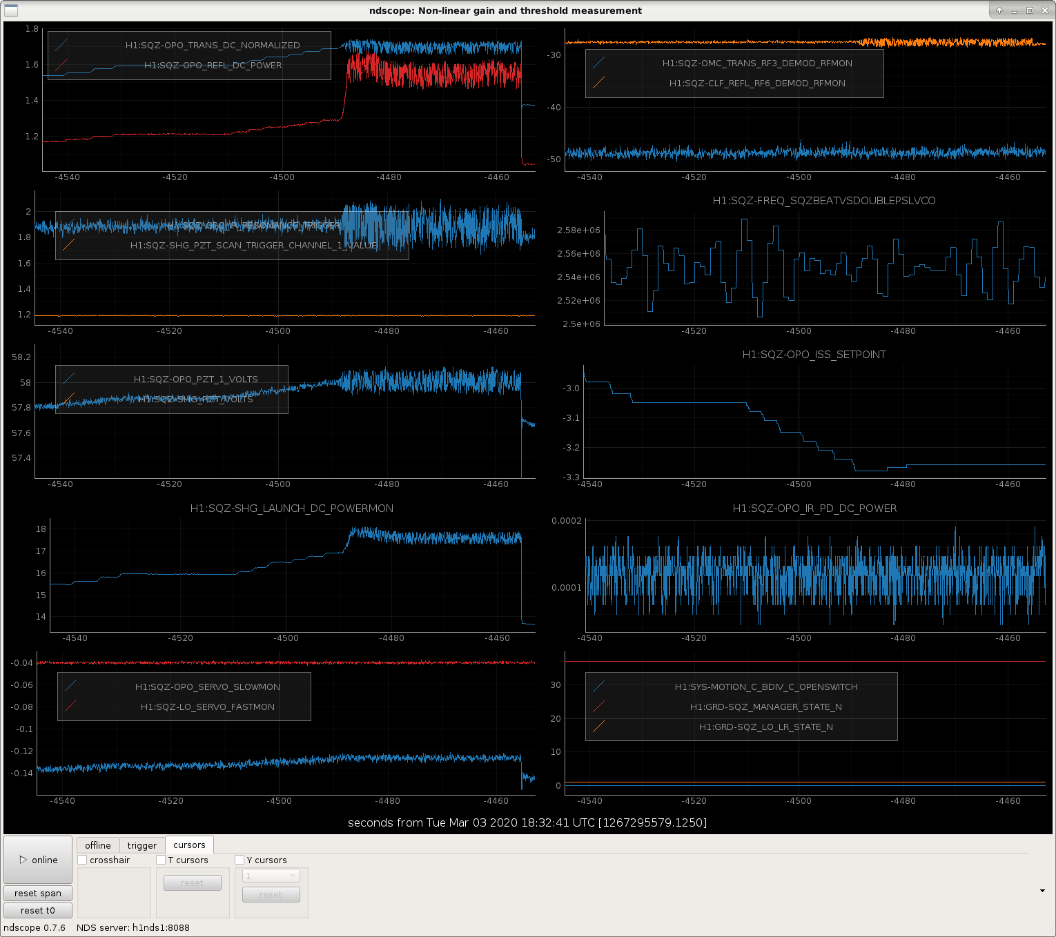
Here's what we've done so far:

Images attached to this report
Comments related to this report
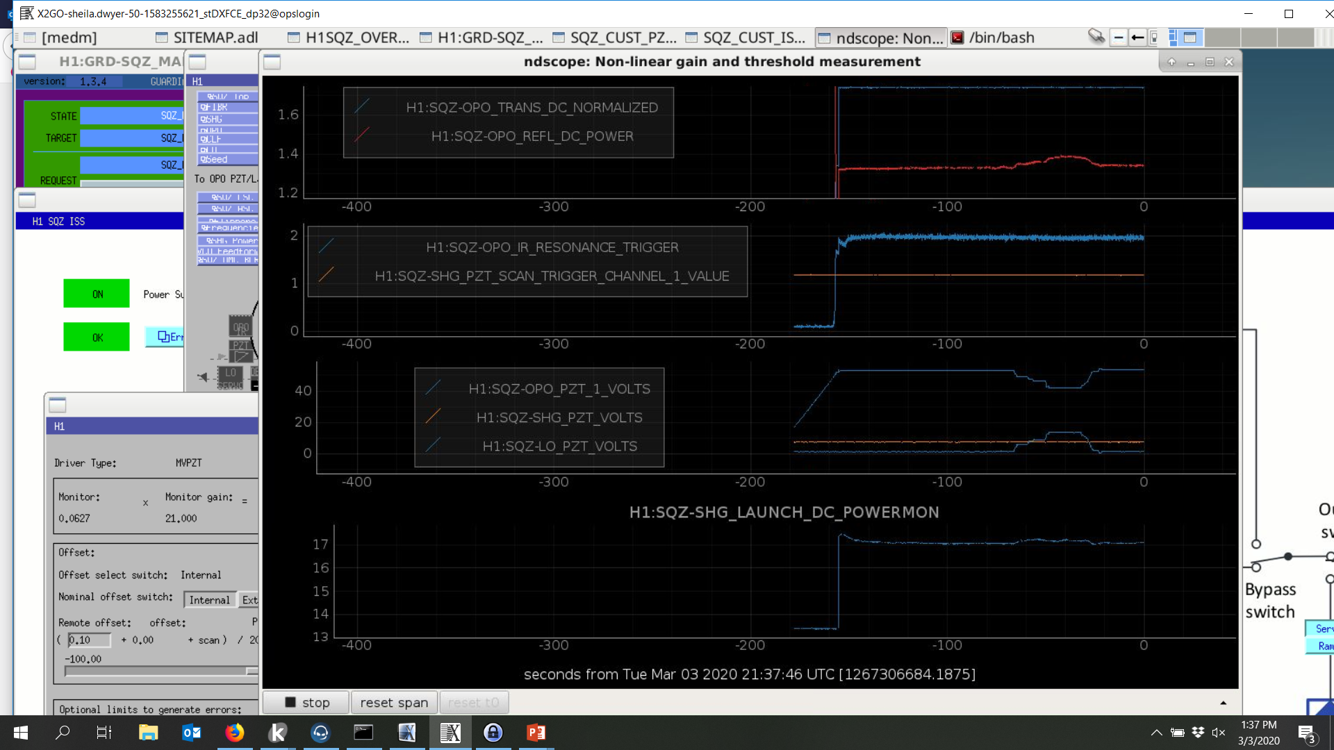
sheila.dwyer@LIGO.ORG - 14:17, Tuesday 03 March 2020 (55400)

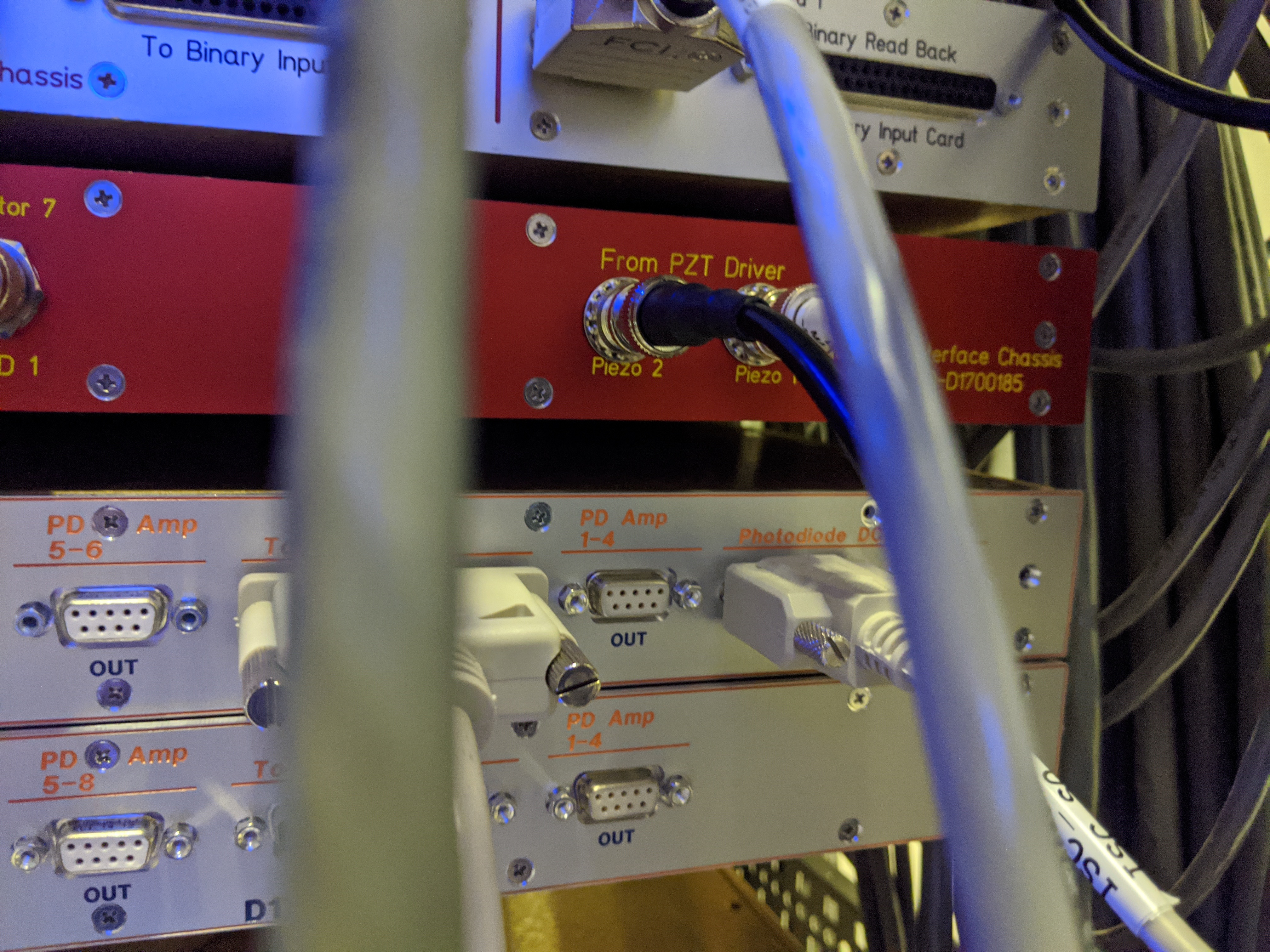
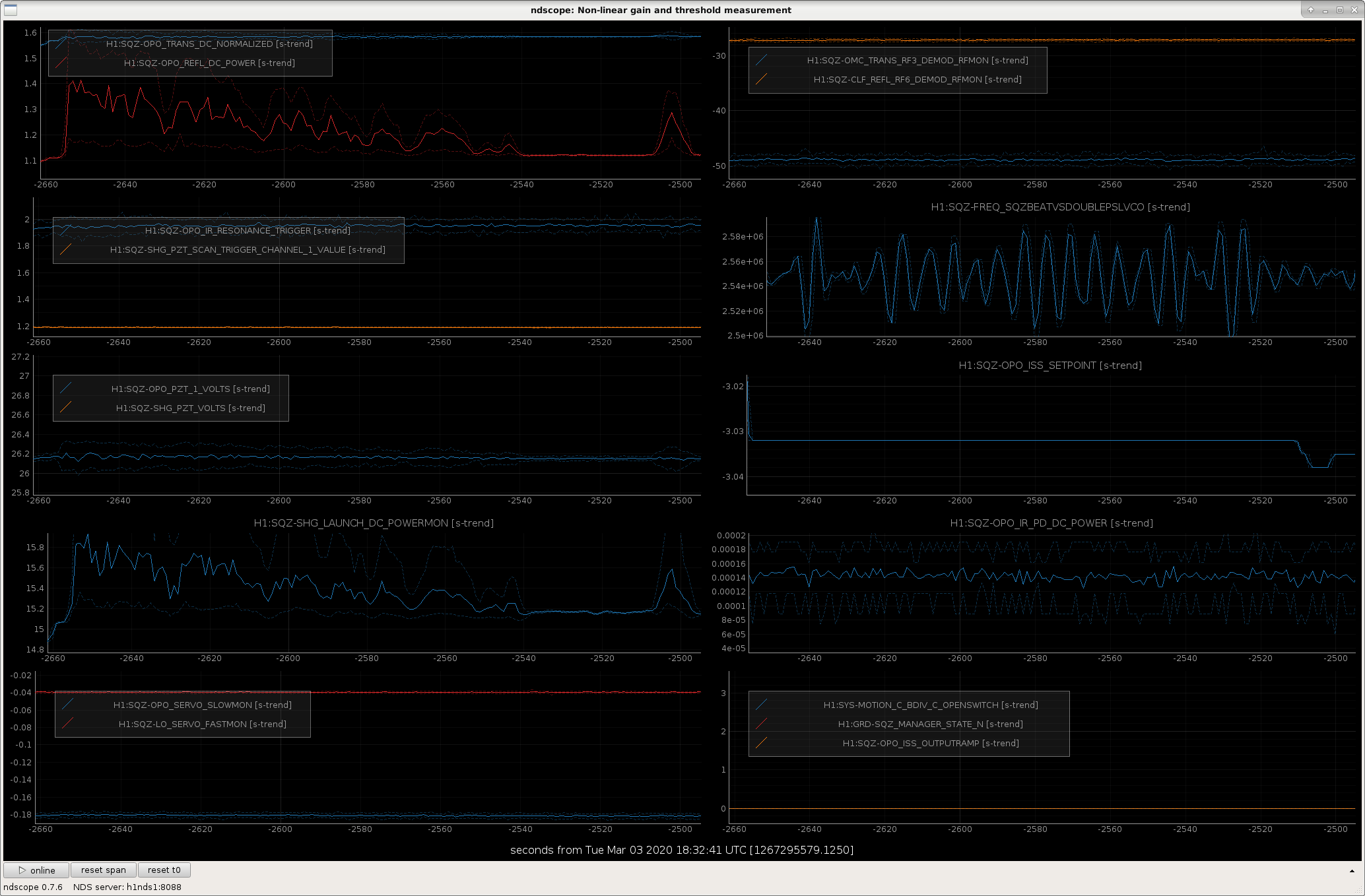
Jenne cabled the LO PZT driver channel (used only for locking with the diagnostic homodyne, not during runing) to the OPO PZT2.  The attached screenshot shows that with the OPO locking using PZT1 (blue line, around 50V), we can move the offset on PZT2 (LO channel, blue line around 0-20V) to reduce the voltage on PZT1. You can see that the reflected power increases when there is a higher voltage on PZT2, which is on one of the curved mirrors, because the cavity gets more misaligned from driving PZT2 than PZT1.  

We tried but weren't able to recreate the oscillation a second time, so we don't know if moving around the offset on the second PZT will have any impact on the instability.  We can try to move this offset if the instability does reappear, although it might not help if the problem is related to the misalignment of the OPO that the high PZT1 voltage causes.

Images attached to this comment
jenne.driggers@LIGO.ORG - 14:51, Tuesday 03 March 2020 (55403)

Keita was wondering if part of the difference (that prevented us from recreating the oscillation) was the fact that both PZTs were connected to cables, neither of them was connected to a terminator.  So, I reverted PZT2 back to being a terminator (and re-plugged in the LO cable to the LO PZT output of the driver).  Now everything cable-wise is back to how it was this morning.  However, I still wasn't able to cause oscillations, even if I brought the green power up above 1.8. 

So, for now I'll leave all of the cables as they are, which is fully reverted from the tests today.  If we see the oscillations come back, then we'll reconsider again borrowing the LO driver channel for PZT2.

jenne.driggers@LIGO.ORG - 14:38, Thursday 05 March 2020 (55456)

When I left things at a green power of 1.3, I had also reverted the squeezer angle, but had forgotten to revert the OPO crystal temperature, H1:SQZ-OPO_TEC_SETTEMP.  I have now reverted it to its value from before last Thursday's green power change (33.014 C).  I did not measure the nonlinear gain.  For this, we were out of Observing for ~1 minute.

H1 ISC
sheila.dwyer@LIGO.ORG - posted 19:11, Monday 24 February 2020 - last comment - 15:50, Tuesday 03 March 2020(55278)
45 minutes of commissioning for DARM offset change tests

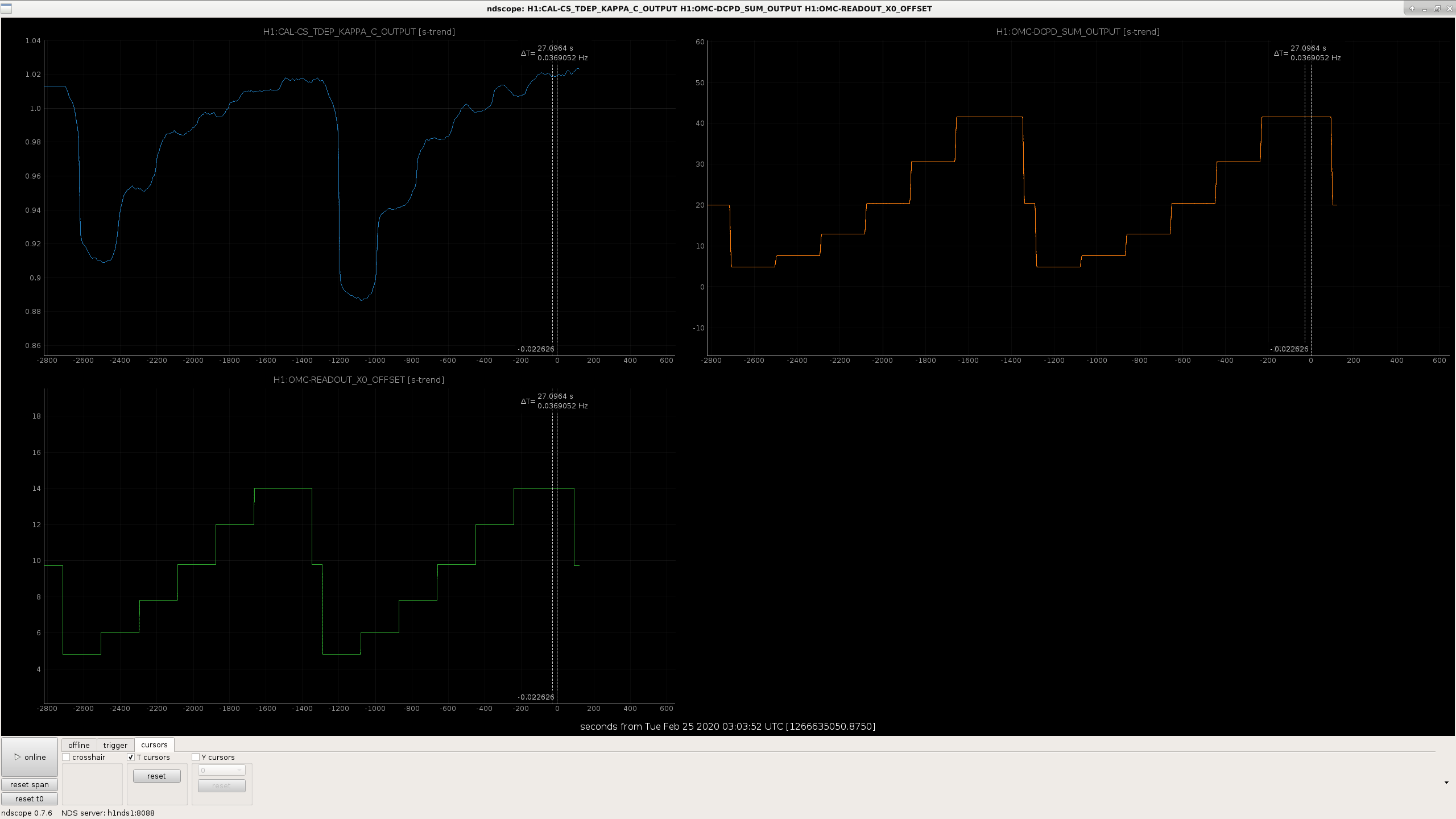
I measured the optical gain for different light levels on the DCPDs before and after lowering the 9MHz modulation depth.  We did this as we relocked. 

The scan started at 2:18:40 UTC Feb 23rd, and went until 3:05:23 UTC


Images attached to this report
Comments related to this report
sheila.dwyer@LIGO.ORG - 10:49, Wednesday 26 February 2020 (55287)

Attached is a plot of the DCPD power vs optical gain during this test.  Although these two traces look similar when plotted this way, there is a consistent difference between the two, and fitting for the amount of junk light inboth cases gives 1.09 +/- 0.06 mA in the high modulation depth measurement, and 1.35+/- 0.06 mA in the low modulation depth case.  

While looking at this data I realized that I had made an error in an earlier alog about modulation depths, which is corrected in the comment now.  Based on the change in modulation depth (first scan taken with a 23.4dBm epics setting on driver, which means 0.189 radians modulation depth, second scan taken at 20.3dBm setting which means 0.159 radians), we would expect that carrier light in the interferometer would be reduced by 0.5% and the sideband power injected would be increased by 40% when the modulation depth is decreased. 

This result suggests that the junk light we are seeing is probably not the 9th order 9MHz mode which is near resonance in H1's OMC 46667.  

One explanation for this result could be that I made the test while the interferometer was still thermalizing.  The attached screenshot shows trends while the measurement was taken, the fastest part of the thermal transient was over. 

There was a 0.8% increase in the circulating power in the Y arm, 0.9% increase in the X arm, when the modulation depth was increased, so both of those are sligthly higher than we expected for the change in modulation depth.  It could be that an alignment set point changes when we change the 9MHz modulation depth, which is generating extra carrier junk light. 

Non-image files attached to this comment
sheila.dwyer@LIGO.ORG - 13:57, Wednesday 26 February 2020 (55316)

The increase in junk light after the 9MHz reduction made Keita and I ask ourselves why we are doing this reduction, and if the tests that motivated the change would have the same outcome in our current configuration.  It seems plausible that the reason this produces junk light (if it does) are related to TCS settings, spot positions and circulating power.

history of 9MHz modulation depth:

  • Sept 2016:
    • 9MHz reduction by 6dB added to guardian after power increase.  29983
    • OMC trans image changed with 6dB reduction in 9MHz; suggestion that 900 Hz peak is reduced by 9MHz reduction, 29817 I seem to remember that this change in the 900Hz peak was not repeatable, we were just being confused by noise which came and went.
    • Identification of 9th order 9MHz mode in transmission through OMC: 29395
  • Nov 2016:
    • 9MHz reduction which was done after power increase is removed from guardian because of locklosses, we weren't sure if it mattered for sensitivity.
  • April 2018:
    • EOM swapped, so dBm settings are not directly comparable before and after this time. 41435
  • late Oct 2018:  
    • Refl 9 slew rate limited: 44771
    • The first result in this alog looks dramatic but if you read all the comments and the story becomes much less clear.  The drive levels being compared aren't written in the alog, but I am infering from the plots that these are comparisons between 23dBm drive setting (nominal at the time, 0.184rad) and 17dBm (called redcued here, 0.130 radians) : 44781
  • Nov 2018:
    • increasing 9MHz by 6dB compared to nominal setting (of 20dBm) makes DARM worse, lowering it doesn't help 45173
    • I am not finding this discussion in the alog, but my memory is that Koji told us that the EOM driver is more noisy when operating at it's max power, so we probably have more 9MHz RIN when we operate at 26dBm on the driver. 
  • Mid Jan 2019: 
    • 46444 we were operating with a 20dBm setting on the 9MHz driver, (0.159 radians 55304) and reported that increasing the drive by 3dBm reduced the range by 10Mpc. (Also estimated sideband/carier ratios on OMC QPDs)
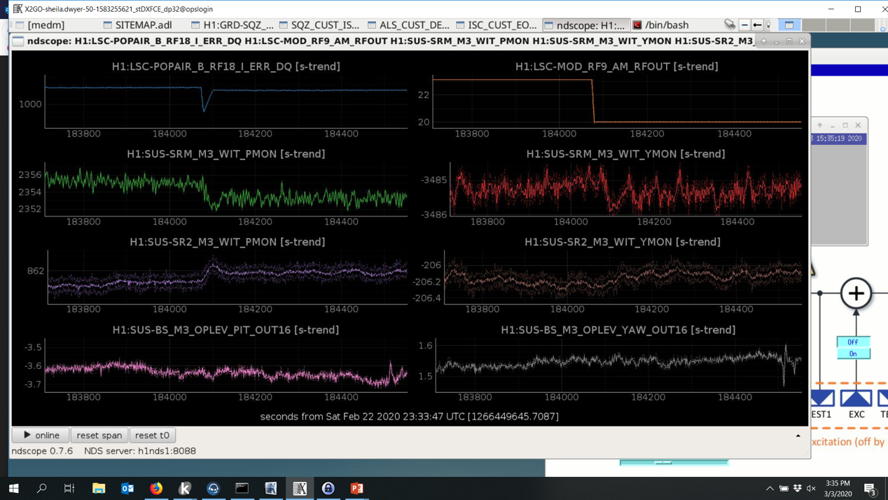
sheila.dwyer@LIGO.ORG - 15:50, Tuesday 03 March 2020 (55405)

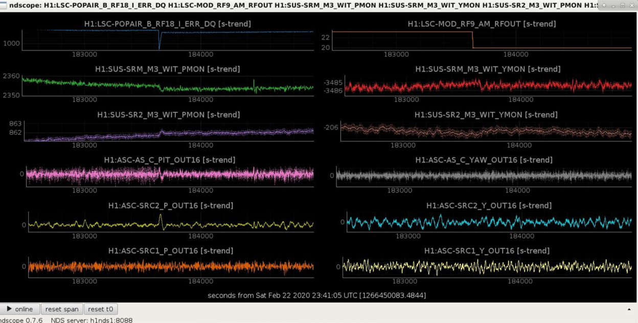
Daniel suggested that we look at what happens to the BS alignment when the modulation depth changes, since AS36 is the signal used to control the BS alignment.  Jenne looked into this and found that the beam splitter doesn't react to the change in modulation depth, but SR2 and SRM both do.  The first attachment shows that this is mostly in pitch, but there is also a yaw reaction. The second attachment shows that the AS-C QPD seems to be the reason why changing this modulation depth changes the alignment of the SRC.  (You can see the change in AS_C before the SRC2 loop brings it back to it's error point by moving the alignment of SR2+SRM).  There is not much happening in the AS72 loop (SRC1), which you would expect if they are well diagonalized. 

This suggests that the amount of junk light we have on the DCPDs can be changed by changing our offset on AS_C.  We plan to try a test of this tomorow.


Images attached to this comment
Displaying reports 35421-35440 of 89220.Go to page Start 1768 1769 1770 1771 1772 1773 1774 1775 1776 End