On Friday (alog 55108) I measured the LSC feedforward filters that we'll need when we re-try increasing our DARM offset. I've now got some candidate SRCL FF filters, although as usual they are tricky to fit.
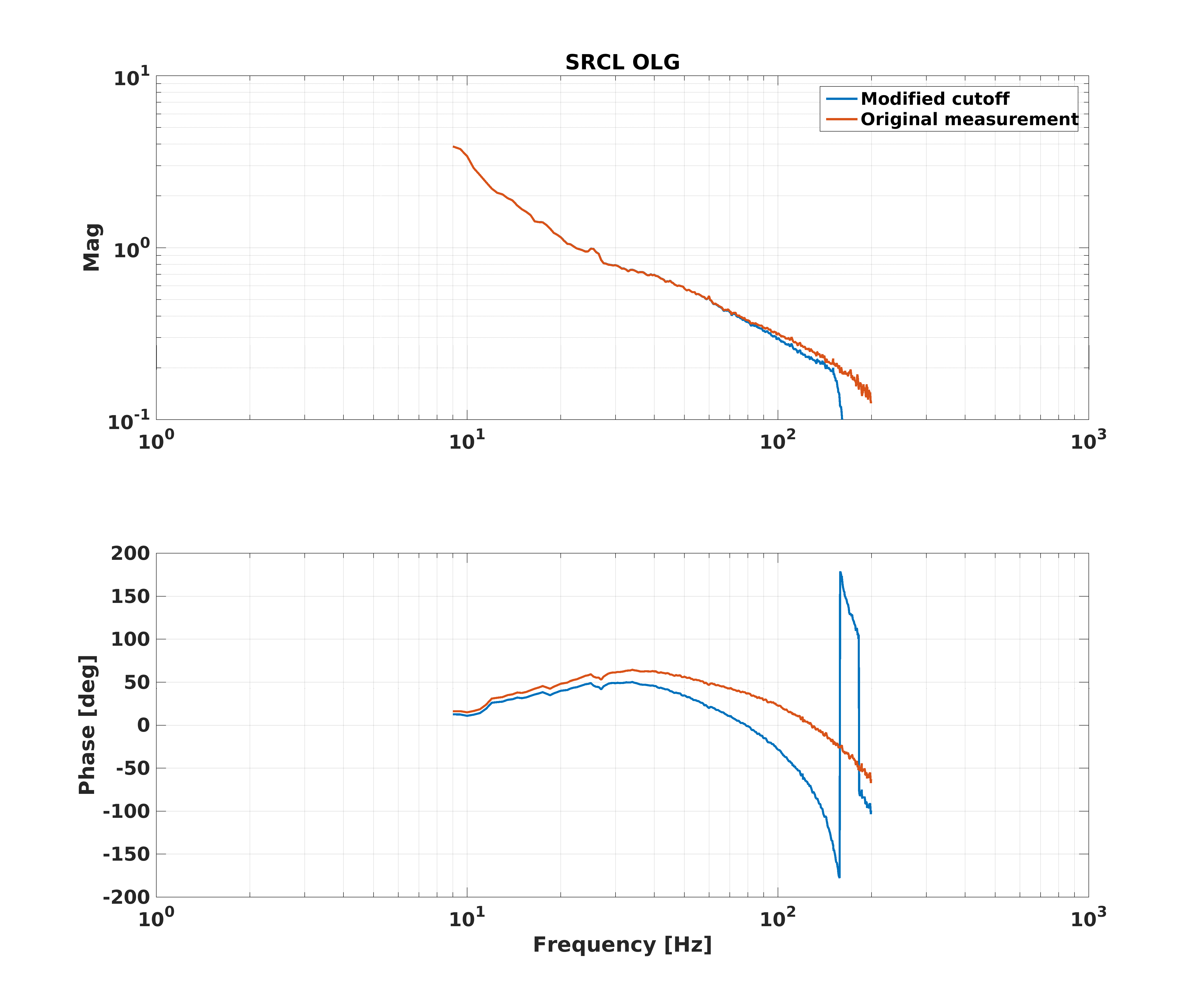
This SRCL FF filter would inject excess SRCL control into DARM above ~150 Hz, since the fit is not good above there. It's hard to convince the fit of the feedforward to maintain high fidelity in the mid frequencies (where we really care) and also roll off the high frequencies. So, an alternate solution might be to more sharply cutoff the SRCL LSC loop. According to our most recent SRCL OLG measurement (albeit from May 2019) we have more than 50 degrees of phase margin in SRCL, so should have some room for additional rolloff.
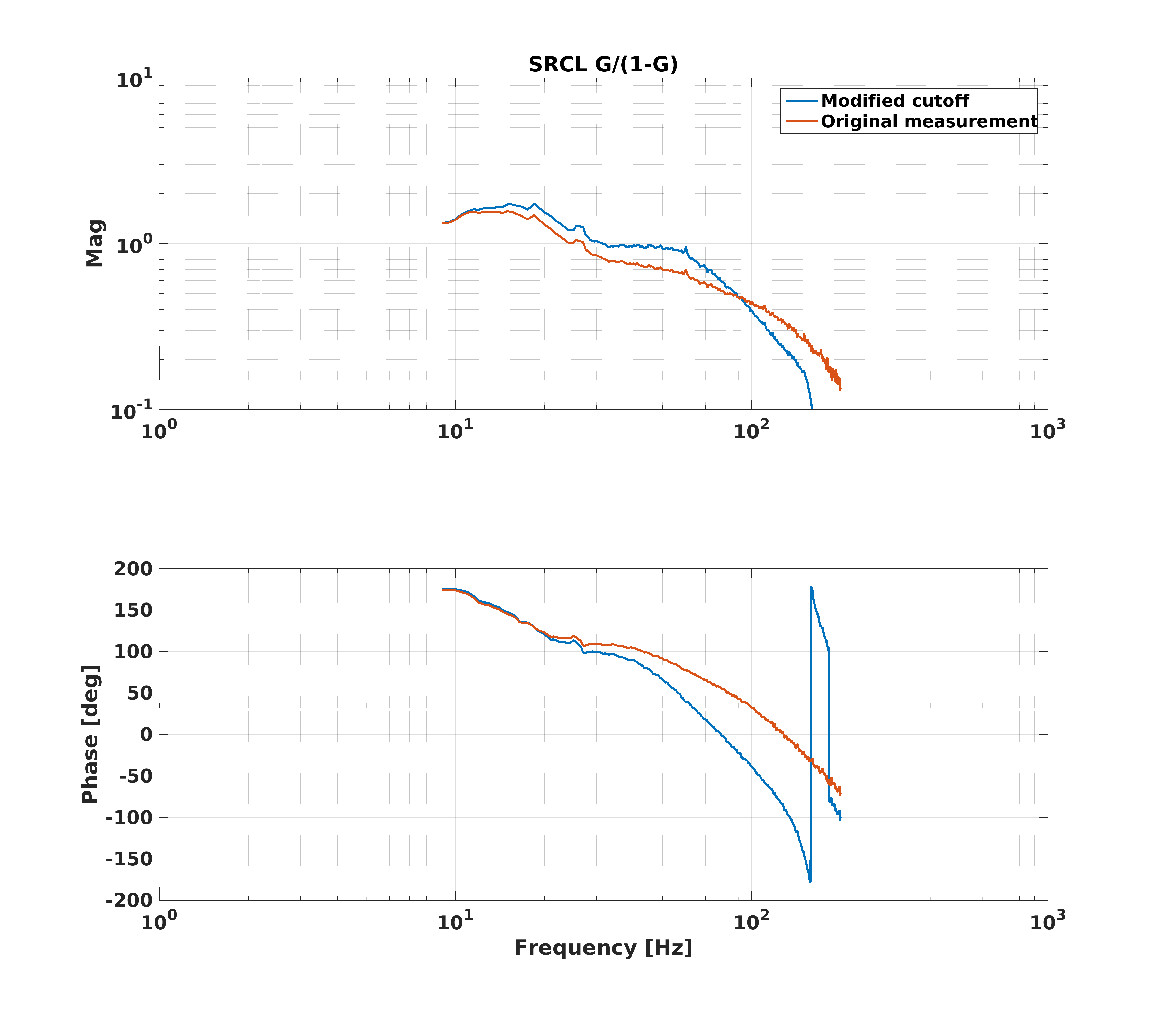
I have created a candidate new SRCL LSC cutoff, and calculated how the change in gain peaking we will expect to see. It seems not so bad, so I propose that before we start our DARM offset test tomorrow morning we measure the SRCL OLG (to confirm that that phase margin is correct), and put in the new cutoff filter. Then we will increase the DARM offset, turn on the new SRCL FF filter, do a quick scan to ensure that we're at the optimal squeezing angle, and then compare this 14 pm DARM offset configuration with our current nominal 10 pm DARM offset configuration.
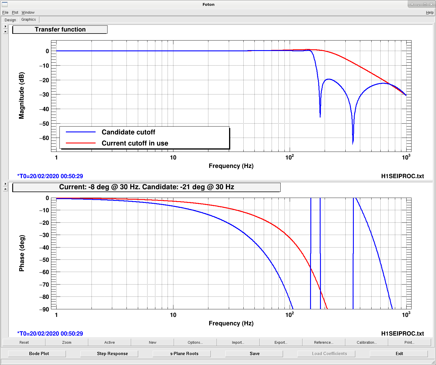
In the first attachment I show the current SRCL LSC cutoff in red versus the candidate cutoff in blue [ ellip("LowPass",4,0.3,20,150)ellip("LowPass",2,1,20,650)gain(1.16145) ]. The candidate filter takes away an additional 13 degrees of phase margin than the current filter.
In the second attachment I show the SRCL OLG measurement from May 2019 in red/orange, and then what that measurement would look like if the cutoff were replaced with the candidate cutoff in blue.
In the third attachment I show G / (1 - G) for both of the cases from the second attachment (current situation in red/orange, and candidate situation in blue).
I think that it should be fine to try the new SRCL cutoff.
All that said, the fourth attachment is my candidate fit for SRCL FF at the higher DARM offset. This is an iterative filter, so if the currently in-use filter were perfect, this iterative filter should be unity. The blue points are the measured TF to fit, and the green is the filter output (IIRrational plus some hand adjustments to make the low frequency and high frequency less egregiously bad). The fit above 150 Hz isn't good, which is why I'm interested in making the SRCL loop cutoff more sharp. The fit also isn't so great below 10 Hz, but at least that part is out of the GW band, and shouldn't hurt us too much when testing the higher DARM offset. The bottom half of the 4th attachment is a representation of how good or poor the fit is to the data.
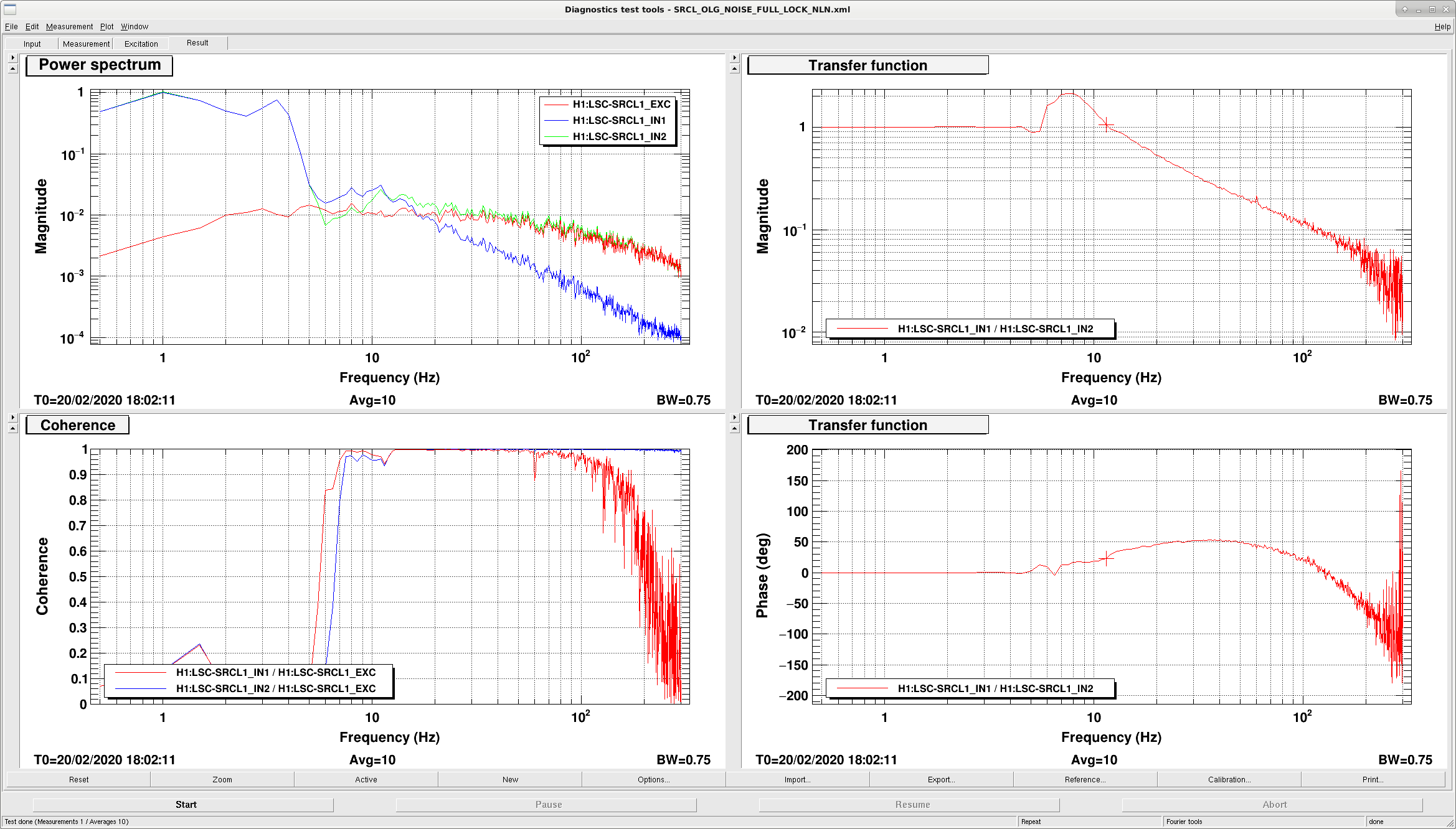
Before changing the cutoff filter, I measured SRCL in NomLowNoise, since the reference measurement I was working from was from May 2019. It seems like the reference measurement was from a time before we lower the SRCL gain, not actually in nominal low noise.
We run SRCL near the very low end of the phase bubble, and so can't afford the phase loss from my proposed new cutoff filter. We tried SRCL FF with higher DARM offset today without any change to the cutoff, and it's mostly fine. Even though there is a teensy bit more coherenece with DARM at ~300Hz, it's still at the 1e-2 level and so shouldn't be a big problem, at least for checking the efficacy of the higher DARM offset.
Spent 30 minutes updating amplitudes for DHARD & CHARD signal injections in 'userapps/asc/h1/scripts/sensingMatrix/run_sensmat.py' - previous values were ~1000x too high.
(Kyle R, Gerardo M)
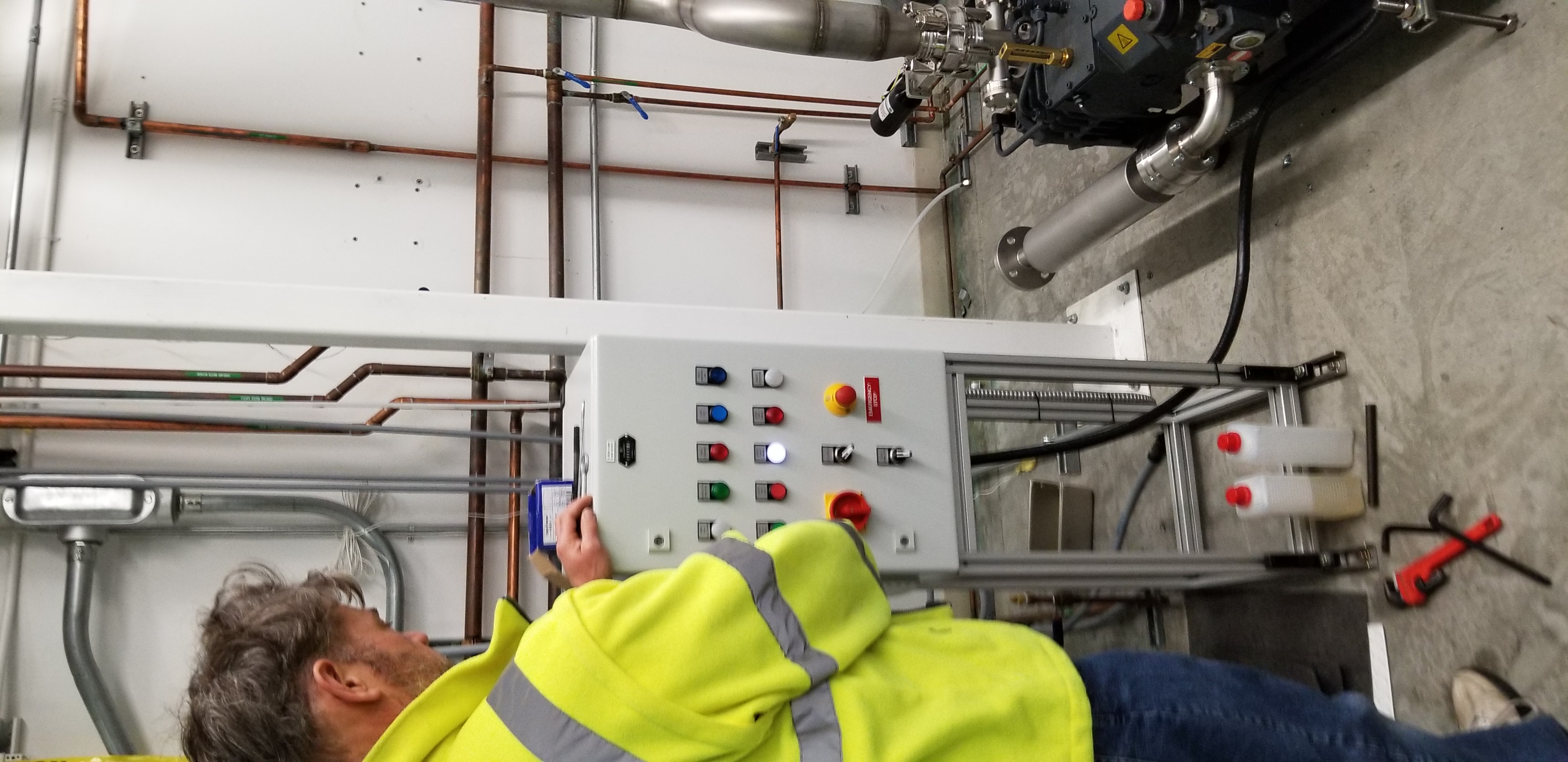
Cooling lines were attached and cooling system was tested for leaks, flow was verified. Oil was added per instruction manual to the gear and bearing chambers. Power was applied to the hepta controller.
The hepta pump was started for a few seconds and stopped manually, the ON time was enough to determine that the direction of the motor is correct, and the pump ran smooth. However we did note a red warning light ON, phase sequence, troubleshooting will be done later about what this error light means.
We did a second start, but this time we allowed for the trouble/error to shut the pump OFF, it almost took the same time as when done manually, once again the pump ran smooth but once again showing the error mentioned above.
Cooling lines were shut off and power was turned OFF for the controller.
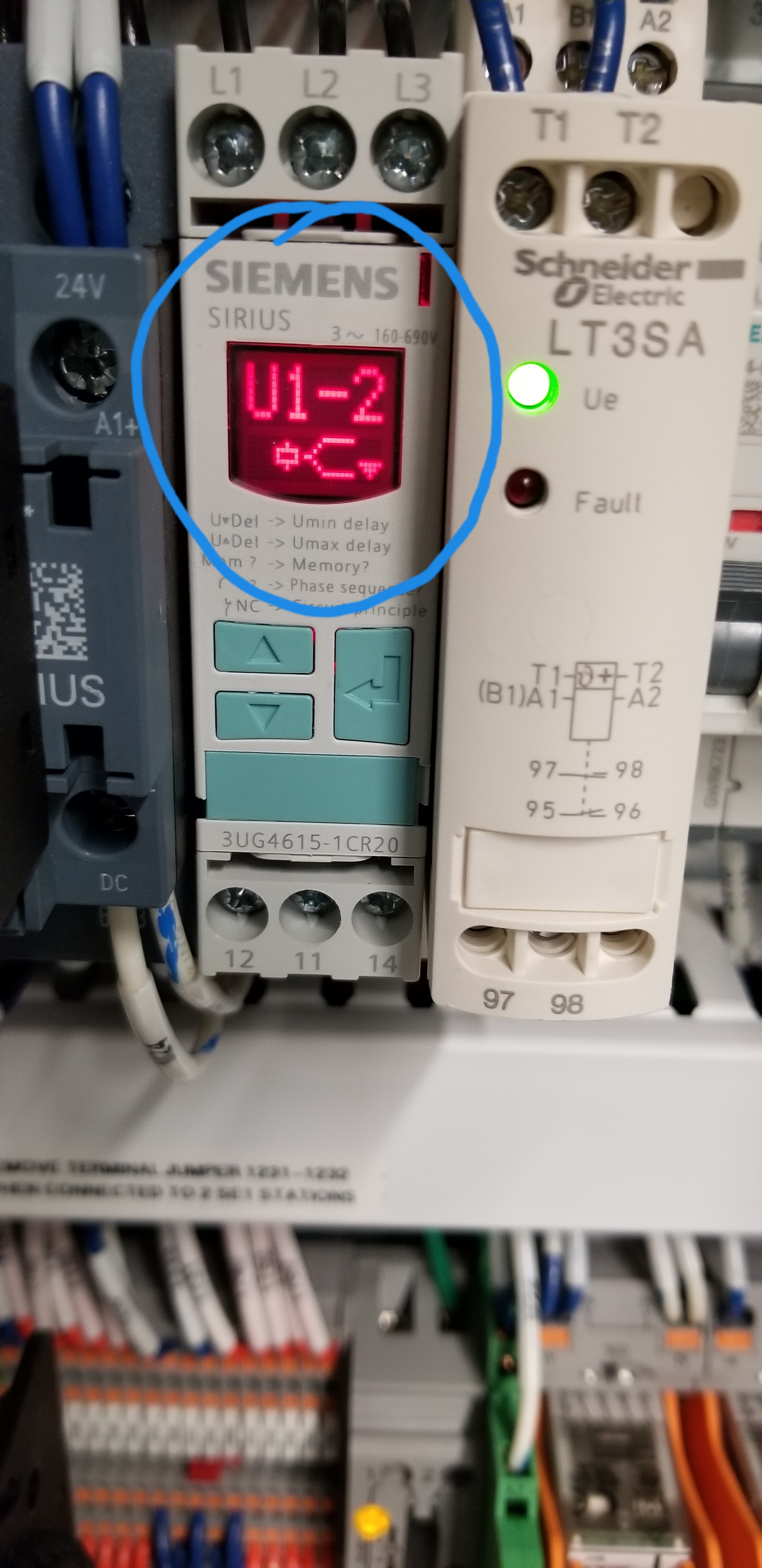
Issue with "phase sequence" error light solved, it turns out that it was not a phase error at all.
A setting for the voltage monitor relay was tripping the system, the undervoltage was set high, see photo for code shown on relay. Setting for the undervoltage was moved to 181 volts and system did not trip anymore.
TITLE: 02/20 Eve Shift: 00:00-08:00 UTC (16:00-00:00 PST), all times posted in UTC
STATE of H1: Observing at 119Mpc
OUTGOING OPERATOR: Jeff
CURRENT ENVIRONMENT:
SEI_CONF state: WINDY
Wind: 9mph Gusts, 8mph 5min avg
Primary useism: 0.02 μm/s
Secondary useism: 0.19 μm/s
QUICK SUMMARY: Just relocked, calm environment.
Started and stopped a few times around 1325 hrs local
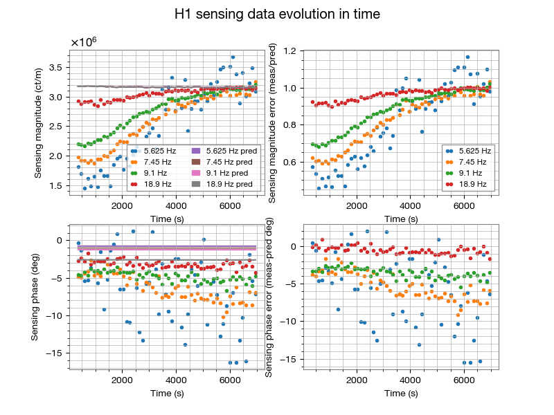
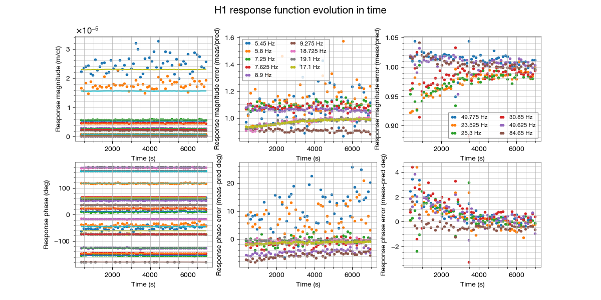
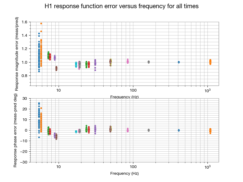
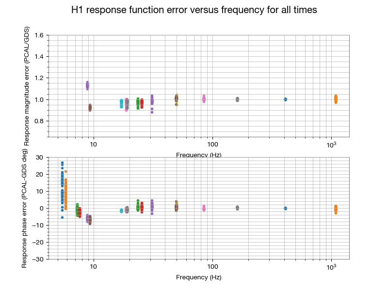
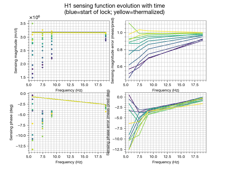
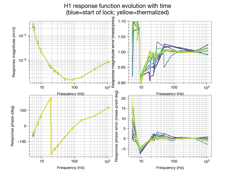
Evan G., Jeff K. We analyzed the data that Jeff collected at the start of a lock stretch (see LHO aLOG 53951) to understand how the sensing function evolves and impacts the response function as the IFO thermalizes. There were indications that the low frequency part of the sensing function was evolving quite a bit more than we expected. To investigate, Jeff had injected a comb of lines using the PCAL and at the DARM excitation point so that we had a measure of the loop suppression to extract the sensing function. This data was analyzed offline using gwpy to compute transfer functions at 2 minute intervals in order to plot the changes as a function of time. Typically the sensing function transfer function swept sine measurements are made when the IFO has thermalized. These injections were at fixed frequencies so that we could track the evolution. Attached are 8 figures: 1) For the 4 frequencies where the sensing function is measured, we plot the time evolution of the sensing function compared to the pyDARM model predicted using the modelparams_H1_20190909.py file and GDS computed f_cc and kappa_c 2) For the 18 frequencies where PCAL is injected, we have measured the response function evolution as a function of time compared to the pyDARM model predicted using the modelparams_H1_20190909.py file and GDS computed f_cc and kappa_c 3) For the 18 frequencies where PCAL is injected, we plot the spread of the data points compared to the pyDARM model predicted using the modelparams_H1_20190909.py file and GDS computed f_cc and kappa_c 4) For the 18 frequencies where PCAL is injected, we plot the spread of the data points compared to the GDS predicted values (this serves as a check that comparing to pyDARM and the GDS computed values is fine). Note that GDS has a high-pass filter of ~10 Hz 5) Sensing function at intervals of 10 minutes to show the evolution as a function of time (BLUE is the start of the lock, YELLOW is the thermalized IFO state) 6) Response function at intervals of 10 minutes to show the evolution as a function of time (BLUE is the start of the lock, YELLOW is the thermalized IFO state) 7) Sensing function at intervals of 10 minutes to show the evolution as a function of time if one also applies the f_s value as computed by GDS, assuming a Q value of 20 (BLUE is the start of the lock, YELLOW is the thermalized IFO state) 8) Response function at intervals of 10 minutes to show the evolution as a function of time if one also applies the f_s value as computed by GDS, assuming a Q value of 20 (BLUE is the start of the lock, YELLOW is the thermalized IFO state) The plotting script is in the CAL svn: ^/trunk/Runs/O3/H1/Scripts/FullIFOSensingTFs/process_sensing_20191217_darm_comb.py The bottom line is in figure 6: at 20 Hz near the beginning of a lock, h(t) is would have a systematic error of ~8% in magnitude and negligible phase. This evolves over the course of ~2 hours, reducing the systematic error close to zero by the end of the 2 hours. We need to compare this with our current uncertainty estimates and evaluate how to proceed if any interesting triggers are occurring in this 2 hour window at the start of a lock stretch.
Good Observing shift so far. Environmental conditions remain favorable. Range is averaging around 119Mpc. No issues of concern at this time. The FMC crew has finished tumbleweed clearing along the X-Arm for the day.
WP8536 Reduce Guardian logs lookback
Jamie, TJ
The Guardian log lookbacks were reduced to 2 months. TJ verified that this improved log retrieval times.
h1iscex IO Chassis new DC power supply
Richard, Keita, Fil, Dave:
The h1iscex front end and IO Chassis were powered down and the IO Chassis was powered from a different +24V power source. Later in the day it was noted that the 21st channel of the second ADC (adc0-ch20) was misreading. Instead of reading -500 counts it was reading +2000. When the cable connecting the ADC to the AA chassis was disconnected, all channels in this ADC went to zero except for chan20 which increased to 10,000. Fil boosted the power and after a second IO Chassis cycle the problem was resolved.
EX Beckhoff hardware restored
Richard, Fil, Dave:
After a week with some photodiodes disconnected from the EX Beckhoff slow controls system, these were restored. The Beckhoff status on the CDS overview went GREEN, I added EX back into the full system summary.
TITLE: 02/19 Owl Shift: 08:00-16:00 UTC (00:00-08:00 PST), all times posted in UTC
STATE of H1: Observing at 118Mpc
INCOMING OPERATOR: Jeff
SHIFT SUMMARY: Other than squeezer range issue
LOG:
12:01 Out of Observing to relock squeezer, see previous alog.
Just noticed that the range has been degrading for the last 2 hours or so. Range had drifted down to about 108 mpc, no apparent environmental causes, wind is low, microseism hasn't changed. Following Sheila's instructions in alog 54967. Seems like the range has recovered, but it took several minutes after relocking the squeezer to see that.
Out of Observe at 12:01 utc, back 12:04.
TITLE: 02/19 Eve Shift: 00:00-08:00 UTC (16:00-00:00 PST), all times posted in UTC
STATE of H1: Observing at 121Mpc
INCOMING OPERATOR: Jim
SHIFT SUMMARY: Once the EX ISC IO chassis was power cycled and the ALS interlock was delt with, it has been smooth sailing.
LOG:
After Keita and Fil were able to get the EX ISC IO chassis working again (alog55171 & alog55173) and then get around the interlock issue (same alogs), it was easy sailing up to Low Noise.
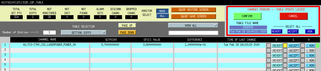
I accepted one SDF that I made adjusting the TCSY CO2 power in calibration.
Camilla pointed out earlier today that the TR offsets that we have hard-coded in the guardian looked like they weren't so good any more. I thought they'd be fine, but then TJ's relocking attempt got stuck because the offset was so bad. So, I updated the values, and now the normalized transmitted arm powers actually look like zero when the arms are not locked in IR.
WP 8537
alog 55041
Ongoing noise hunting efforts at EX continue. Last week we moved auxiliary beckhoff electronics away from the ESD electronics (alog 55041) and powered down the Baffle Photodiode Amplifier chassis.
Today the ISC IO chassis 24V power was moved to same power supply that feeds the SEI IO chassis. Previously the 24V feeding the ISC chassis was also powering the slow controls Beckhoff electronics.
The Baffle Photodiode Amplifier chassis that was turned off last week was powered back on. Leaving unit off showed no change in our lines.
F. Clara, R. McCarthy
Tagging @DetChar and @CAL, in case these changes impact results. I'll post the time of next observation ready segment for which these changes would take affect once we get back up from maintenance.
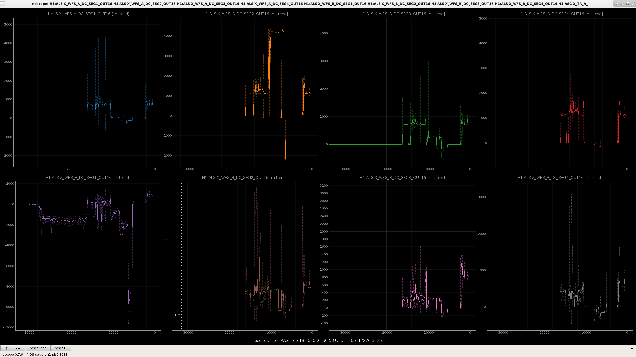
This afternoon Jenne and Camilla had a hard time taking care of green WFS at EX. Turns out that SEG1 of WFSB developed a huge offset of about -2000 counts after the IO chassis was power cycled, and that channel got much noisier too. This was not a sudden change. In the attached, the problem started at about t=-30000 (~ 17:30 UTC) and gradually got worse over the course of tens of minutes.
I was suspicious about analog problem, so I and Fil went to the end station and powered off WFS DC interface as well as AA chassis, but the offset remained. When Fil disconnected the AA chassis from the IO chassis, though, the offset jumped to ~-10k counts, WFSA SEG2 offset also jumped to -2k counts.
Next we power cycled the IO chassis anyway, and that particular problem went away. Don't ask me why.
Then we found, after driving back to the corner, that power cycling IO chassis, or maybe disconnecting AA from IO, triggered the safety system at EX to go crazy, the safety system thought that the status was fine but the laser interlock was kept open so the laser couldn't be turned on. This was manually bypassed.
Sheila, Jenne, Keita
Summary: We have some evidence that our sensitivity can be better with a higher DARM offset.
Details:
Last Thursday I took some data with the squeezer off at different DARM offsets, 55086 to compare with the data that Jenne took 54969.
The high frequency noise is consistent with the measured change in optical gain and the dark noise:
The last two plots show the low frequency sensitivity and the impact of SRCL subtraction, comparing our nominal DARM offset of 10pm to the candidate new offset of 14pm.
I went back and got a few more data points of DCPD current vs optical gain from the time when Jenne moved the DARM offset (54969). Attached is a new version of the 4th attachment above, where the optical gain is plotted against the DCPD power along with a fit to the data (from both times). There are only 2 parameters in the fit, the quadratic coefficient and an offset from junk light which doesn't change with the DARM offset or contain any DARM signal.
This fit suggests that we have 1.7mA of photocurrent from junk light, which would mean 1.95mW of junk light (without the data from Jenne's ealier test we get 1.5mA). This can be compared to the 1.7mW that Craig found in 51273, with 20W of input power.
Summary: I've made an estimate of low frequency noise that could be explained by intensity noise on the junk light that we have on the DCPDs. It is below the DARM residual but within a factor of a few.
If we assume that the low frequency increase in noise at 5pm compared to 14pm is due to intensity noise on the junk light, and assume that intensity noise stays the same when the DARM offset is changed, we can make an estimate of where this noise is when we are operatoing at 10pm.
The first attachment shows the GDS strain data from above with the power based SRCL subtraction, you can more clearly see that there is a low frequency sensitvity difference. If this is due to intensity noise on the junk light, we can use the difference here to estimate the intensity noise. The DARM PSD in displacement is
DARM PSD(5 pm) = Intensity PSD /(optical gain (5pm)^2) + PSD of noises which are independent of DARM offset
and similar for 14pm DARM offset. We can find the Intensity PSD by comparing the two DARM PSDs and knowing the optical gain.
Intensity PSD = [DARM PSD(5pm) - DARM PSD(14pm)]/[1/optical gain(5pm)^2 - 1/optical gain(14pm)^2 ]
The RIN estimated this way is around 5e-8 at 40Hz, shown in the second attachment. The third attachment shows the estimated intensity noise scaled by the optical gain at our nominal DARM offset of 10pm. We can compare this to the attached noise budget residual This is a noise budget for Jan 20th, although we haven't updated the coupling measuremetns used here in several months. The reason that the noise budget misestiamted the quantum noise around 200 Hz is that we don't have the frequency dependence of the squeezer modeled correctly here). The peak at around 48Hz in this noise budget total is from a vibration noise estimate from the PEM website before the 48Hz peak was fixed, this peak should go away when we update that. The message is that the noise I'm estimating to be caused by junk light intensity noise is about half of our noise budget residual at 50Hz, and about a third of the residual at 40 Hz. We would need 4 noise sources of this size to explain our residual at 50Hz, and 8 noise sources this size to explain our residual at 50Hz).
No obvious cause.
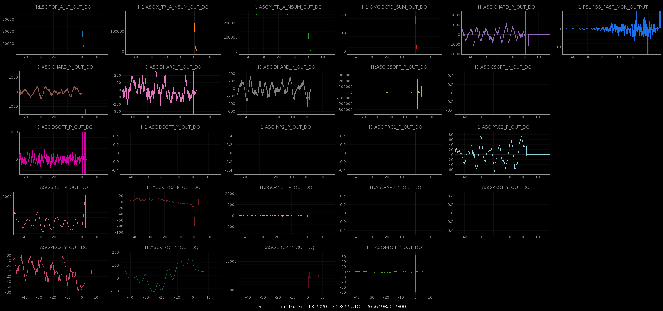
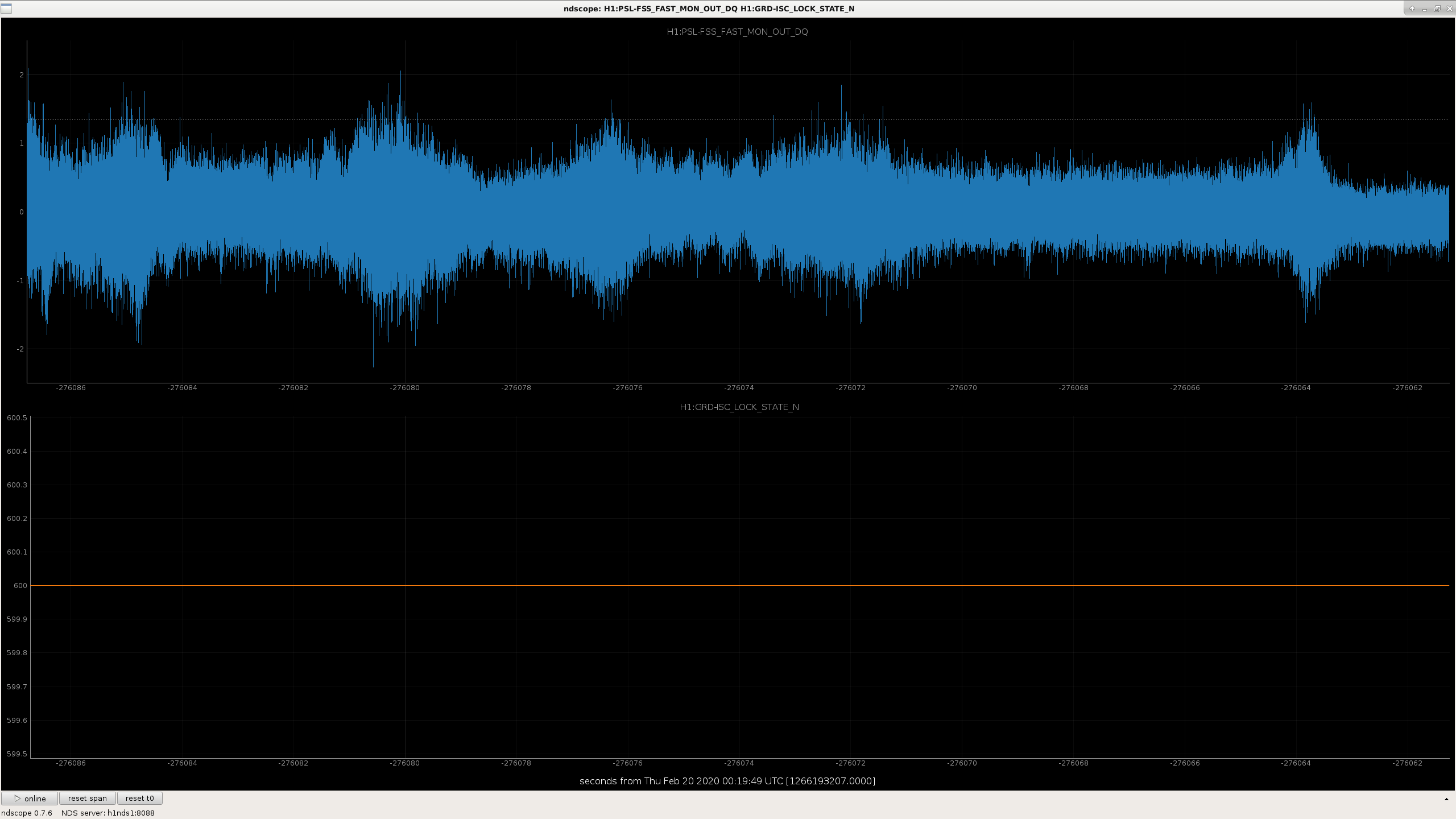
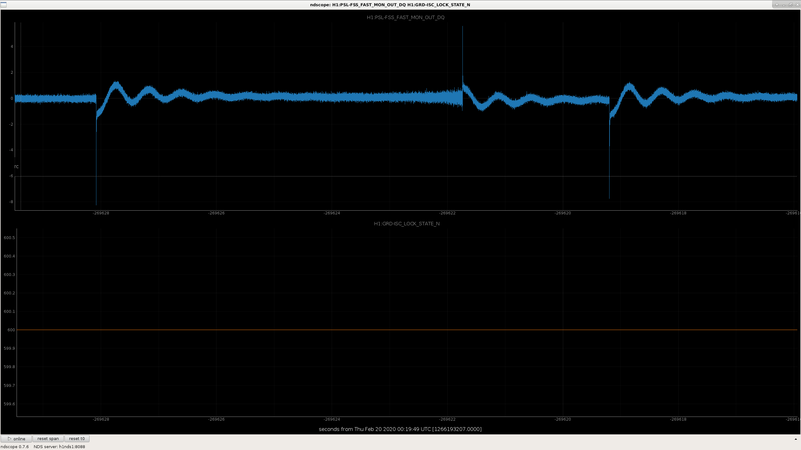
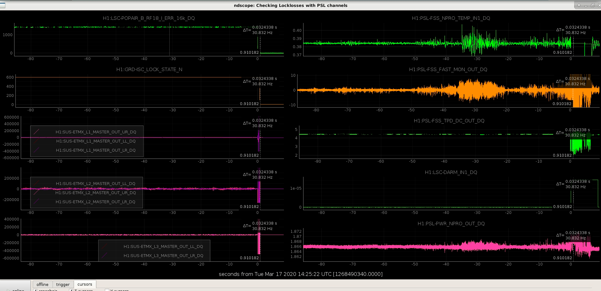
The FSS started to oscillate about 150seconds 30seconds before we lost lock. During relocking we keep losing lock at various places and there is slight motion seen in the Ref Cav Trans spot.
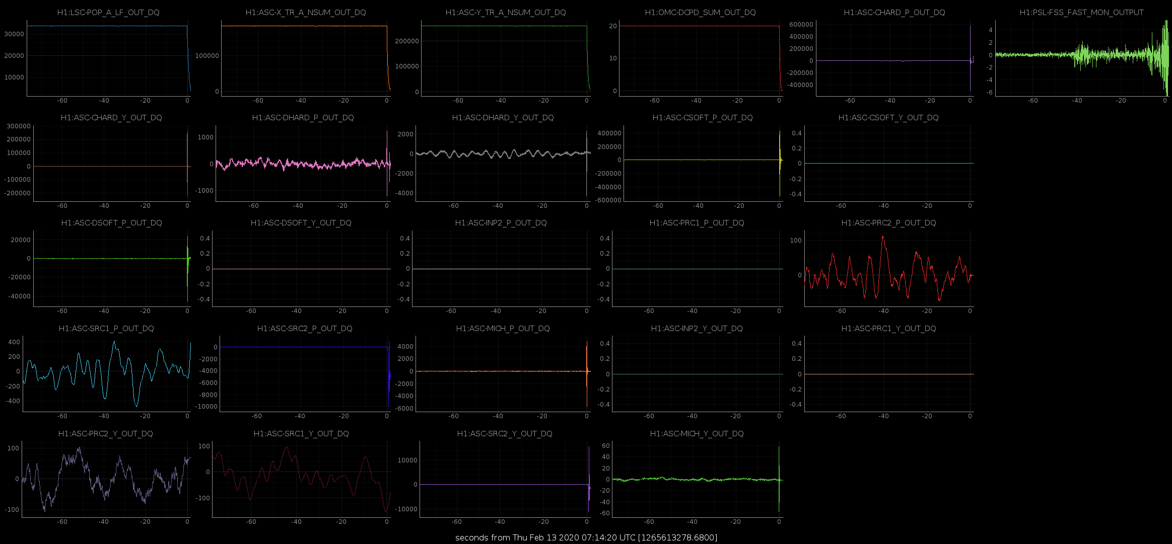
The lock loss at 0714 UTC looks similar as well. Something is seen in that channel 45 seconds before.
Vlad, S.Karki, D. Barker
We pushed the Pcal Simulink model and MEDM screen that Shivaraj generated at LLO (LLO alog 49839). The updated suspension filter files (LHO alog 53155) have been loaded into the corrponding Pcal filter banks as well.
The new calibration coefficients have been uploaded to the appropriate EPICS variable using the txt files linked below:
aligocalibration/trunk/Runs/O3/H1/Results/CALCS_FE/lho_yend_pcal_epics_created-20191111.txt
aligocalibration/trunk/Runs/O3/H1/Results/CALCS_FE/lho_xend_pcal_epics_created-20191111.txt
While quacking the susmodel we encounted a number of issues:
1) The filterfile had to be copied to a local directory and qucked there, as the quacking script would give errors concerining the new SOS coefficients (reason unknown)
2) The quack script only updates gains and SOS coeffcients of the respective filter modules. It does NOT update the desgng strings (the commented out lines that describe what the filter is). Attemting to run "foton -c" (something that needs to be done to parse the foton filters correctly) on the filter file would result in foton detecting a difference between the design string and the real filter, and would take the design string and overwrite your brand new filters.
The workaround to the second problem (thanks to Shivaraj) was to delete the design string before running "foton -c", forcing foton to regenerate it.
The first observation ready segment that had these updates included started on Nov 12 2019 at 22:58:33 UTC, i.e. 1257634731. Thus, prior to these updates, in O3 (i.e. from April 1 2019 to Nov 12 2019) the LHO PCAL Y RX PD (the PCAL PD we use for our absolute displacement reference) had a systematic error of +0.43% -- see the "change" field for LHO Y_end of the RXPD table pg 9 of G1902259. In those slides, the +0.43% is defined as xi = [ (after - before) / before ]*100 = [(after/before) - 1]*100. (1) *** Note that this definition has been defined previously in Eq. (1) of LHO aLOG 52837. Which means that the previous relationship between xi and eps still holds, AFTER NOW TRUTH dL_pcal' (1 + xi/100) = ----- = --------- = --------- = -------- = eps. (3) BEFORE EARLIER APPARENT dL_pcal (and I've used the same equation numbering from that aLOG) This means, for PCAL data prior to Nov 12 2019, should be corrected by PCAL_nosyserror = eps * PCAL_withsyserror = (1.0043) * PCAL_withsyserror (2) where I've again used the same equation numbering scheme as in LHO aLOG 52837, for consistency. That means for all measurements taken and processed before Nov 12, they need the following action taken (assuming that I've already applied the necessary 1/f^2 "anti-whitening" filter and AA filter corrections to PCAL_RXPD): PCAL_RXPD DARM_IN1 A_i == --------- * ---------- DARM_IN1 i_SUSEXC PCAL_RXPD(TRUTH) DARM_IN1 eps * PCAL_RXPD(APPARENT) DARM_IN1 >> A_i(TRUTH) = ---------------- * ---------- = ------------------------- * ---------- = eps * A_i(APPRARENT) DARM_IN1 i_SUSEXC DARM_IN1 i_SUSEXC or A_i(NO PCAL SYS ERR) = eps * A_i(W/ PCAL SYS ERR) DARM_IN1 DARM_EXC C == --------- * -------- PCAL_RXPD DARM_IN2 DARM_IN1 DARM_EXC 1 DARM_IN1 DARM_EXC 1 >> C(TRUTH) == ---------------- * -------- = ----- * ------------------- * -------- = ----- * C(APPARENT) PCAL_RXPD(TRUTH) DARM_IN2 eps PCAL_RXPD(APPARENT) DARM_IN2 eps or C(NO PCAL SYS ERR) = (1/eps) * C(W/ PCAL SYS ERR) The reason I call this out explicitly, is because in O3A (i.e. for LHO aLOG 52837), *ALL* sensing and actuation measurements used to produce the uncertainty budget were "corrupted" by this PCAL systematic error. This is why, in that aLOG, we could "get away" with just multiplying the *entire response function* and/or h(t) by eps (as shown in Eqs. 6-8 of that aLOG). With the new 2020-01-03 model that's to be installed today we cannot. We've *re*processed data from O3A, and some of the measurements from O3B which are prior to Nov 12 are being used as well -- in the same estimate of A_i and C systematic error as those measured *after* the PCAL fix on Nov 12. So, before feeding the A_i and C's from each measurement before Nov 12 in to the measurement collection pool that informs the GPR fitting, I need to correct for eps.
PCAL_RXPD(TRUTH) DARM_IN1 eps * PCAL_RXPD(APPARENT) DARM_IN1
>> A_i(TRUTH) = ---------------- * ---------- = ------------------------- * ---------- = eps * A_i(APPRARENT)
DARM_IN1 i_SUSEXC DARM_IN1 i_SUSEXC