david.barker@LIGO.ORG - posted 10:36, Saturday 20 September 2025 (87036)
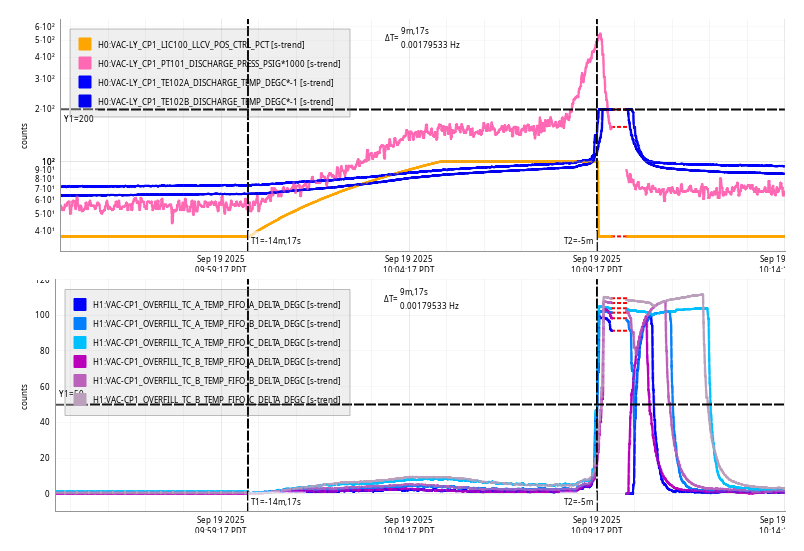
Sat CP1 Fill did not run at scheduled time 10:00. Running it now at 10:35
Haven't seen this for a while, but CP1 code must have skipped the 10:00:00 start time. I've manually loaded an temporary config to run at 10:35:00, it is running now.


03:47 UTC Observing