I installed a new daqd to test raising the connection count for nds1. The server h1nds2 is running a daqd build with a higher connection limit. The code was build from the branch-3.2.x-consumer-limits branch of advLigoRTS. I had to cherry pick 54fca2af32c1643ae2f571cb360526616ea0b158 to update the comm.y file to work with a 'newer' version of bison. It has passed the initial test of running 80 simultanious streams (the fix is not a rearchitecting of the connection and buffer tracking code which would be needed to make it truely arbitrary, but an expanding of the current way of tracking things to hold a few more conenctions).
To test against this server run the following in your shell/console and then launch your program (from that same shell/console):
export LIGONDSIP=h1nds2
export NDSSERVER=h1nds2:8088
or manually connect to h1nds2:8088
The "Phase" of the OSC9 line for the PCALY excitation at 1153.1 Hz was changed from -15 deg to 0 deg.
The amplitude of the 1153.1 line for PCALX was changed from 5000 to 5007.
The 5007 ct amplitude was determined by looking at the ratio of the Xend to Yend Pcal Rx signals and adjusting the amplitude to bring it clost to 1.
(note that the "Cos Ampl" field was bland for this excitation at Xend; it was updated to match the "Sin Ampl" value.
WIth 0.1 Hz BW and 50 averages, the X/Y ratio of the line amplitudes at 1153.12 Hz was (1.00002236, 1.00005868, 0.999899413) for three consecutive 50-avg measurements.
The original configuration of these lines can be found in entry 51915 in this log from Sept. 11, 2019.
WP 7959
Ran cabling from LY vacuum rack to HAM4 and HAM6 RGA's. Slow Controls Vacuum Chassis will need to be modified for new signals.
Network cable was pulled from HAM6 RGA to SUS-R3 patch panel for remote monitoring of the RGA.
All three dust monitor vacuum pumps are working great. Made no adjustments to pressures. All temps were well within the specified operations range. Noted no carbon dust accumulation on the mufflers.
Closing FAMIS Task #13000
No apparent leaks and no problems observed.
Closing FAMIS #13490
Vlad, S.Karki, D. Barker
We pushed the Pcal Simulink model and MEDM screen that Shivaraj generated at LLO (LLO alog 49839). The updated suspension filter files (LHO alog 53155) have been loaded into the corrponding Pcal filter banks as well.
The new calibration coefficients have been uploaded to the appropriate EPICS variable using the txt files linked below:
aligocalibration/trunk/Runs/O3/H1/Results/CALCS_FE/lho_yend_pcal_epics_created-20191111.txt
aligocalibration/trunk/Runs/O3/H1/Results/CALCS_FE/lho_xend_pcal_epics_created-20191111.txt
While quacking the susmodel we encounted a number of issues:
1) The filterfile had to be copied to a local directory and qucked there, as the quacking script would give errors concerining the new SOS coefficients (reason unknown)
2) The quack script only updates gains and SOS coeffcients of the respective filter modules. It does NOT update the desgng strings (the commented out lines that describe what the filter is). Attemting to run "foton -c" (something that needs to be done to parse the foton filters correctly) on the filter file would result in foton detecting a difference between the design string and the real filter, and would take the design string and overwrite your brand new filters.
The workaround to the second problem (thanks to Shivaraj) was to delete the design string before running "foton -c", forcing foton to regenerate it.
The first observation ready segment that had these updates included started on Nov 12 2019 at 22:58:33 UTC, i.e. 1257634731. Thus, prior to these updates, in O3 (i.e. from April 1 2019 to Nov 12 2019) the LHO PCAL Y RX PD (the PCAL PD we use for our absolute displacement reference) had a systematic error of +0.43% -- see the "change" field for LHO Y_end of the RXPD table pg 9 of G1902259. In those slides, the +0.43% is defined as xi = [ (after - before) / before ]*100 = [(after/before) - 1]*100. (1) *** Note that this definition has been defined previously in Eq. (1) of LHO aLOG 52837. Which means that the previous relationship between xi and eps still holds, AFTER NOW TRUTH dL_pcal' (1 + xi/100) = ----- = --------- = --------- = -------- = eps. (3) BEFORE EARLIER APPARENT dL_pcal (and I've used the same equation numbering from that aLOG) This means, for PCAL data prior to Nov 12 2019, should be corrected by PCAL_nosyserror = eps * PCAL_withsyserror = (1.0043) * PCAL_withsyserror (2) where I've again used the same equation numbering scheme as in LHO aLOG 52837, for consistency. That means for all measurements taken and processed before Nov 12, they need the following action taken (assuming that I've already applied the necessary 1/f^2 "anti-whitening" filter and AA filter corrections to PCAL_RXPD): PCAL_RXPD DARM_IN1 A_i == --------- * ---------- DARM_IN1 i_SUSEXC PCAL_RXPD(TRUTH) DARM_IN1 eps * PCAL_RXPD(APPARENT) DARM_IN1 >> A_i(TRUTH) = ---------------- * ---------- = ------------------------- * ---------- = eps * A_i(APPRARENT) DARM_IN1 i_SUSEXC DARM_IN1 i_SUSEXC or A_i(NO PCAL SYS ERR) = eps * A_i(W/ PCAL SYS ERR) DARM_IN1 DARM_EXC C == --------- * -------- PCAL_RXPD DARM_IN2 DARM_IN1 DARM_EXC 1 DARM_IN1 DARM_EXC 1 >> C(TRUTH) == ---------------- * -------- = ----- * ------------------- * -------- = ----- * C(APPARENT) PCAL_RXPD(TRUTH) DARM_IN2 eps PCAL_RXPD(APPARENT) DARM_IN2 eps or C(NO PCAL SYS ERR) = (1/eps) * C(W/ PCAL SYS ERR) The reason I call this out explicitly, is because in O3A (i.e. for LHO aLOG 52837), *ALL* sensing and actuation measurements used to produce the uncertainty budget were "corrupted" by this PCAL systematic error. This is why, in that aLOG, we could "get away" with just multiplying the *entire response function* and/or h(t) by eps (as shown in Eqs. 6-8 of that aLOG). With the new 2020-01-03 model that's to be installed today we cannot. We've *re*processed data from O3A, and some of the measurements from O3B which are prior to Nov 12 are being used as well -- in the same estimate of A_i and C systematic error as those measured *after* the PCAL fix on Nov 12. So, before feeding the A_i and C's from each measurement before Nov 12 in to the measurement collection pool that informs the GPR fitting, I need to correct for eps.
PCAL_RXPD(TRUTH) DARM_IN1 eps * PCAL_RXPD(APPARENT) DARM_IN1
>> A_i(TRUTH) = ---------------- * ---------- = ------------------------- * ---------- = eps * A_i(APPRARENT)
DARM_IN1 i_SUSEXC DARM_IN1 i_SUSEXC
Operators have been running into a situation where the ALS IR serach is very sensitive to the dark offsets in the transmon QPDs being wrong. We (Jenne, Betsy and I) discussed raising the threhsold that is used in the fine_tune_IR states (for both comm and diff) I've reset the threshold in ISC_gen_states so that IR fine tune only happens when we have a normalized transmission above 0.1 (10% of on resonance transmission). Previously the threshold was 0.02
I've loaded both ALS_COMM and DIFF guardians, we will see if this helps us avoid operators needing to reset dark offsets in FIND_IR
I reset both PSL power watchdogs at 19:27 UTC (11:27 PST). This completes FAMIS 10736.
Chiara, Conor
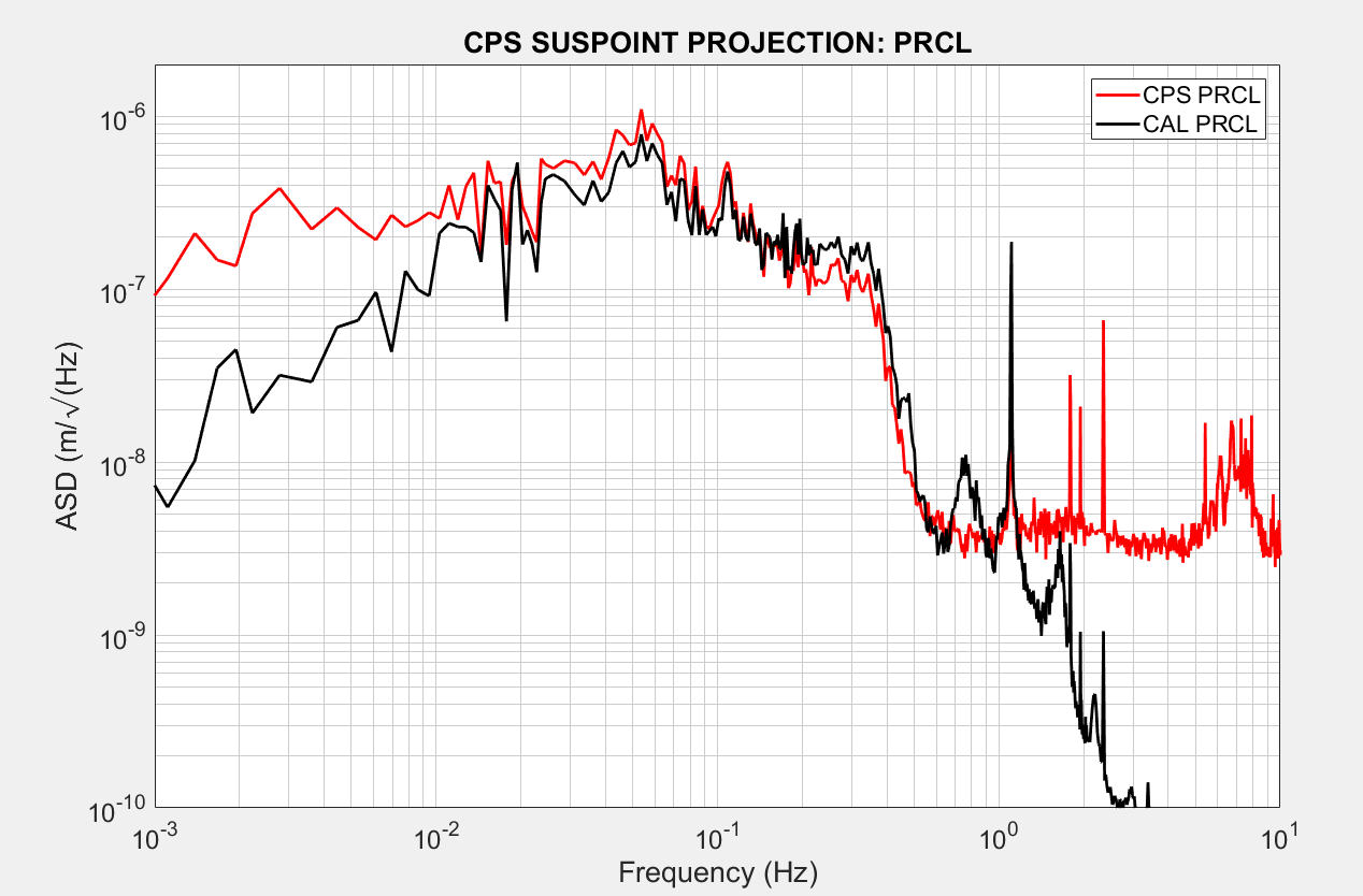
We checked CAL_PRCL and despite implementing the M1 calibration change:
https://alog.ligo-wa.caltech.edu/aLOG/index.php?callRep=53160
The low-frequency calibration seems to be much improved, right down to the 8mHz AC-coupling cut-off.
There is still the problem of high-frequency excess noise, but for now this will be useful for PRCL/CPS-diff control tests.
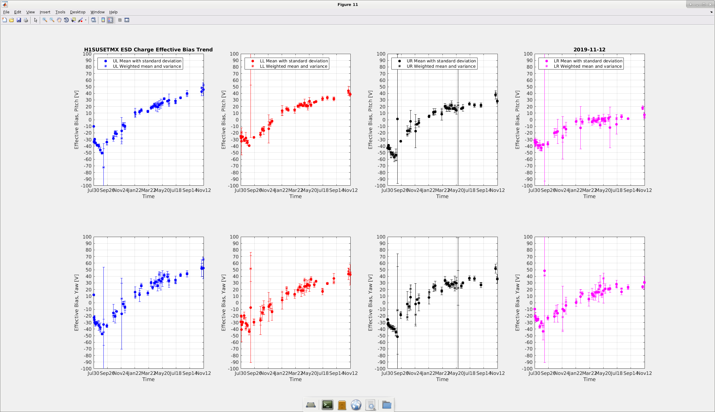
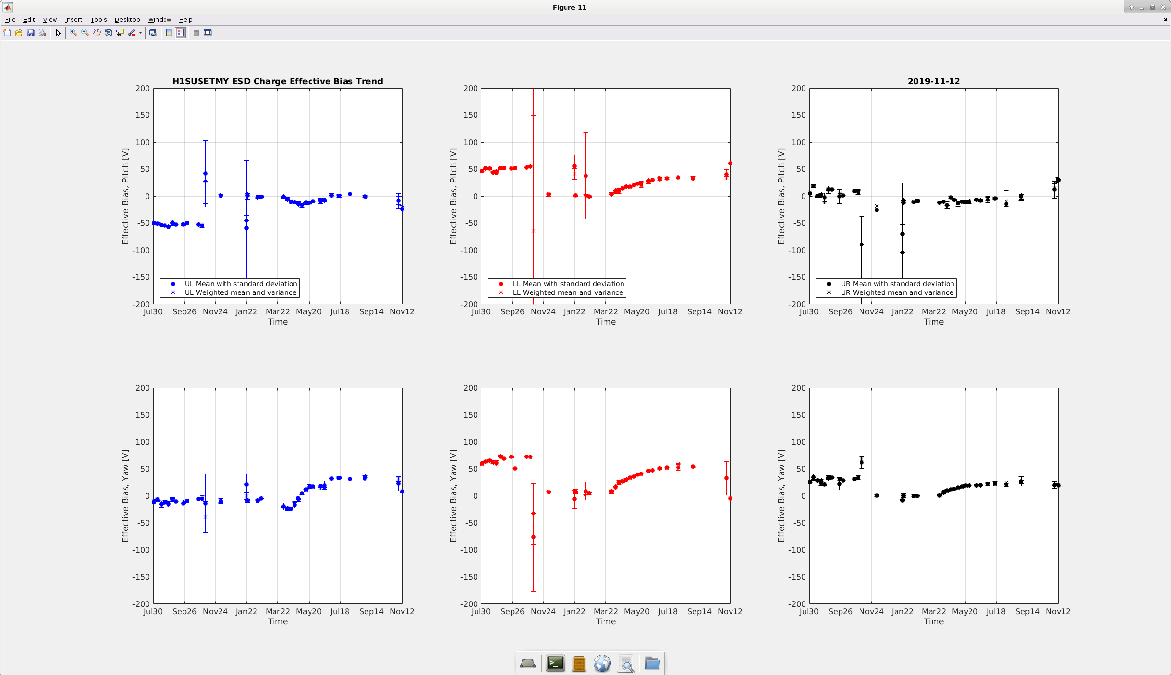
Last week the effective bias voltage on the test mass mirrors were showing an upwards trends, hence we decided to take another measurements this week to see how things are going (else this is a monthly exercise now). Seems like ETMX seems to have improved (or rather say distributed the charge) for some quadrants. Overall everything looks to be within limits (which is +-50V). Similarly, on ETMY, there is drop in the charge accumulation (except for the 1nd quadrant for the Pitch, which is above 50V).
All the slider values were restored after the measurements and SDF difference checked and removed.
F. Clara, M. Pirello
We tested the readback channels out of the I&Q Demod chassis (S1001015) located at ISC-R3 position 11. The outputs looked correct, so we followed the signal back to the concentrator chassis located in ISC-R5. We discovered gender changers for both outputs of this chassis which were poorly attached. This loose connection was the cause of the faulty readback. We replaced the DB9 cables and eliminated the gender changers. The new cables are ISC_SQ_306 and ISC_SQ_307 they were both changed from M-M to M-F. This closes WP8465 and solves ALOG53030.
Marc Daniel
Today we checked on a voltage offset problem in the OPO ISS. This manifested itself with a control monitor readback that was several volts different from the drive point input, when the servo was off.
While hooking up the tester we noticed that the gain stages were cross wired through software. This required a TwinCAT fix and restart. Finally, we traced the voltage offset to a busted OmAmp in the ramp input. This device was replaced and the chassis is now working correctly.
I increased the pressure at GV 6,8 gate piston from 55 psig (GV6) and 52 psig (GV8) to maximum (~ 85 psig) and then valved out instrument air from compressor and valved in instrument air from bottled N2 in mechanical room. Kyle has already maximized pressure at GV 5,7. GV5 is reading ~90 psig, but GV7 is sitting at 60 psig.
Worth noting that when I increased the pressure at GV6, I heard a noise of the gate moving, suggesting it wasn't fully lifted. A wiggly gate could have been a noise source. Request for DetChar/PEM to measure affects of instrument air (what we've been calling compressor noise) after this change this morning at around 8:30 am local (16:30 UTC). The compressor is not off, but now GV6 gate is fully lifted.
I will monitor the bottle pressure every hour and valve it out and compressor back in before I leave today. We are keeping a spreadsheet of bottle consumption.
WP 8460
Valved out bottled gas and valved back in compressor air at 1pm local.
This is to document that at the beginning of O3b, before the new O3b uncertainty envelope is ready, onlinePE is using the last C00 O3a envelope:
TITLE: 11/12 Day Shift: 16:00-00:00 UTC (08:00-16:00 PST), all times posted in UTC
STATE of H1: Preventive Maintenance
OUTGOING OPERATOR: Corey
CURRENT ENVIRONMENT:
SEI_CONF state: SC_OFF_NOBRSXY
Wind: 3mph Gusts, 1mph 5min avg
Primary useism: 0.02 μm/s
Secondary useism: 0.24 μm/s
QUICK SUMMARY: Maintenance has begun. Wind fence work at end X, dismantling of scaffolding at HAM6, charge measurements.
TITLE: 11/12 Owl Shift: 08:00-16:00 UTC (00:00-08:00 PST), all times posted in UTC
STATE of H1: Observing at 117Mpc
INCOMING OPERATOR: Patrick
SHIFT SUMMARY:
Nice night (couple of days) for H1 with it purring along and we had to take it out of Observing for Maintenance.
LOG:
5:26UTC H1 to Commissioning
5:48UTC H1 back to Observing
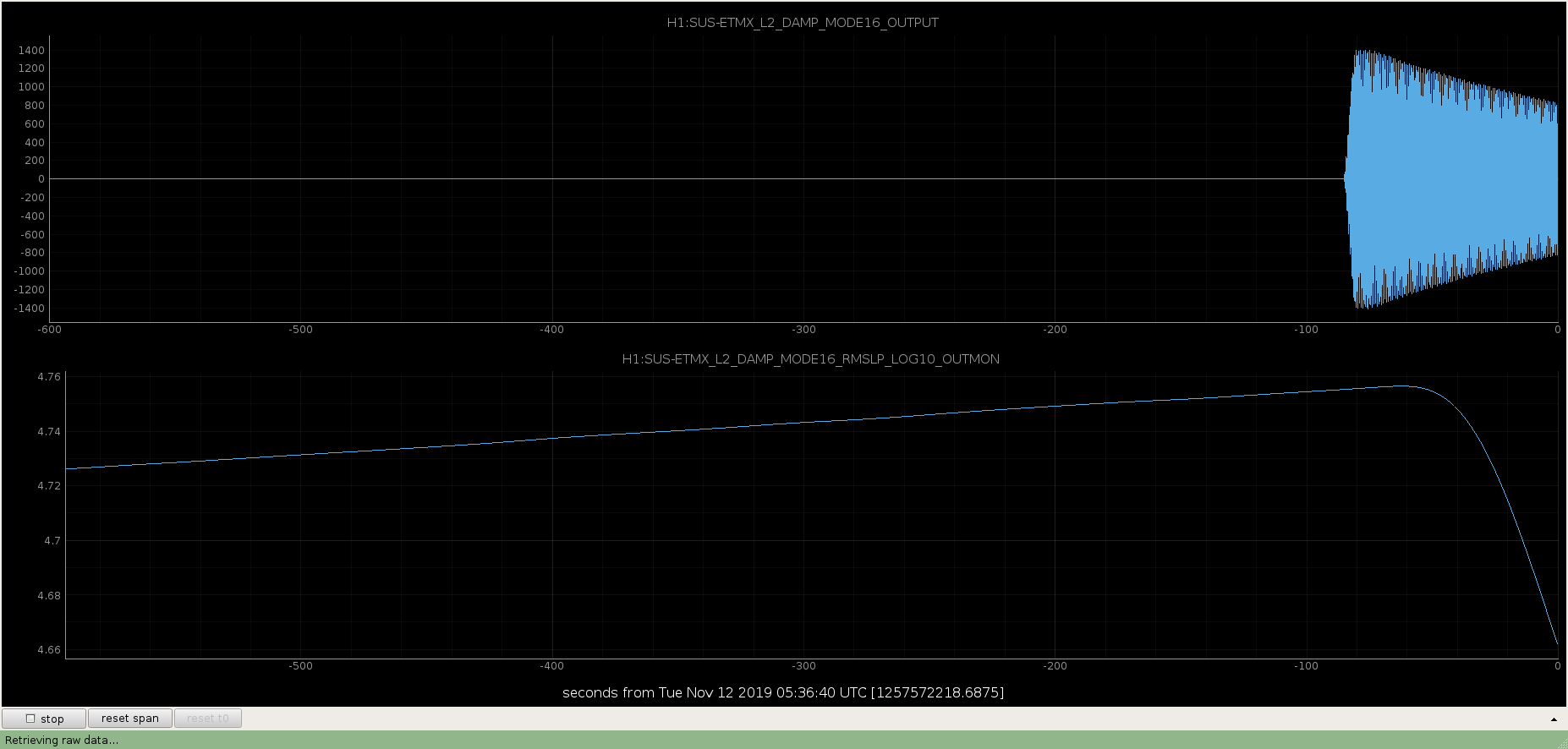
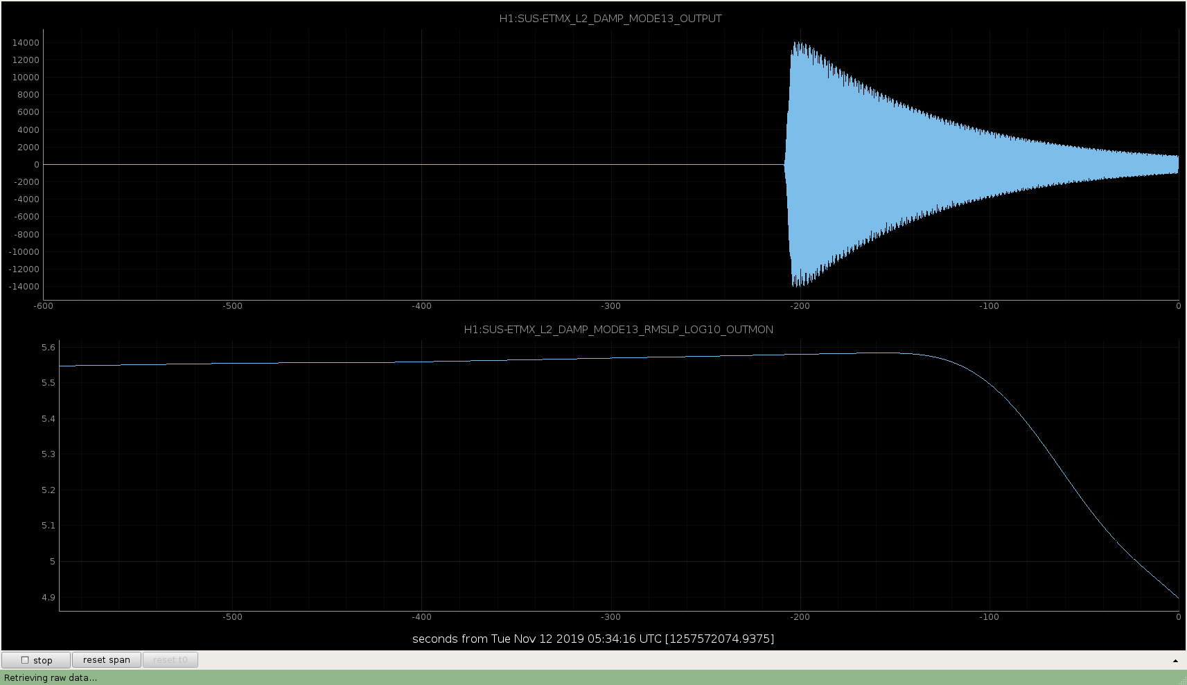
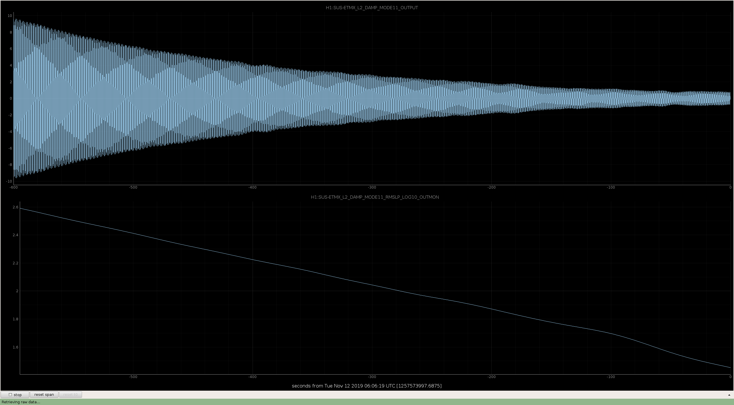
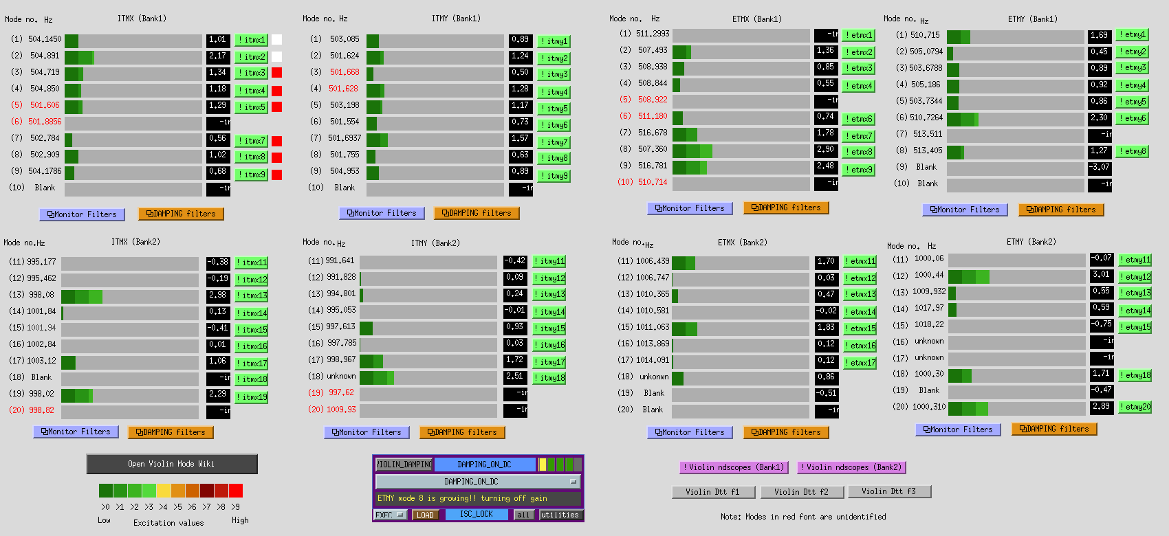
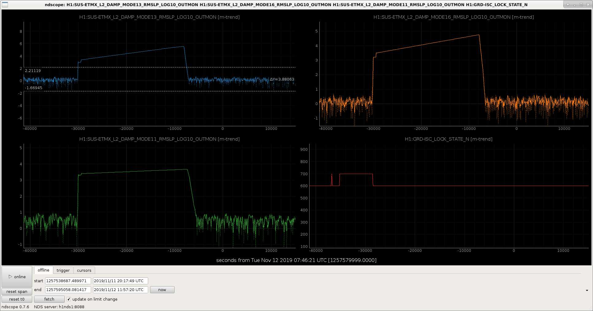
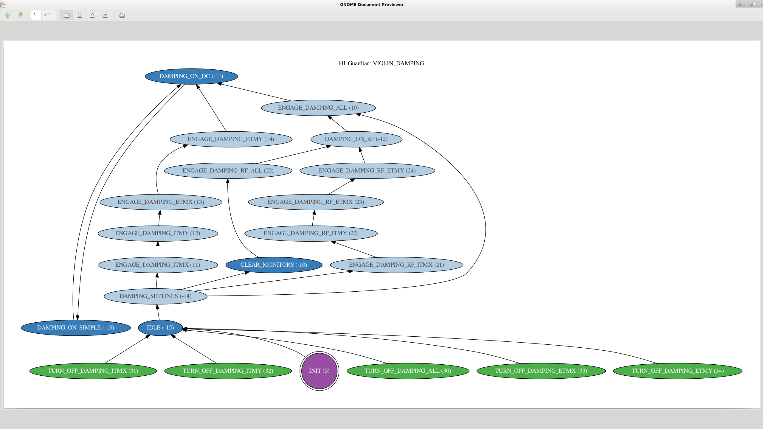
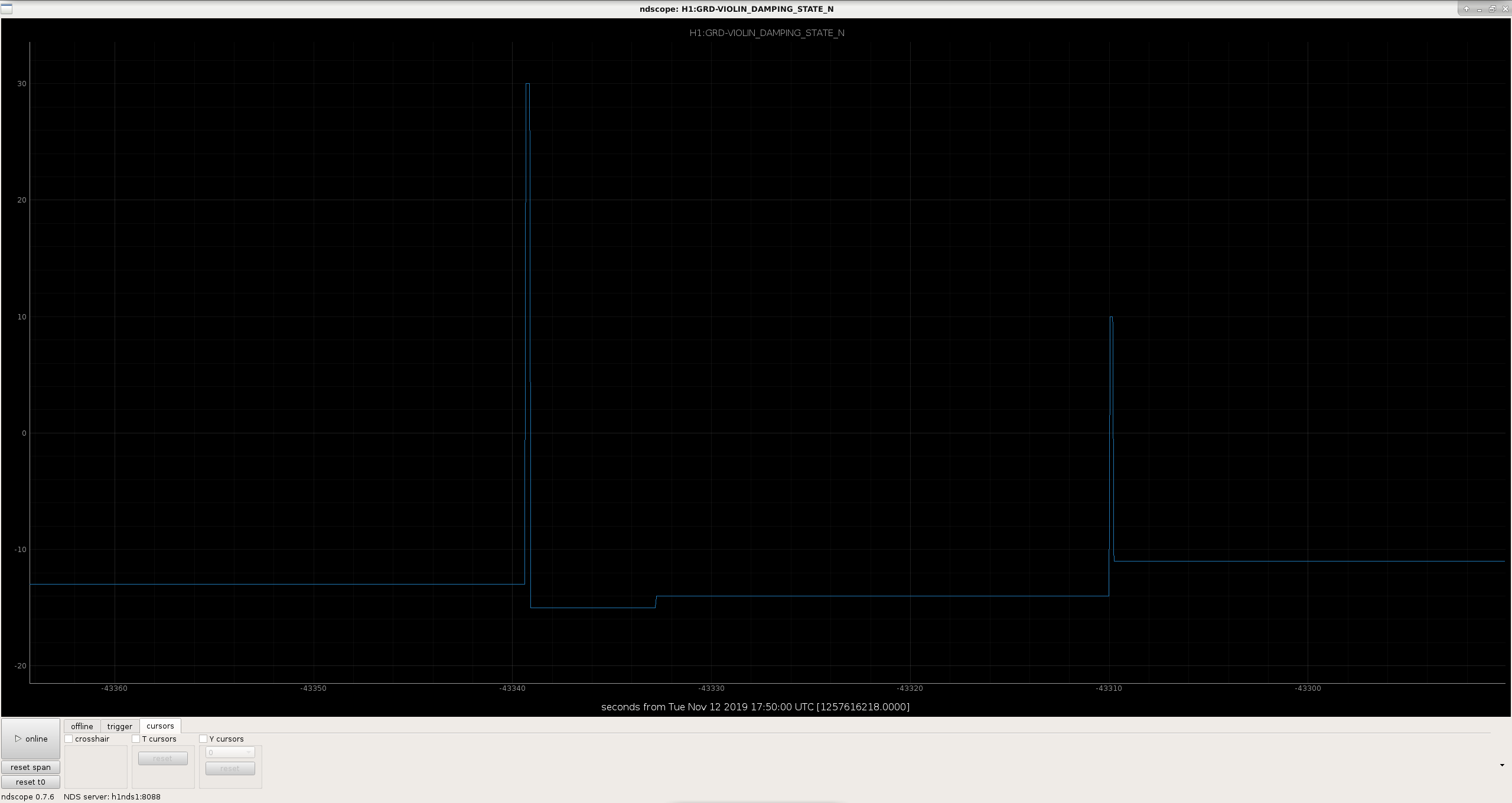
I had a look at the Guardian state when the damping was applied. It looks like it went from DAMPING_ON_SIMPLE (-13) to TURN_OFF_DAMPING_ALL state (30). The right way is to go from DAMPING_ON_SIMPLE (-13) to IDLE (-15) state and then to Damping_ON_DC (-11). This way Guardian is able to recollect the current status (else the information might be lost).
S. Dwyer, S. Karki, J. Kissel We gathered the full suite of calibration measurements today; measurement templates listed below. Analysis and commentary to come! We're at 38W of PSL input power (33.5 W input to PRM), SRCL offset is at 50 ct. DARM cavity pole (according to calibration line TDCFs) is 411 Hz. Sensing Function: 2019-11-11_H1_DARM_OLGTF_LF_SS_5to1100Hz_15min.xml 2019-11-11_H1_PCALX2DARMTF_LF_SS_5t1100Hz_10min.xml 2019-11-11_H1_PCALY2DARMTF_LF_SS_5t1100Hz_10min.xml 2019-11-11_H1_PCALX2DARMTF_BB_3min.xml 2019-11-11_H1_PCALY2DARMTF_BB_3min.xml Actuation function: 2019-11-11_H1SUSETMY_L1_iEXC2DARM_8min.xml 2019-11-11_H1SUSETMY_L1_PCAL2DARM_5min.xml 2019-11-11_H1SUSETMX_L1_TESTEXC_iEXC2DARM_5to100Hz_17min.xml 2019-11-11_H1SUSETMX_L2_iEXC2DARM_12min.xml 2019-11-11_H1SUSETMX_L2_PCAL2DARM_6min.xml 2019-11-11_H1SUSETMX_L3_iEXC2DARM_12min.xml 2019-11-11_H1SUSETMX_L3_PCAL2DARM_6min.xml
We did actuation measurement of the UIM stage to see if any angle to length coupling shows up in DARM. We measured the DARM signal by once driving through the L1 TEST that bypasses the drivealign filter bank and later through L1 CAL EXEC that goes through the drivealign filter bank. We didnot see any significant difference between the two measurements as shown in the plots attached below. Another null result but a step towards trying to understand the low frequency calibration.
The scripts used to analyze and generate these plots can be found here:
/ligo/svncommon/CalSVN/aligocalibration/trunk/Runs/O3/H1/Scripts/FullIFOActuationTFs/process_actuationmeas_UIM_DRIVEALIGN_20191111.py