Reminder that I have written a lock loss alerting program, which sends cell phone text messages to subscribers when H1 loses lock. Please contact me if you would like to be added to the subscribers list. You can turn your individual alerting on and off at any time.
[Gavin, Jenne, Timesh]
In preparation for conducting PI Q Measurements on the 13 kHz mode (IFO locking dependant) we added a 12 - 12.8 kHz & 12.8 - 13.8 kHz elliptical bandpass filters to H10MCPI_PI_DOWNCONV_DC8_INP [FM3, FM4], H1SUSETMYPI_ETMY_PI_DOWNCONC_DC7_INP [FM2, FM3] & H1SUSETMXPI_ETMX_PI_DOWNCONV_DC8_INP [FM1, FM2]. 12.8 - 13.8 kHz elliptical bandpass filters were also added to H1SUS_ETMSX_PI_UPCONV_UC8_SIG [FM6], H1SUS_ETMY_PI_UPCONV_UC7_SIG [FM3], H1SUS_ITMY_PI_UPCONV_UC8_SIG [FM5] & H1SUS_ITMX_PI_UPCONV_UC8_SIG [FM5].
In addition, to monitor the 13 kHz modes we added a cheby2 bandpass filter between 12.98 - 13.01 kHz to H1SUSPROCPI_PI_PROC_COMPUTE_MODE4_BP [FM2]. This should allow broad monitoring of the 13 kHz PI modes before each individual mode can be accurately determined. Additional broader filters may be needed.
Filter Parameters:
12 - 12.8 kHz - ellip("Bandpass", 4, 1, 40, 12000, 12800)
12.8 - 13.8 kHz - ellip("Bandpass", 4, 1, 40, 12800, 13800)
12.98 - 13.01 kHz - cheby2("Bandpass", 4, 40, 180, 200)
Unfortunately we never had time to conduct the measurements early this morning, but at least the filters are ready!
We've been having trouble the last few days / week with SRC align, particularly when the guardian thinks SRY is locked, then just rails the SRM, but still thinks that SRY is locked, so starts doing ASC things with nonsense error signals.
I've increased the thresholds for the trigger matrix. It looks at POPA DC, and the thresholds were 0.3, 0.25. The flashes regularly were going above 0.3, but the light level when the SRM is totally misaligned is about 0.28, so we weren't ever triggering off. I've changed it so that it turns on the SRCL trigger at 0.5 (nicely aligned the light level is about 0.6), and turns off the trigger at 0.3. With statistics of N=1, this seems okay.
Sheila (at JeffK's wise suggestion) also increased the watchdog trip levels for SRM's middle stage, since the SRM keeps tripping when we go to DOWN after this railing situation happens. We have now increased the threshold on the middle stage to match the lowest stage thresholds.
Since we're having trouble when hitting some of the smooth limiters when engaging ASC for full IFO, I have reduced the smoothing factor, which reduces the nonlinear region of the error signal. I think that it shouldn't really matter, since if you're on the rail and start coming off the rail, you're still heading toward zero. But, just in case, I've reduced the smoothing factor from 1.0 to 0.1. Rather than trying to explain in detail what that means, I refer back to the original post with some plots in alog 44261. In that alog, the first figure is what the smoothing will do with a value of 0.1 (our new val), and the third figure is what the smoothing was doing with a value of 1 (our old value).
Nutsinee, Daniel
When we remeasured the OPO length noise, we noticed that the second of our two peaks at 1 and 1.4kHz was gone. We traced this back to the maintenance day on 4/9/2019.
During this Tuesday we changed the laser current (alog 48361) and replaced a few pieces of electronics (alog 48353). At this point, I suspect the PZT driver.
I took another series of NLG measurements as a function of the (normalized) transmitted power from trans=0.3 to trans=1.78. Quickly before I leave I fixed offsets to improve the DB monitor diagnostic. I'll follow up with a table of the NLG measurements and the simulations for how the diagnostic monitor works but I don't have the time this morning. Now that the compression in the CLFPD RF has been fixed. The H1:SQZ-EST_RF6_NLG monitor should be quite reliable. I've checked that it is constant to 1% between 20uW and 120uW of CLF on the PD now that the offsets have been zeroed.
offsets zeroed at 0 power in:
CLF_REFL_LF, CLF_REFL_RF6 I and Q, and CLF_REFL_DC. and committed to SDF.
The DB's monitor in SQZ-EST_RF6_NLG has been calibrated at OPO Trans=1, NLG=3.23, corresponding to 8.28db (anti)squeezing generated. This is also Normalized NLG "x"-0.4435. There is a filter gain called NNLG2DBs that switches between the monitor reporting in DBs or NNLG "x". The monitor is more linear in the units of DB's, so that is what it is currently reporting (to be shown with the simulation).
DriptaB and RickS
This morning, we updated the Xend and Yend Pcal force coefficients for the Pcal power sensor readback signals.
We have decided not to continue with recording all the parameters that go into these force coefficients via the detailed force coefficient MEDM screens (which end up calculating the static force coefficients 16,000 times per second for the whole run) and instead just write the force coefficient into the records such asH1:CAL-PCALX_FORCE_COEFF_CTS2V_T and set the other record values such that their cumulative effect is just to multiply this coefficient by unity. We plan to update the MEDM screen and variable names ASAP.
The updated force coefficient files for LHO are in the SVN at:
/ligo/svncommon/CalSVN/aligocalibration/trunk/Runs/O3/H1/Results/CALCS_FE/lho_xend_pcal_epics_created-20191030.txt
/ligo/svncommon/CalSVN/aligocalibration/trunk/Runs/O3/H1/Results/CALCS_FE/lho_yend_pcal_epics_created-20191030.txt
and for LLO at:
/ligo/svncommon/CalSVN/aligocalibration/trunk/Runs/O3/L1/Results/CALCS_FE/lho_xend_pcal_epics_created-20191030.txt
/ligo/svncommon/CalSVN/aligocalibration/trunk/Runs/O3/L1/Results/CALCS_FE/lho_yend_pcal_epics_created-20191030.txt
The calculation of the force coefficients is performed in python code written by Ethan Payne. The parameters for the calculations and the resulting force coefficients are listed in the tables in the .pdf file in the comment attached below.
The force coefficients have changed from the values entered at the beginnign of the O3a run (on 20190401) by:
Xend Tx: +0.13%
Xend Rx: +0.29%
Yend Tx: +0.17%
Yend Rx: +0.27%
After updating the Pcal suspension filters (in, for instance H1:CAL-PCALX_TX_PD, hopefully later today) we expect the calibrated Pcal displacements to change by:
Xend Tx: +0.11%
Xend Rx: +0.27%
Yend Tx: +0.31%
Yend Rx: +0.42%
The force coefficients have changed mostly due to updated responsivity ratio estimates benefiting from additional measurments during the O3a run and inclusion of non-ideal ADC coversion factors.
The differences between the changes in force coefficients and the changes in the displacement coefficients is from discrepancies between the O2 ETM masses that have been used in the Pcal suspension filters and the O3 masses that should have been and will be implemented.
Note that these changes will not be fully realized until these filter files are updated.
The Epics records have been updated to the following values:
For Xend:
caput H1:CAL-PCALX_FORCE_COEFF_CTS2V_T 7.9278e-13
caput H1:CAL-PCALX_FORCE_COEFF_CTS2V_R 6.2344e-13
caput H1:CAL-PCALX_FORCE_COEFF_COS_THETA 0.5
caput H1:CAL-PCALX_FORCE_COEFF_RHO_G 1
caput H1:CAL-PCALX_FORCE_COEFF_ALPHA_W 1
caput H1:CAL-PCALX_FORCE_COEFF_ALPHA_T 1
caput H1:CAL-PCALX_FORCE_COEFF_ALPHA_R 1
caput H1:CAL-PCALX_FORCE_COEFF_GAIN_AA_R 299792458
caput H1:CAL-PCALX_FORCE_COEFF_GAIN_AA_T 299792458
caput H1:CAL-PCALX_OPT_EFF_TX2TM_INNER 1
caput H1:CAL-PCALX_OPT_EFF_TX2TM_OUTER 1
caput H1:CAL-PCALX_OPT_EFF_TM_INNER 1
caput H1:CAL-PCALX_OPT_EFF_TM_OUTER 1
caput H1:CAL-PCALX_OPT_EFF_TM2RX_INNER 1
caput H1:CAL-PCALX_OPT_EFF_TM2RX_OUTER 1
caput H1:CAL-PCALX_OPT_EFF_TOT_INNER 1
caput H1:CAL-PCALX_OPT_EFF_TOT_OUTER 1
For Yend:
caput H1:CAL-PCALY_FORCE_COEFF_CTS2V_T 9.2203e-13
caput H1:CAL-PCALY_FORCE_COEFF_CTS2V_R 6.2702e-13
caput H1:CAL-PCALY_FORCE_COEFF_COS_THETA 0.5
caput H1:CAL-PCALY_FORCE_COEFF_RHO_G 1
caput H1:CAL-PCALY_FORCE_COEFF_ALPHA_W 1
caput H1:CAL-PCALY_FORCE_COEFF_ALPHA_R 1
caput H1:CAL-PCALY_FORCE_COEFF_ALPHA_T 1
caput H1:CAL-PCALY_FORCE_COEFF_GAIN_AA_R 299792458
caput H1:CAL-PCALY_FORCE_COEFF_GAIN_AA_T 299792458
caput H1:CAL-PCALY_OPT_EFF_TX2TM_INNER 1
caput H1:CAL-PCALY_OPT_EFF_TX2TM_OUTER 1
caput H1:CAL-PCALY_OPT_EFF_TM_INNER 1
caput H1:CAL-PCALY_OPT_EFF_TM_OUTER 1
caput H1:CAL-PCALY_OPT_EFF_TM2RX_INNER 1
caput H1:CAL-PCALY_OPT_EFF_TM2RX_OUTER 1
caput H1:CAL-PCALY_OPT_EFF_TOT_INNER 1
caput H1:CAL-PCALY_OPT_EFF_TOT_OUTER 1
Tables of previous and updated force and displacement coefficients and O2 and O3 masses are in the attached .pdf file.
Talking with Rick further, the interpretation of the "change in calibrated displacement," which here I'll call xi is as follows:
[ NOW ]
xi = [ -------- - 1 ] * 100
[ EARLIER ]
where NOW is after today when the coefficients were installed (updated to be closer to the correct truth), and EARLIER is prior to today, during all of O3A (which therefore had a level systematic error proportional to xi).
I'll write a separate aLOG that combines this aLOG, the material in LHO aLOG 34153, and in T1900169 so that we understand exactly how this correction should be interpreted / displayed in terms of modifying previous reports of IFO response function uncertainty / systematic error, and what it means for h(t), and what it means for the BNS range.
TITLE: 10/31 Day Shift: 15:00-23:00 UTC (08:00-16:00 PST), all times posted in UTC
STATE of H1: Planned Engineering
OUTGOING OPERATOR: Ed
CURRENT ENVIRONMENT:
SEI_CONF state: WINDY
Wind: 4mph Gusts, 3mph 5min avg
Primary useism: 0.02 μm/s
Secondary useism: 0.26 μm/s
QUICK SUMMARY:
We are having issues in engaging ASC for full IFO. CHARD yaw starts off about -12000 each time we get there and we have to bring it in manually. After manually zeroing it and engaging a few seconds later we lose lock. So we are doing an initial alignment.
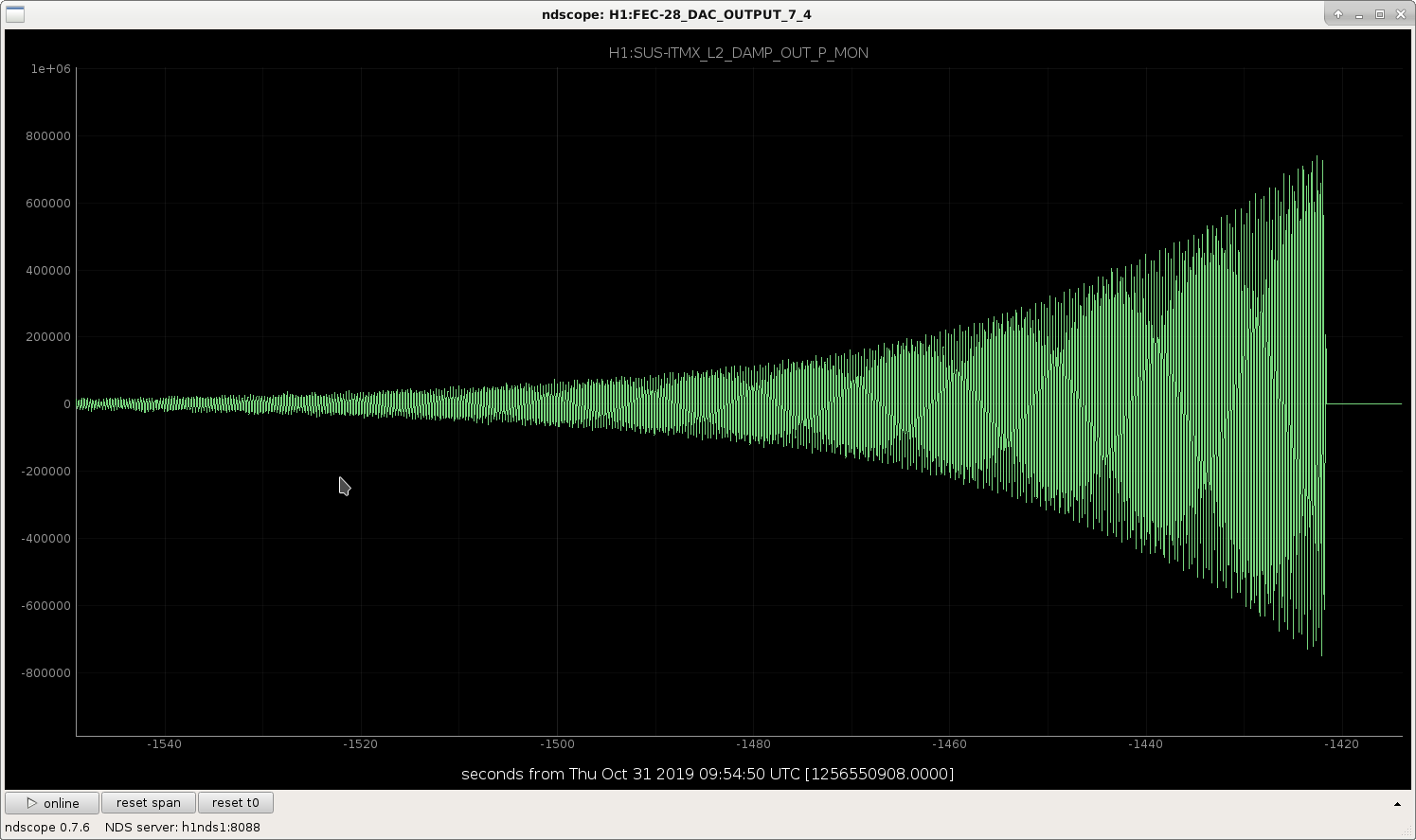
This last lockloss we were having the UL PUM coil watchdog trip on ITMX, the other quadrants seem fine. The violin damping channel H1:SUS-ITMX_L2_DAMP_OUT_P_MON is ringing up and looks to be causing this issue. Georgia's suspects mode 12.
We skipped ENGAGE_RF_VIOLINS, it lasted a bit longer but we still lost lock still during engaging ASC, not sure why.
The "ESD X driver is off" warning keeps repeatedly flashing up around CARM offset reduction and beyond, which is putting us all on edge.
We will leave it trying to lock, we're all going home.
I need to change the ESD test on DIAG_MAIN. I'll have a look at it shortly, but in the mean time note that it is only real if it stays up.
TL;DR we turned off the dang agilent and instantly got past DARM_TO_RF Long story is, we saw a ton of glitches in basically every PD at different levels of severity. One which saw bad glitches was AS_A RF45, which is what we use for control in DARM_TO_RF. A rouge commissioner who wanted to measure the IMC loop in full lock had left the Agilent plugged into the IMC servo board excitation port, causing some ground loop glitching throughout the racks, which translated to actual laser frequency glitching and optic motion which could not be handled in the DARM loop. The commissioner regrets the error.
Jonathan found that the new nuc0 was missing the cronjob to periodically generate the ecp_cookie needed to get the L1 range from the LLO DMT. We were also missing the environment variable defining the cookie's location.
There is coherence between HAM2 and DARM, it seems possible that this is because of clipping on the ISS 2nd loop array, as solved in 46412. The attached plot shows this.
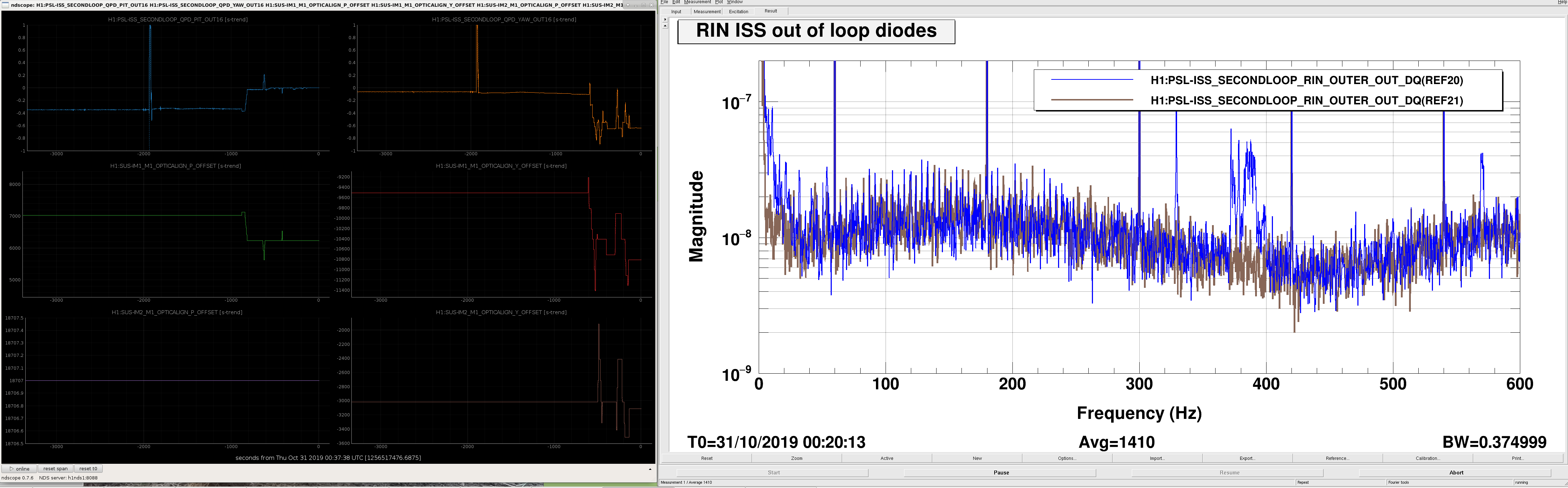
Since I don't know how to distinguish between clipping on the ISS path after transmitting through IM4 and clipping through the input Faraday without picoing the ISS path, I instead moved IM1 and IM2 a bit until these peaks went away and we were more centered on the ISS QPD (at least in pitch.... we might need to pico for yaw if this IM1, IM2 position is better overall for the IFO).
Since we lost lock, I took the opportunity to move things around. I had IMC-only, with 30W injected, and closed the ISS second loop by requesting ISS_ON of the IMC guardian. The blue spectrum is the RIN of the out of loop PD before I moved anything, and brown is after. The peaks around 400Hz are gone, as is a bit of noise at low frequency, and another peak around 575Hz. The ndscope shows the ISS QPD spot, and the IM1 and IM2 sliders.
Gavin and I are running through an initial alignment before trying to relock.
It occured to me that I ought to have used IM3 and IM4 to compensate for the IM1,IM2 move earlier, rather than using PR2 and IM4. So, since I'm not succeeding at acuiring lock (although as this earthquake rings down, I'm getting further each attempt), I undid PR2's moves from the earlier initial alignment and zeroed the INP error signals instead using IM3 and IM4 with Xarm IR locked. Now I'm finishing up the rest of initial alignment, and hopefully the earth will have quited down enough for locking.
Hmmm. No good. We can't get through the CARM offset reduction sequence with this alignment. We've had similar problems in the past, where if we move the IMs, we can't quite compensate and get back the exact same input alignment, and then can't get through CARM reduction. The reliable solution in the past has been to revert the IM alignment, which I have now done. We'll need to pico the ISS to get rid of the peaks.
I've moved picomotor PM1 on HAM2 to reduce the peaks in the ISS out of loop diodes. In the attached spectrum, blue is before the move (after reverting the IMs), and brown is after moving the pico. I didn't try moving PM5, since the January alog from Georgia indicated that PM1 is the one that was most effective last time. Centering the beam on the QPD did not reduce the peaks - notice in the ndscope top right that the yaw is (as was true after the IM move) now farther from center. But, this is what makes the peaks go away, so it's what we'll try.
Nope, we've lost lock at the same DARM_TO_RF area again. Georgia and folks are going to keep having a look.
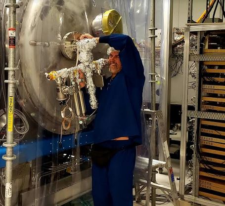
Kyle prepared a new Prisma Plus RGA for HAM6 chamber by baking it remotely prior to installation during Oct. vent. Background is pristine and includes a 10 l/s ion pump to preserve vacuum during chamber vents and also two calibration gas bottles.
Yesterday we had a chance to finally scan HAM6 chamber at total pressure of 9e-7 Torr. RGA was in SEM mode and filament was warmed up for several hours. Scan attached.
Note that the RGA assembly's 10 l/s ion pump is on (using as interium pressure gauge while PT110 is offline) here and has a comparable net pump speed as the conductance to HAM6. As such, a factor of ~2 bias exists. If it were off, as would be nominally the case, the peaks would be ~twice as large as shown.
Attached the quick OPO in-loop measurement from January and now (October). Not sure what's going on with the overall higher noise. It's likely that I don't know the old calibration all that well.