Displaying reports 37861-37880 of 89075.Go to page Start 1890 1891 1892 1893 1894 1895 1896 1897 1898 End
Reports until 14:57, Tuesday 29 October 2019
LHO VE
kyle.ryan@LIGO.ORG - posted 14:57, Tuesday 29 October 2019 - last comment - 15:31, Tuesday 29 October 2019(52775)
Interium solution for HAM6's high voltage protection pressure interlock - using 10 L/s ion pump as a defacto pressure gauge

Fil C., Richard M., Kyle R.

We are temporarily utilizing a contact closure provided by the 10 L/s ion pump controller (local to the newly installed RGA assembly) as an interium solution for the high voltage pressure interlock in HAM6.  Normally, this contact closure is provided by PT110.  However, PT110 is out of service until further notice. 

Details:

It was noted, while PT110 was still working, that an indicated pressure of 9 x 10⁻⁷ torr given by PT110 corresponded to a pump current-converted pressure of 4 x 10⁻⁷ torr at the 10 L/s ion pump.  9/4 = 2.25:1 ratio.  This is as expected due to the conductances resulting from the physical configuration.  As such, I programmed the 10 L/s ion pump controller's relay contact (P1 pins 10 and 12) to open for any pump current-converted pressures exceeding 1 x 10⁻⁶ torr.  This value, (1 x 10⁻⁶ torr) x (2.25) ~ 2 x 10⁻⁶ torr, is ~ 1/5 the nominal interlock setpoint of 1 x 10⁻⁵ torr, i.e., we are now expecting a safety margin of 5 for this unproven setup. 

While not able to test this setup using actual measured pressure changes, I was able to simulate the functionality via programming the setpoint below and above the measured current-converted pressure and observe the as expected behavior from the relay contact using an ohm meter.


Comments related to this report
kyle.ryan@LIGO.ORG - 15:31, Tuesday 29 October 2019 (52777)

Fil C. fabricated, on short notice, the custom cable that interfaced the ion pump controller to the existing CDS cable. 

LHO VE
david.barker@LIGO.ORG - posted 14:49, Tuesday 29 October 2019 (52773)
Vacuum alarms update

Following discussion with Chandra and Richard, I've bypassed the HAM6 vacuum alarm (PT110) for a week

Tue Nov  5 13:29:40 PST 2019
For channel(s):
    H0:VAC-LX_Y0_PT110_MOD1_PRESS_TORR


I removed the temporary increments in alarm levels now the main vacuum system is nominal

PT124 from 7.0e-09 to 5.0e-09

PT114 from 5.0e-08 to 5.0e-09

Alarm system was restarted to take these changes.


LHO VE (CDS)
chandra.romel@LIGO.ORG - posted 14:25, Tuesday 29 October 2019 (52771)
PT-110 pressure gauge on HAM6 faulty

In an attempt to fix the noisy/spiky gauge on HAM6, it appears the one and only hot cathode filament is not working. Yesterday we degassed the filament but readback was still noisy, and randomly spikes above in-chamber high voltage set point of 1e-5 Torr, causing HAM6 shutter to depower. Today I replaced the electronics with a set from brand new gauge but the gauge would not read beyond e-2 Torr and emissions command gave an error. It appears that the filament has failed. Waiting for response from manufacturer. Gauge is Inficon BCG450-SE, Bayard-Alpert Pirani Capacitance Diaphragm style. 

Meanwhile, Kyle and Fil found a work around and are currently interlocking pressure for HV trip from the readout of 10 l/s ion pump recently installed on new HAM6 RGA manifold.

H1 TCS (OpsInfo)
richard.mccarthy@LIGO.ORG - posted 13:50, Tuesday 29 October 2019 (52770)
H1:TCS-ETMY_HWS_SLEDSHUTDOWN Nomenclature

For now and for the forseeable future, H1:TCS-ETMY_HWS_SLEDSHUTDOWN will read opposite of its normal operating values.

In other words: OFF = On and ON = Off

This will be reflected in the DIAG_MAIN notification as well. So when in doubt, trust DIAG_MAIN or ask me.

H1 General
yannick.lecoeuche@LIGO.ORG - posted 12:57, Tuesday 29 October 2019 (52769)
LVEA transitioned to Laser Hazard

TJ transitioned the LVEA to laser hazard

H1 CDS (DAQ)
david.barker@LIGO.ORG - posted 12:51, Tuesday 29 October 2019 - last comment - 16:24, Tuesday 29 October 2019(52768)
CDS Maintenance Summary, Tuesday 29th October 2019

NCAL fast channel

Timesh, Jeff, Dave:

h1calex was modified to add a NCAL_MASTER NCALX part. This reads adc0_24 as the H1:CAL-NCALX_ENCODER_VELOCITY_OUT_DQ fast channel. A DAQ restart was required.

SEI and SUS model changes

Jenne, Jim, Chiara, Dave:

The models h1susbs, h1susprm, h1sussrm, h1seiproc, h1isietmx and h1isietmy were restarted. A DAQ restart was required.

DAQ Restart

Dave

at 12:05 PDT I restarted the DAQ for the above model changes. There were no problems with the restart, h1nds1 did not encounter any of last week's problems.


Comments related to this report
david.barker@LIGO.ORG - 14:31, Tuesday 29 October 2019 (52772)

CDS maintenance part deux:

Installed latest BRS and Guardian INI files into H1EDC. Increased data rate of NCAL ROTATION_VELOCITY channel from 1024 to 4096 Hz. Restarted h1calex and DAQ.

david.barker@LIGO.ORG - 14:58, Tuesday 29 October 2019 (52776)

I have patched and restarted all the Debian9 nucs in the control room. When nuc21 came back online is found that h1pslcam1 was not responsive.

I verified that this camera cannot be pinged or accessed over the network. I'll leave the blank window on the nuc display as a reminder that we need to check this camera on the next visit to the PSL enclosure.

david.barker@LIGO.ORG - 16:24, Tuesday 29 October 2019 (52782)

Daniel found Beckhoff SDF for PLC4 was frozen, I restarted h1sysecatc1plc4sdf on h1ecatmon0.

H1 CAL
yannick.lecoeuche@LIGO.ORG - posted 12:35, Tuesday 29 October 2019 (52767)
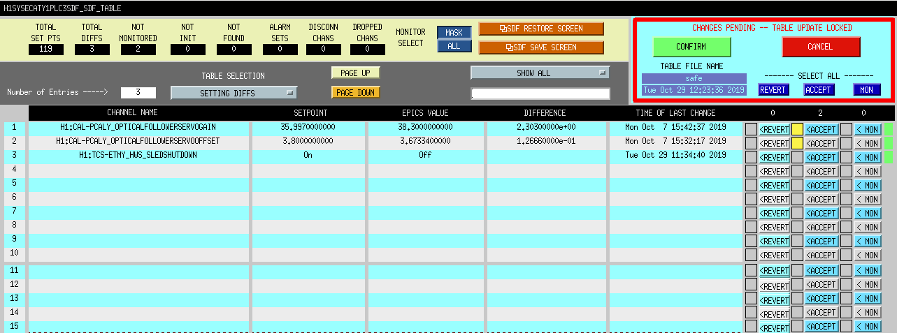
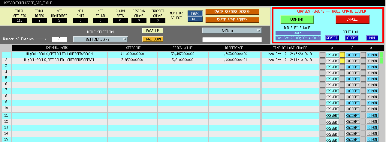
Accepting Pcal EX/EY OFS gain and offset sdf diffs

Accepting sdf diffs for EX/EY OFS gain and offset changes that were made as part of transmitter module maintenance performed on 10/07 (see alog 52334).

Images attached to this report
H1 AOS (CAL, CDS, SUS)
vladimir.bossilkov@LIGO.ORG - posted 11:33, Tuesday 29 October 2019 (52765)
Testing foton.py ZPK importing a susmodel

Vlad

Continuing from conclusion of previous aLOG.

It looked like foton.py is importing filters correctly with minimal error, and should be able to import data from a complete susmodel. Here I discuss issues that arose when I tried to do this.

Relevant gds svn subdirectories for source code to which I refer throughout:

I attempted to plot the zpk data of the O2 susmodel with Python:

I attempted to plot the zpk data  of the O2 susmodel with Matlab:

Issues I encountered with foton.py:

In summary two issues:

I did the same changes as I made in Python through Matlab, to see how different the TF looks when I remove the positive poles, and it is definitely not the same thing.

For the time being, one still needs to use quack to import the susmodels.

Non-image files attached to this report
H1 SQZ (SQZ)
lee.mcculler@LIGO.ORG - posted 11:32, Tuesday 29 October 2019 (52762)
High CLF squeezing tests with Homodyne

Yesterday Kentaro and I took squeezing measurements in the homodyne at various CLF levels with the ISS's running. The homodyne should still have the high ~.98 visibility established Sunday by Nutsinee and Kentaro. This was taken with NLG=5.91 (OPO Trans monitor 1.8x), corresponding to 11.74db of generated antisqueezing.

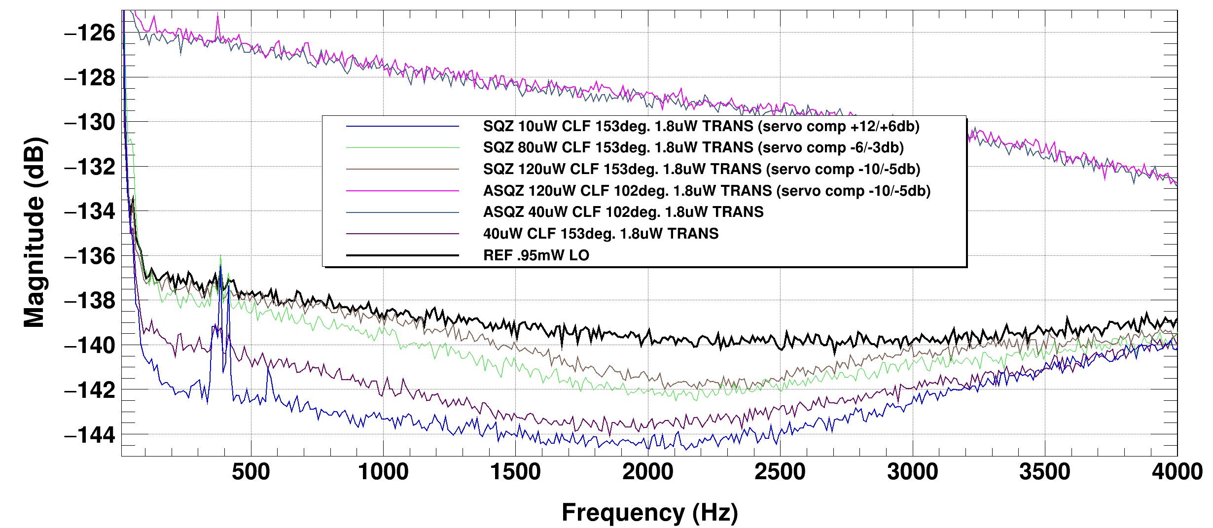
HD_SQZ_vs_CLF.png

shows the various squeezing spectra and references up to 4kHz. You can see immediately that the reference isn't flat. The compensation filters aren't shaped quite right. The noise becomes worse at high frequencies due to rolloff of the whitening and relative increase in bit-noise (see D1700403). We could potentially increase the gain of those boards (or downstream?) to help with that, although improving the homodyne isn't too essential.

At around 2kHz you can see we can see ~4-5 db squeezing. There is some additional noise at low frequencies which is dependent on the CLF power level. This is alarming if it is also affecting the interferometer squeezing. At the higher CLF powers, it eliminates the gains from squeezing. Interestingly, it does not degrade the antisqueezing spectrum, illuminating some mechanisms. Since it only affects squeezing, it could potentially be CLF-level dependent phase-noise, but the SQZ spectrum has shape and phase noise will (almost) always create a broadband degradation to squeezing. For this reason we suspected noise sidebands on seeding, which would indeed have both a frequency and CLF-level dependence.

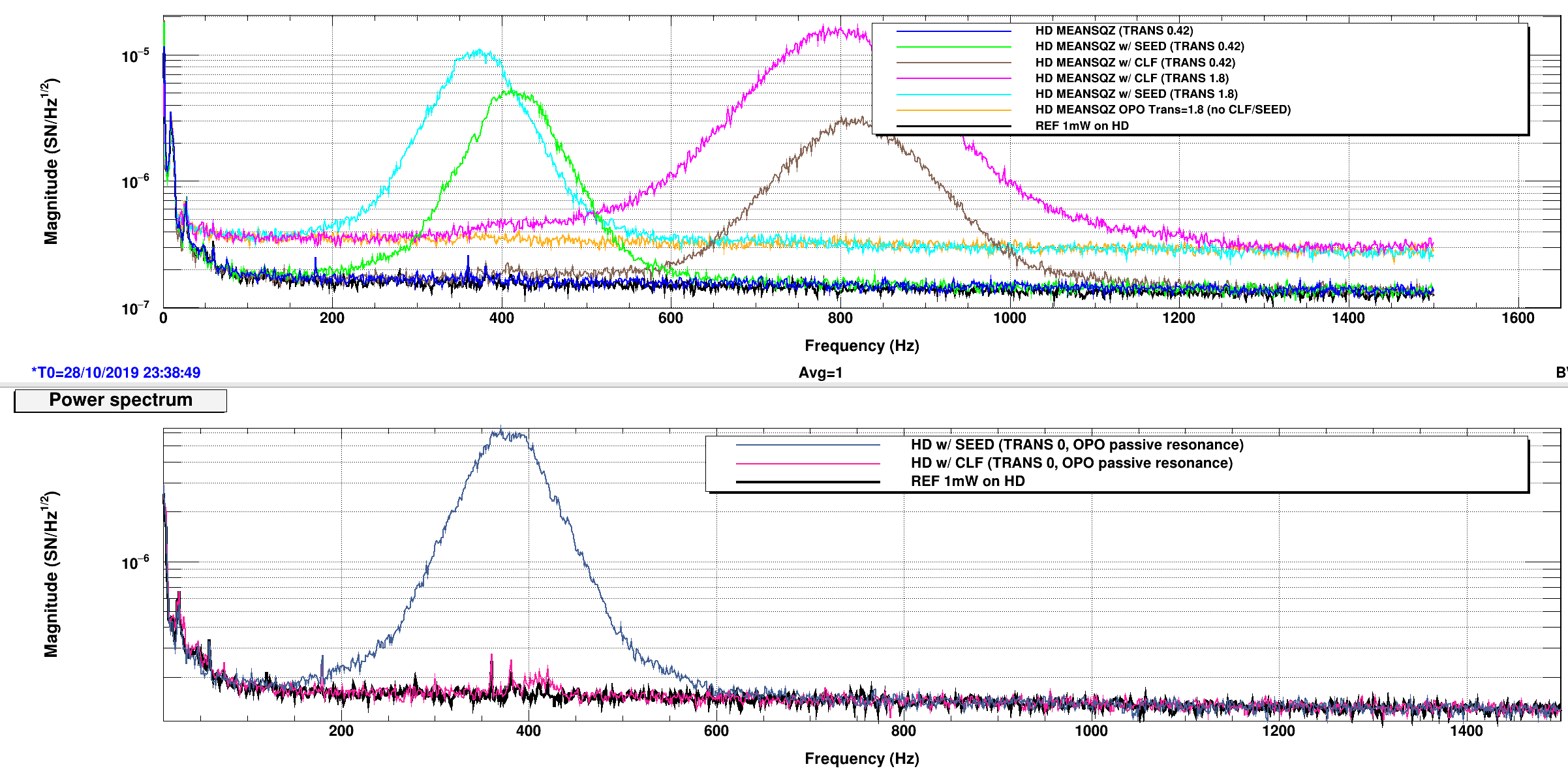
From here we switched operating modes. After the ALS fiber pickoff point and AOM frequency adjustment to stable 80MHz, the SQZ laser can be stably offset in frequency to the PSL. This allows us to shift the LO frequency w.r.t the squeezer carrier and seeding, to look for beatnotes. The LO loop was unlocked, and the VCO was shifted by 200Hz, creating a 400Hz offset of seed light and LO. Any seeding should create a 400Hz noise peak on the homodyne. The total integrated noise power excess over shot-noise indicates the total power in the seeding.

HD_SEEDING.png shows the studies here.

The main curves to look at are to compare the w/ SEED and w/CLF. The w/ SEED curves show the homodyne with the CLF fully blocked, and the SEED semi-blocked (unblocked flipper, but leaking through the fiber-switch). This can purely generate the 400Hz peak and serves as a good reference, especially given the very strange 800Hz harmonic peak caused by the CLF light.

The CLF seeding curves are generated with the CLF having 40uW on OPO-M2, held to that level by the CLF-ISS from a maximum of 70uW given the picomotor settings.

The further studies show that the CLF 800Hz peak depends on the nonlinear gain. The OPO power was decreased to .42x on transmission. This reduced the seed and CLF levels. The SEED level dimished because the seeding light should be scaled approximately by the NLG. The CLF noise level scaled by more than the true seeding. Furthermore, in the bottom plots, the OPO pump was zerod, and the OPO was manually moved on resonance (it is extremely stable, and holds for a while). The resonace was checked by maximizing the LO-CLF beatnote level while the CLF was on. During this mode, the w/SEED still shows a similar level of true seeding, but the w/CLF shows no 800Hz peak, and only a small excess of true seeding at 400Hz, so indeed the CLF has very little (few attowatts) of actually seed light in this configuration. The missing 800Hz during 0NLG shows the dependence on parametric gain of the CLF noise mechanism.


It is very difficult for the OPO to generate 800Hz in any optical manner, since the pump/parametric gain frequency is matched to the seed/CLF, nothing in the OPO "has knowledge" of the 400Hz offset, only the LO light carries the 400Hz offset. To generate 800Hz, there must be some nonlinearity in the homodyne. My theory is that the RF level of the CLF should be oscillating at the 800Hz. The RF level depends on the squeezing angle due to the unbalanced CLF sidebands. The 400Hz LO-offset then has the squeezing ellipse rotating at 400Hz, and there is a similar ellipse determining the CLF3 sideband level and phasing (it is offset from the sqz ellipse ~20deg due to the 3.125MHz and OPO bandwidth). With the ellipses spinning, the RF level then gets doubled from the mirror symmetry of the ellipse. I think the noise peak is from finite power supply rejection and the oscillating RF power.

This means that the homodyne electronics could probably be improved. It also means that the degradation should likely be coherent with the RF3-Q signal. We will look today once the squeezer is back (some high-voltage for PZTs is down at the moment).

For the interferometer this may or may not have implications. The RF gain of the OMCPDs is smaller and the electronics diffferent, so difficult to predict. The OMC lowers the CLF power to 1%, but the carrier is 20x the homodyne. In the past, we have characterized the frequency-doubled peak as OPO conversion of optical backscatter (unique to IFO compared to homodyne, which has much lower backscatter). If this mechanism is present on OMCPDs, then we may have to revise backscatter measurements. Once we have IFO time, we can enable/disable the CLF and perform the same test as here with the IFO to check.

 

Images attached to this report
H1 PEM
jeffrey.bartlett@LIGO.ORG - posted 11:10, Tuesday 29 October 2019 (52764)
Bi-Monthly Dust Monirot Vacuum Pump Checks (FAMIS #12999)
   Made small adjustments to all three dust monitor vacuum pump air bypass to bring the pressure back to 18inHg. 
   The temperatures on all three pumps are lower, due to current colder outside temperatures.  
   All three filters/mufflers were clean of carbon dust. 

   All looking good at this time. 

Closing FAMIS #12999 
H1 PSL
jason.oberling@LIGO.ORG - posted 11:08, Tuesday 29 October 2019 - last comment - 11:18, Tuesday 29 October 2019(52763)
PSL PMC/RefCav Beam Alignment Tweak and Power Watchdog Reset (FAMIS 10734)

In advance of the imminent start of O3b, I have tweaked the beam alignment into both the PMC and FSS RefCav.  All tweaking was done with the ISS OFF.

After turning the ISS back on, I noticed the % diffracted power was down around 1.4%; this is below our 2% minimum, so I adjusted the ISS Ref Signal from -2.01V to -2.0V, which brought the % diffracted power back up to ~2%.  This change was accepted in both the safe.snap and OBSERVE.snap SDF files.  With the ISS back ON the PMC is now transmitting 53.3 W.

I also reset both PSL power watchdogs at 18:05 UTC (11:05 PDT).  This completes FAMIS 10734.

Comments related to this report
jason.oberling@LIGO.ORG - 11:18, Tuesday 29 October 2019 (52766)

In addition to the above, while resetting the PSL power watchdogs the PSL Beckhoff Status screen was showing a 'Check Diode Chiller' warning.  Heeding said warning, I checked on the diode chiller; it was showing a 'Low Water Level' warning, which went away while I was taking the cap off of the reservoir (this is an indication that the chiller is right on the edge of being low on water; the timing with me removing the cap was coincidence).  I added 500mL of water to the diode chiller and did not observe the low water level warning again.

H1 General
yannick.lecoeuche@LIGO.ORG - posted 08:03, Tuesday 29 October 2019 (52761)
Ops Day Shift Transition

Ops Shift Transition: 10/29/2019, Day Shift 15:00 – 23:00 (08:00-16:00) - UTC (PT)

State of H1: Planned Engineering

Intent Bit: Commissioning

Weather: 0-10 mph wind

Primary 0.03 – 0.1Hz: 0.01 um/s

Secondary 0.1 – 0.3Hz: 0.15 um/s

Outgoing Operator: None

Quick Summary: Tuesday maintenance ongoing

H1 AOS
daniel.brown@LIGO.ORG - posted 03:35, Tuesday 29 October 2019 (52759)
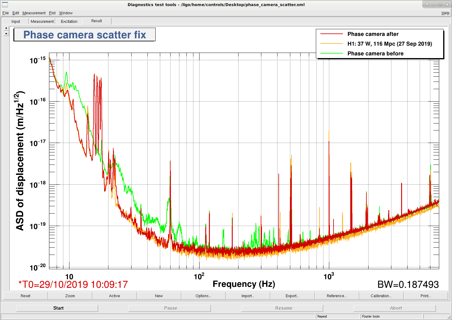
Phase camera scattered light fixed

Cao, Dan

After getting to NLN we found the phase camera path was causing a lot of scattering issues. Tonight we think we have fixed all or most of it. The main issue was that the realignment of the interferometer caused the POP beam to fall off of the 1811 we are using, this was scattering all over the table and caused all the low frequency scatter. The smaller lines around 300Hz were from a lens I hadn't screwed down. Additionally we installed a 90:10 beamsplitter to dump most of the POP light into the black glass beam dump, as at full power there is way too much for the camera anyway. We borrowed a flip mirror from the TCS cupboard that we can drive with a 5V signal to dump the rest of the path after the beamsplitter if any new issues arise, although we will have to sort out a channel for it tomorrow.

As it looks much better I have left the phase camera path open and maybe some shaking tests will get done tomorrow.

Leaving for the night, IFO is locked in nominal low noise.

Images attached to this report
H1 ISC (ISC)
craig.cahillane@LIGO.ORG - posted 01:58, Tuesday 29 October 2019 - last comment - 03:36, Tuesday 29 October 2019(52757)
Injections for later tonight
I was able to get a first pass CARM OLG + REFL A+B time series at the PSL racks.
Dan and Cao are still at ISCT1 mitigating scatter peaks from the phase camera setup.

If possible, could the phase camera team please run the following scripts on workstation zotws17, workspace 8:

python /ligo/home/craig.cahillane/Git/IFO/general/scripts/Intensity_noise_injection_caller.py

then

python /ligo/home/craig.cahillane/Git/IFO/general/scripts/Frequency_noise_injection_caller.py
Comments related to this report
daniel.brown@LIGO.ORG - 03:36, Tuesday 29 October 2019 (52760)

Intensity injection had an error, but the frequency one ran.

H1 CAL (CAL)
timesh.mistry@LIGO.ORG - posted 20:46, Monday 28 October 2019 - last comment - 13:52, Monday 04 November 2019(52751)
DARM Anti-Spring is Back!

[Sheila, Craig, Timesh]

Cal SVN root: /ligo/svncommon/CalSVN/aligocalibration/trunk

This morning, Sheila took the usual sweep of measurements for calibration at around 15:56:49 UTC. When looking at the results from the processing sensing script, we see an antispring at f_s = 4 Hz. Attached to this alog is the raw data, the MCMC model with the measurement, the reference model with all the measurements and MCMC corner plot of this measurement.

We tried to re-measure the the Open Loop Gain (OLG) at around 01:10:13 UTC during which, the PCAL measurement ran successfully however the OLG measurement failed due to an earthquake. Before re-running the measurement we set H1:LSC-SRCL1_OFFSET from 100.0 counts to 0.0 counts. The steps in offset was to make sure that there was not a large loss of power in the arms and have the ability to quickly restore the IFO if required. The motivation for changing the offset was that in O3a, a value of 100.0 counts was used to compensate for a pro-spring (for example, see LHO alog 51440 and comment therein) and since we are measuring an anti-spring with the same counts offset, we may have been driving an anti-spring. The hypothesis is that by removing the offset, the spring would tend towards zero.

We were able to collect OLG data from 1083.7Hz down to 10.334Hz before the lockloss. This is not sufficient for re-measuring the spring/anti-spring of the IFO thus, we will attempt to repeat the OLG measurement once the IFO is back into nominal low noise (NLN) and has thermally equilibrated. The dtt files and processing scripts that were used are given below for the original measurements and the re-run measurements (svn revision given in brackets):

Measurements

Sensing:
^/Runs/O3/H1/Measurements/FullIFOSensingTFs2019-10-28_H1_DARM_OLGTF_LF_SS_5to1100Hz_15min.xml    (r8632)
^/Runs/O3/H1/Measurements/FullIFOSensingTFs2019-10-28_H1_PCALY2DARMTF_LF_SS_5t1100Hz_10min.xml    (r8632)

^/Runs/O3/H1/Measurements/FullIFOSensingTFs2019-10-28a_H1_DARM_OLGTF_LF_SS_5to1100Hz_15min.xml    (r8632)
^/Runs/O3/H1/Measurements/FullIFOSensingTFs2019-10-28a_H1_PCALY2DARMTF_LF_SS_5t1100Hz_10min.xml    (r8632)


Actuation:
^/Runs/O3/H1/Measurements/FullIFOActuationTFs/2019-10-28_H1SUSETMX_L1_iEXC2DARM_10min.xml    (r8632)
^/Runs/O3/H1/Measurements/FullIFOActuationTFs/2019-10-28_H1SUSETMX_L1_PCAL2DARM_8min.xml    (r8632)
^/Runs/O3/H1/Measurements/FullIFOActuationTFs/2019-10-28_H1SUSETMX_L2_iEXC2DARM_12min.xml    (r8632)
^/Runs/O3/H1/Measurements/FullIFOActuationTFs/2019-10-28_H1SUSETMX_L2_PCAL2DARM_6min.xml    (r8632)
^/Runs/O3/H1/Measurements/FullIFOActuationTFs/2019-10-28_H1SUSETMX_L3_iEXC2DARM_12min.xml    (r8632)
^/Runs/O3/H1/Measurements/FullIFOActuationTFs/2019-10-28_H1SUSETMX_L3_PCAL2DARM_6min.xml    (r8632)

Processing

Sensing:
Reference model: modelparams_H1_20190909
^/Runs/O3/H1/Scripts/FullIFOSensingTFs/process_sensingmeas_20191028.py    (r8636)

Actuation:
Reference model: modelparams_H1_20190416
^/Runs/O3/H1/Scripts/FullIFOSensingTFs/process_actuationmeas_20191028.py    (r8637)


Non-image files attached to this report
Comments related to this report
timesh.mistry@LIGO.ORG - 12:22, Tuesday 29 October 2019 (52756)

[Craig, Timesh]

We re-measured the sensing by re-measuring the OLG and PCALY. Before re-running the measurement we set H1:LSC-SRCL1_OFFSET from 100.0 counts to 0.0 counts.  The Earth stayed quiet enough that we now see a ~9Hz pro-spring after the successfully completion of both measurements. Once again the raw data, the MCMC model with the measurement, the reference model with all the measurements and MCMC corner plot of this measurement are attached to this alog.

I am uncertain what the reason is, or the cause of, the pro-spring/anti-spring in these scenarios.

Non-image files attached to this comment
jeffrey.kissel@LIGO.ORG - 19:46, Tuesday 29 October 2019 (52787)
I'm not confident that the above 0ct SRCL offset data is really a "9 Hz pro spring," and Sheila and I are not so confident it's really bad just yet. (Where "bad" would be "enough of a low frequency response that would drive us to change the sensing function model in the front-end.")

I've compared the above two data sets against the last few data sets of O3A in the attachment below.

One can see that, although, indeed a 100 ct SRCL offset is an anti-spring, the 0 ct offset data residual looks much like the subtle residual mixing of a detuned SRC and some sort of L2A2L crosscoupling (or whatever label you want to put on the as-of-still-poorly-understood low frequency response that's *not* a detunement of the SRC) that we saw at the tail end of O3A *after* installing the 100 ct offset.

Also note that there's no magic to the numbers here: they're all determined by "quick" tests -- easy changes in the IFO configuration that need confirming with ~25 minutes of measurement. We started with no digitally requested offset (0 ct) for most of O3A, and then on one Wednesday after sorting out our August spot position kerfuffle, we tried 100 ct, then 200 ct to try to reduce the severe pro-spring with which we ended up. 200 ct seemed unstable, and 100 ct conveniently seemed to give us the "no detuning" response we wanted. Now, the quick test was "turn it off," and *that* got us close enough, so we're running with that for now. Sadly, we've yet to put together a model that's complete enough to help us understand and/or predict what's going on.

So, for now, if we can get the IFO stable enough for us to have the patience to do some more exploring, we'll measure the sensing function again to make sure this new answer -- with 0 ct SRCL offset -- is consistent, or if the resulting low frequency response moves around with time.
 
Non-image files attached to this comment
jeffrey.kissel@LIGO.ORG - 13:52, Monday 04 November 2019 (52973)
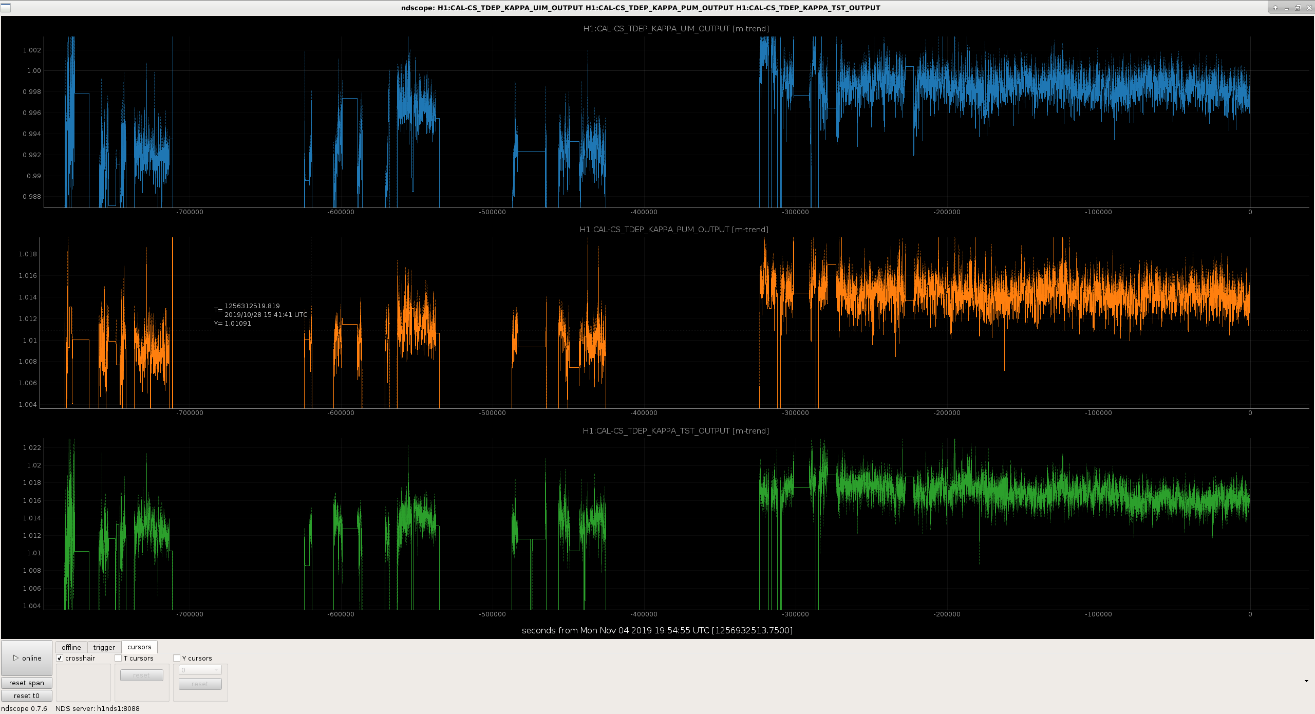
Taking a look at the work Timesh did to process the 2019-10-28 actuator data, the answers are

                           UIM                     PUM                    TST          
Reference Model         7.67e-08 (N/ct)         6.036e-10 (N/ct)     4.727e-12 (N/ct)
MCMC Fit                7.564e-08 (N/ct)        6.065e-10 (N/ct)     4.781e-12 (N/ct)
kappa via MCMC          0.986054                1.00483              1.0115
kappa via CALCS         0.995                   1.0107               1.0133

So these should be close enough that we don't need to update the actuator coefficients. 

Note that these will have similar 0.5% levels of systematic error that have been reported by the PCAL system in 52893 from having the wrong ETMX test mass mass. To be determined how we'll rectify this....
Images attached to this comment
Non-image files attached to this comment
H1 SUS
patrick.thomas@LIGO.ORG - posted 17:44, Monday 28 October 2019 - last comment - 14:53, Tuesday 29 October 2019(52749)
Alignment at NLN before and after vent
Sheila, Patrick

Attached is a list of alignment values and their differences for Sep 27 2019 20:59:42 UTC (1253653200) and Oct 28 2019 20:39:42 UTC (1256330400). Both of these times are at NLN. The values are taken from minute trend means.
Non-image files attached to this report
Comments related to this report
patrick.thomas@LIGO.ORG - 14:53, Tuesday 29 October 2019 (52774)
Script and results attached for slider values calibrated in microradians.
Non-image files attached to this comment
H1 CAL (CAL)
timesh.mistry@LIGO.ORG - posted 13:27, Monday 29 July 2019 - last comment - 03:18, Tuesday 29 October 2019(50894)
NCAL -- MEDM Screen Interface

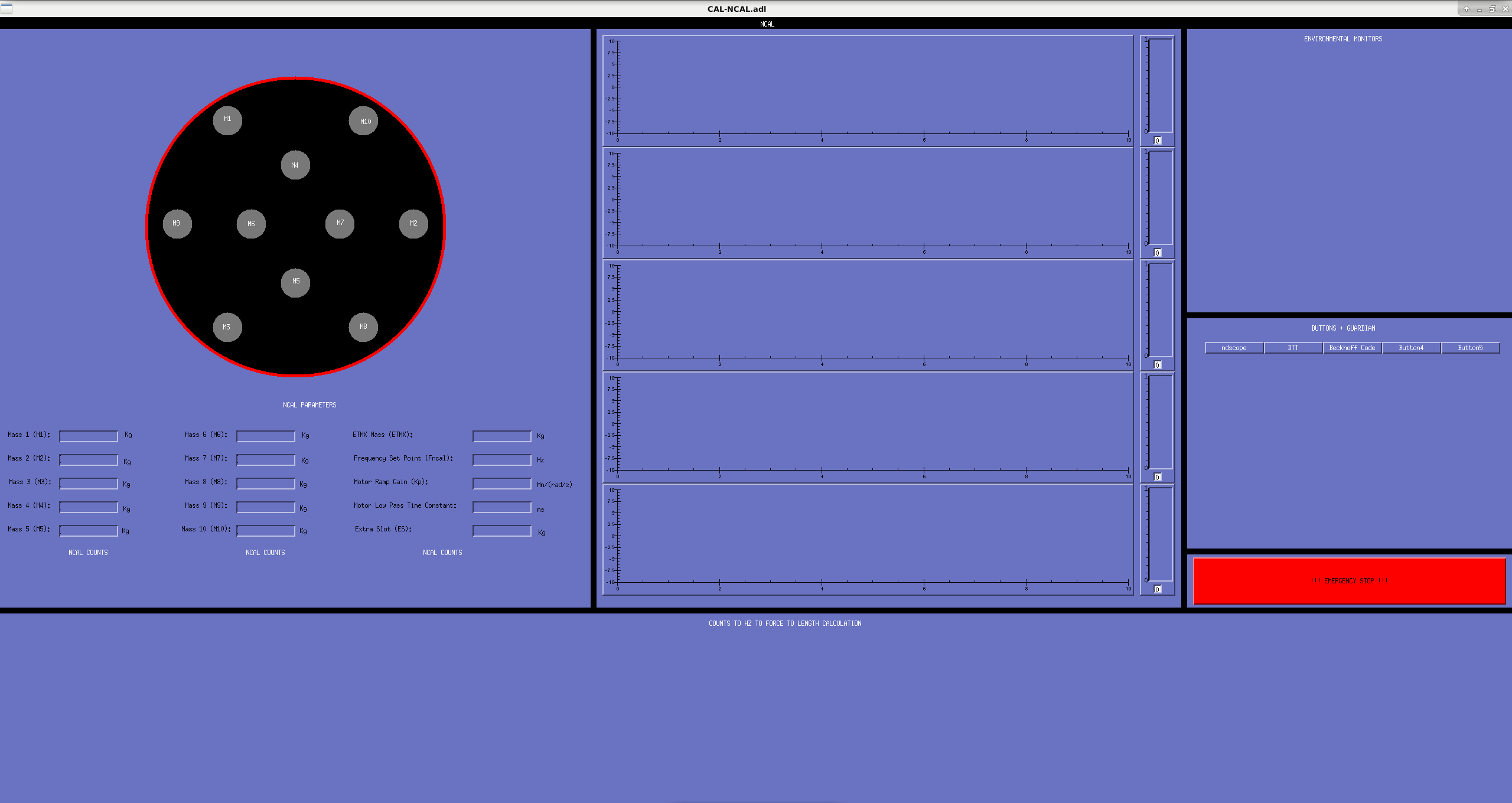
[Jeff Kissel, Timesh Mistry]

I have started drawing up an MEDM screen and a screenshot is attached to this alog. Furthermore, the screen is committed to the SVN at the following location: /opt/rtcds/userapps/release/cal/common/medm/CAL_NCAL_OVERVIEW.adl
 
Starting on the left hand side there is cartoon drawing of the NCAL with the mass positions displayed. The masses are labelled M1-M10 corresponding to the number we use for the mass allocation in the rotor. The red ring around the black disk will indicate whether the NCAL is on or off. When the NCAL is on, this red disk will be green. The NCAL masses can be entered underneath the NCAL image as well as the frequency set point, gain and low pass setting for the Beckhoff motor. There are readback positions (black boxes) for the Beckhoff counts, the NCAL frequency as a conversion from counts to frequency and the frequency as measured by analysis of the sawtooth signal.
 
I now draw your eyes to the middle section. There are 5 Cartesian plots with scale monitors to the right of them. The idea is to have a time series stream of the signal of the frequencies (see above para.), current/volts draw from the Beckhoff and any other time stream we care about (maybe accelerometers). The scale monitors will help as a visual guide for the streams of data much the way we use them for the violin monitors.
 
Proceeding right once more, there is a section that has the title 'ENVIRONMENT MONITORS'. This will hold readback for data such as temperature( XVEA, test mass etc), test mass position, etc. I'm not sure what other environment monitors we would like however, as the project evolves, this section will become more populated.
 
Lowering your gaze, you will see a section titled 'BUTTONS + GUARDIAN'. This is where there will be useful buttons for opening DTT templates, ndscope traces, viewing Beckhoff code etc. Although we are not  planning on automating anything at this stage, eventually we will want to and I think having a space ready for it is a good thing (i.e. attempting to future proof the MEDM screen).
 
Underneath this, we have the big red button. This will force stop the NCAL by turning off the power to the NCAL chassis. I put this in as a contingency however, if this is deemed as overkill then it can always be removed.
 
Last but not least, there is the section at the bottom of the screen titled 'COUNTS TO HZ TO FORCE TO LENGTH CALCULATION'.  This is were the steps to convert the NCAL signal will be computed into length in the same manor that we do for the PCAL. I have not got the front end model build yet so when that is done, this section will be filled in. This will eventually allow us to take transfer function fo the length displacement and correlate it to other signals such as PCAL calibration lines, suspension calibration lines, environmental channels and other calibration channels.
 
This screen is subject to change, most notably, for increased IOC for beckhoff and environmental monitors.
Images attached to this report
Comments related to this report
timesh.mistry@LIGO.ORG - 03:18, Tuesday 29 October 2019 (52758)CAL

I have included the MEDM screen into the main sitemap. I did this by:

a) Checked the /opt/rtcds/userapps/release/cds/h1/medm directory to make sure SITEMAP.adl is checked in and the latest version

timesh.mistry@zotws22: svn st
?       H1CDS_DAQ_LARGE_OVERVIEW_CUST.ui
?       H1CDS_DAQ_MICRO_CUST.ui
?       H1CDS_FE_MICRO_CAL_CUST.ui
?       H1CDS_FE_MICRO_CUST.ui
?       H1CDS_FE_MICRO_CUST_EDC.ui
?       H1CDS_HWWD_NODE.ui
?       H1CDS_O3_OVERVIEW_DETAIL_CUST.ui
?       H1CDS_SLOWCTRL_MICRO_CUST.ui
?       H1CDS_SLOWCTRL_SDF_ONLY_MICRO_CUST.ui
?       H1CDS_SLOW_CONTROLS_CUST.ui
?       H1CDS_WAP_MINISCULE_CUST.ui

timesh.mistry@zotws22: svn info SITEMAP.adl
Path: SITEMAP.adl
Name: SITEMAP.adl
Working Copy Root Path: /opt/rtcds/userapps/trunk/cds
URL: https://redoubt.ligo-wa.caltech.edu/svn/cds_user_apps/trunk/cds/h1/medm/SITEMAP.adl
Relative URL: ^/trunk/cds/h1/medm/SITEMAP.adl
Repository Root: https://redoubt.ligo-wa.caltech.edu/svn/cds_user_apps
Repository UUID: e3bfa956-ff0e-4416-9af7-00b7a258cde5
Revision: 20245
Node Kind: file
Schedule: normal
Last Changed Author: jeffrey.kissel@LIGO.ORG
Last Changed Rev: 20245
Last Changed Date: 2019-09-12 15:18:38 -0700 (Thu, 12 Sep 2019)
Text Last Updated: 2019-09-12 15:18:38 -0700 (Thu, 12 Sep 2019)
Checksum: ad7d77597efd5becbf2a3ac9655584594439b084

b) Modified X-Arm CAL (in the Labe/Name/Args field) to have an additional display that points to the NCAL MEDM screen that is located at:
/opt/rtcds/userapps/release/cal/common/medm/CAL_NCAL_OVERVIEW.adl
Display label is set to NCALX and Arguments is copied over from the PCALX field above it in.

c) Saved and exited the MEDM editor for sitemap. Open sitemap in execute mode and verified that the screen appears in a drop down menu X-Arm CAL as well as checked the NCALX and PCALX screen work as normal.

d) Committed the changes

timesh.mistry@zotws22: svn ci -m "Updated SITEMAP.adl to include /opt/rtcds/userapps/release/cal/common/medm/CAL_NCAL_OVERVIEW.adl for the NCALX MEDM screen as am option under X-Arm CAL. I have checked that the screen opens as normal and other screens (such as PCALX) are not affected by this change." SITEMAP.adl
Sending        SITEMAP.adl
Transmitting file data .done
Committing transaction...
Committed revision 20427.
timesh.mistry@zotws22:


Displaying reports 37861-37880 of 89075.Go to page Start 1890 1891 1892 1893 1894 1895 1896 1897 1898 End